VVG-P).
When ordering a cable, the following must be indicated sequentially: its designation with the necessary additions, the number and cross-section of the cores, the operating voltage in kilovolts separated by a dash. The letters “ozh” in brackets next to the core cross-section indicate the unambiguous design of the cable with monolithic cores, for example
Example: VVG-T 3x25(ozh) - 0.66 - VVG cable in tropical design with three monolithic cores with a cross-section of 25 mm2 for a voltage of 0.66 kV/
VVG cables can have from one to six cores with a cross-section from 1.5 mm2 to 240 mm2. The range of core cross-sections depending on their number and operating voltage of the cable is given in the table.
| Number of cores | Nominal cross-section, mm 2 | |
| cable 0.66 kV | 1 kV cable | |
| 1,2,3,4 | 1,5 — 50 | 1,5 — 240 |
| 5,6 | 1,5 — 25 | 1,5 — 25 |
Two-core VVG cables must have cores of the same cross-section. Three-, four- and five-core cables must have all conductors of the same cross-section or one conductor of a smaller cross-section (grounding or neutral conductor). Six-core VVG cables must have four cores of equal cross-section and two wires of smaller cross-section. The cross-sections of neutral conductors (in the case of a smaller cross-section than the main ones) and grounding conductors, depending on the cross-section of the main conductors up to 50 mm2, are given below.
| Main veins | 1,5 | 2,5 | 4 | 6 | 10 | 16 | 25 | 35 | 50 |
| Zero core | 1,5 | 1,5 | 2,5 | 4 | 6 | 10 | 16 | 16 | 25 |
| Grounding conductor | 1,0 | 1,5 | 2,5 | 2,5 | 4 | 6 | 10 | 16 | 16 |
The most common among VVG cables with conductors of unequal cross-sections are cables with three main and one neutral conductor (the so-called “three plus”).
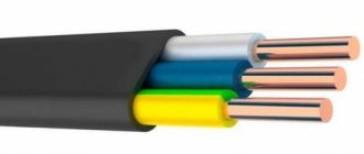
Two- and three-core VVG cables with a cross-section up to 16 mm2 inclusive can have a flat design. In round cables, the insulated cores must be twisted, and twisting with an alternating change in direction is allowed.
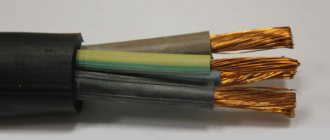
Cores with a cross section of up to 50 mm2 are round in shape. Cores up to 16 mm2 are made only monolithic; over 16 mm2 can also be twisted from individual wires (number of wires: at least 7 for sections 16, 25 and 35 mm2; at least 19 for sections 50, 70 and 95 mm2).
The insulated conductors must have a distinctive color, while the insulation of the neutral conductors should be blue, and the insulation of the ground conductors should be yellow-green. Digital marking of cores is also allowed.
To increase mechanical stability in VVG cables intended for installation in the ground, the empty space between twisted insulated conductors should be filled with bundles or a mixture of insulating materials.
The sheath must be applied in such a way that it can be easily separated from the core insulation. To do this, a Mylar tape can be laid between the core insulation and the sheath. The shell color is predominantly black.
The nominal and minimum values of the radial insulation thickness for VVG cables with a cross-section of up to 50 mm2 for an operating voltage of 0.66 kV and 1 kV are given in the table.
| Cable voltage, kV | Nominal cross-section of cores, mm | Nominal insulation thickness, mm | Minimum insulation thickness, mm |
| 0,66 | 1 — 2,5 | 0,6 | 0,44 |
| 4 and 6 | 0,7 | 0,53 | |
| 10 and 16 | 0,9 | 0,71 | |
| 25 and 35 | 1,1 | 0,89 | |
| 50 | 1,07 | ||
| 1-2,5 | 0,8 | 0,62 | 1,3 |
| 4-16 | 1,0 | 0,8 | |
| 25 and 35 | 1,2 | 0,98 | |
| 50 | 1,4 | 1,16 |
The thickness of the sheath of VVG cables depends on the twisting diameter of the insulated cores under the sheath. The nominal and minimum values of the shell thickness are given in the table.
| Diameter under the shell, mm | Nominal insulation thickness, mm | Minimum insulation thickness, mm |
| Until 6 | 1,2 | 0,92 |
| 6 – 15 | 1,5 | 1,18 |
| 15 – 20 | 1,7 | 1,35 |
| 20 – 30 | 1,9 | 1,52 |
| 30 – 40 | 2,1 | 1,69 |
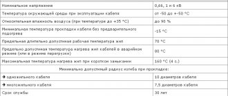
Conditions for installation and operation of the VVG power cable
Operation of VVG cable at ambient temperatures from -50°С to +50°С. Recommended for installation outdoors, in dry and damp industrial areas. The VVG cable, which has a filling between the cores, made in accordance with GOST, can be laid in the ground under conditions of low corrosive activity of the soil and the absence of significant mechanical loads. Can be laid without preheating at a temperature not lower than minus 15°C. The minimum bending radius during installation must be at least 7.5 times the outer diameter of the cable. Does not propagate combustion when laid alone. The service life of the VVG cable is 30 years.
Scope of application
Products with PVC coating are mainly used in industrial facilities and various domestic areas, since its parameters are excellent for this. The dense coating makes the VVGng power cable quite versatile when it is necessary to transmit electricity through various technical installations.
Wire in section
The VVGng LS type product with a PVC layer showed excellent performance in transmitting high power currents. Using a variety of installations, you can lay both single and multi-core wires, adhering to all GOST rules. This cable model has a high safety class, which increases its service life in various weather conditions.
You may be interested in Description of cable stocking
Note! When burning, the cable produces almost no life-threatening smoke. When manufacturing power wires, much attention is paid to the external insulation, because it protects the cores from various influences, both mechanical and natural.
Almost any power wire of the VVGng LS type is rarely used in the usual installation of an electrical network in residential premises. They are mainly used in factories, enterprises or wooden houses.
Design VVG ng ls
VVGng LS cables are mainly used in areas with increased fire safety regulations. You can lay it either alone or together with others. But for this you will need a terminal block so that the wires do not touch.
It can be laid underground (tunnels, ditches, trenches) or by air. For the latter option, it is necessary to install supports so that the cable does not sag under its own weight.
Technical characteristics of the VVG power cable
The electrical resistance of the current-carrying cable cores up to 50 mm2 at direct current should be no more than that indicated in the table.
| Nominal cross-section, mm 2 | 1,5 | 2,5 | 4 | 6 | 10 | 16 | 25 | 35 | 50 |
| Core resistance, Ohm/km | 12,1 | 7,41 | 4,61 | 3,08 | 1,83 | 1,15 | 0,727 | 0,524 | 0,387 |
The electrical resistance of the insulation per 1 km of length at a temperature of 20 0C is at least 7 - 12 MOhm, depending on the cross-section of the conductors.
Finished cables must withstand alternating voltage testing at a frequency of 50 Hz for 10 minutes. The voltage is applied between the cores and is 3 kV for cables with a rated voltage of 0.66 kV and 3.5 kV for cables with a rated voltage of 1 kV.
Cable design VVGng(A)-LS
The brand in question has the following design::
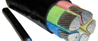
- Conducting cores (from 1 to 5) made of copper, single-wire or multi-wire. The most common section is 16mm2;
- Insulation made from smokeless PVC compositions with reduced fire hazard. Each is marked with its own color to simplify installation;
- Filling the space between the cores from a similar material. Necessary to give the cable a round shape;
- The outer shell is made of similar material.
Requirements for marking power cable VVG
On the sheath no more than every 300 mm the distinctive index of the manufacturer and the year of manufacture of the cable must be applied. For cables with a diameter under the sheath of less than 20 mm, the use of colored marking thread is allowed.
The drum cheek or label attached to the coil or drum must indicate:
— trademark of the manufacturer; — symbol of the cable (full indicating the number of cores and cross-section); — cable length in meters and number of segments; — gross or net weight when delivered in coils in kilograms; — date of manufacture (year, month); — drum or coil number.
The label must bear a technical control stamp and a certification mark.
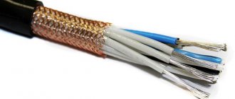
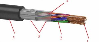
Cable shield
A special type of cable is shielded VVGE, used for transmitting audio and digital signals. Due to the fact that audio and digital signals travel through the cable, it is necessary to ensure that no distortion occurs. This requires a screen adaptation. To make a shielded wire, it is covered with a screen, that is, protection.
Screen types
- Screen made of copper or aluminum foil. It covers the cable around. But this method is fragile, so it is laid in stationary conditions.
- Shielded mesh shell. These products are highly reliable, but do not provide 100% coverage of the signal wire. Manufacturers can increase the density of shielded wire, but the cost will increase.
- Spiral braided wire. The cable is flexible and stronger than foil, but the coating does not achieve great results.
Weight depends on screen type.
Judging by the emerging shortcomings of each type of screen, a double shielded cable has appeared. This may be a combination of mesh and foil or two layers of spiral braids. Drain wire is added to strengthen the shielded cable.
An important technical characteristic of a shielded cable is the thickness of the foil. Manufacturers are constantly optimizing the manufacturing process, increasing the value to 100 microns. VVGng-LS manufacturers have taken care of a wide variety of cables that transmit electric current. They have different sections, lengths, and functionality.
Weight and dimensions parameters of the VVG power cable
The approximate external dimensions and weights of individual cables with a cross-section of up to 50 mm2 for packaging and transportation purposes are given in the table. The given values may differ for cables of different batches and manufacturers by 10% less or more.
| Cable cross-section | External size value for packaging and transportation purposes, mm | Weight value for packaging and transportation purposes, kg/km |
| Flat cables | (a x b) | |
| 2x1.5 | 5 x 7.5 | 70 |
| 2x2.5 | 5.5 x 8 | 90 |
| 2x4 | 6 x 9.5 | 140 |
| 2x6 | 7 x 10.5 | 180 |
| 3x1.5 | 5 x 9.5 | 95 |
| 3x2.5 | 5.5 x 11 | 135 |
| 3x4 | 6 x 13 | 200 |
| Stranded cables | Diameter | |
| 3x1.5 | 8 | 90 |
| 3x2.5 | 9,5 | 135 |
| 3x4 | 11 | 200 |
| 3x6 | 12 | 260 |
| 3x10 | 14,5 | 410 |
| 3x16 | 17 | 590 |
| 3x25 | 20,5 | 810 |
| 3x35 | 23 | 1300 |
| 3x50 | 27 | 1700 |
| 3x4+1x2.5 | 12 | 230 |
| 3x6+1x4 | 14 | 310 |
| 3x10+1x6 | 16 | 480 |
| 3x16+1x10 | 19 | 650 |
| 4x1.5 | 8,5 | 110 |
| 4x2.5 | 10 | 170 |
| 4x4 | 12 | 240 |
| 4x6 | 13 | 320 |
| 4x10 | 16 | 510 |
| 4x16 | 19 | 750 |
| 4x25 | 23 | 1150 |
| 4x35 | 26 | 1550 |
| 4x50 | 31 | 2200 |
| 5x1.5 | 9,5 | 135 |
| 5x2.5 | 11 | 205 |
| 5x4 | 13 | 300 |
| 5x6 | 14 | 405 |
| 5x10 | 17,5 | 630 |
| 5x16 | 21 | 950 |
| 5x25 | 26 | 1450 |
| 5x35 | 29 | 1900 |
| 5x50 | 35 | 2700 |
Cable core thickness - cross-sectional diameter calculation
The actual thickness of the cable cores is a key indicator that every electrical engineer and electrical installer needs to know. The fact is that the actual diameter of the electrical conductor may differ from that declared by the manufacturer and given in the technical documentation for the cable and wire product.
If the magnitude of the deviation is within the tolerances allowed by regulatory documents (read about this in the material below), then there is no problem. What can be the result of using an electrical cable with a much, for example, 20-30% smaller cross-section than indicated on its marking? Carrying out calculations of power line power according to factory documents and laying an actually thinner cable with a high degree of probability will cause overheating of the electrical conductors, melting of the insulation and sheath. Possible consequences - disruption of uninterrupted power supply, smoke, fire
healthy:
We recommend reading our article Undersized cable cross-section - check by calculating resistance in accordance with GOST.
Tolerances for section deviations
Regulatory documentation does not directly regulate this group of indicators. However, GOST 22483-77 and its updated versions contain requirements for acceptable parameters of electrical resistance of conductors depending on their cross-section. Using simple formulas, it is easy to carry out the necessary calculations. For example, let’s select the minimum cross-section for an aluminum core of 3 mm2.
According to the formula R0=p*(l/S), where:
- R0 - design resistance,
- p - specific (0.0271*10-6 Ohm*m),
- l - 1000m,
- S—section in m2.
We get an electrical resistance value of 9.03 Ohm*km. According to GOST, the value should not exceed 10.1 Ohm*km. We calculate the calculated value of S from the formula in reverse, using the indicator 10.1. S=2.68 mm2 means that for a 3 mm2 core the maximum tolerance for cross-section deviation is 89.3% (2.68/3).
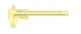
Calculation of diameter by section
If the cable product is not marked, then the cross-section of the electrical conductor can be determined by the diameter of the core.
Measurements are carried out using simple available tools, and calculations are made using the formula. To find out parameter D, we measure the “bare” conductor:
- micrometer or caliper;
- with an ordinary ruler (for example, 20 turns are wound tightly around the handle, the total length is measured, which is divided by 20).
For example, the diameter of the conductor is 3.5 mm, then the cross section is S = 0.785 * 3.52 = 9.6 mm2. Round to the nearest standard value and get 10 mm2.
To calculate the cross-section of a multi-wire core, the obtained value for 1 wire should be multiplied by their number.
VVG power cable load currents
Permissible load currents for cables with a cross-section of up to 50 mm2 laid in air are indicated in the table.
| Nominal cross-section of cores, mm2 | Permissible load current, A | ||
| With two main cores | With three main cores | With four main cores | |
| 1,5 | 24 | 21 | 19 |
| 2,5 | 33 | 28 | 26 |
| 4 | 44 | 37 | 34 |
| 6 | 56 | 49 | 45 |
| 10 | 76 | 66 | 61 |
| 16 | 101 | 87 | 81 |
| 25 | 134 | 115 | 107 |
| 35 | 166 | 141 | 131 |
| 50 | 208 | 177 | 165 |
Cable insulation and sheath thickness
The thickness of the cable insulating cover depends on the design features of the product, its rated electrical voltage and the cross-section of the electrical conductors.
The thickness of the insulating layer made of plastic polymers (PVC and polyethylene) and rubber is regulated by GOST 23386-78. This document establishes 6 categories (the index “p” is added to them - plastic - rubber):
- I-1 - for cable products in a sheath that operate in power systems of 0.22/0.38 kV with an alternating voltage rating of up to 0.22 kV or constant voltage - up to 0.7 kV (thickness range IP-1 for sections 0.35 -95 mm2 - 0.4-1.2 mm; Ir-1 - 0.6-1.6 mm);
- I-2 - without shell, 0.22/0.38 kV, up to 0.22 or 0.7 kV (IP-2 for 0.35-95 mm2 - 0.5-1.6 mm; Ir-2 - similar to Ir-1);
- I-3 - in a shell, 0.22/0.38 kV, up to 0.22 or 0.7 kV, 0.4/0.6 kV, up to 0.4 or 1 kV (IP-3 for 0.35 -500 mm2 - 0.5-3.0 mm; Ir-3 for 0.5-500 mm2 - 0.8-3.0 mm)
- I-4 - without shell, 0.22/0.38 kV, up to 0.22 or 0.7 kV, 0.4/0.6 kV, up to 0.4 or 1 kV (IP-4 for 0.35 -500 mm2 - 0.6-3.0 mm; Ir-4 - similar to Ir-3);
- I-5 - 0.4/0.6 kV, up to 0.4 or 1 kV, 1.8/3 kV, up to 1.8 or 6 kV (IP-5 for 4-500 mm2 - 2.2-3 .0 mm; Ir-5 for 1.5-500 mm2 - 1.8-3.8 mm);
- I-6 - 3.6/6 kV, up to 3.6 kV (IP-6 for 10-500 mm2 - 3.0-3.2 mm; Ir-6 for 10-150 mm2 - 4.0 mm).
The insulation thickness of cables up to 10 kV from impregnated special paper is established by GOST 23436-83 and is 0.6-2.75 mm.
The thickness of the cable sheath depends on factors similar to those for the insulating layer; their standards and categories are determined by GOST 23386-78 (the indices “p” and “p” are also used in the designations):
- Ob-1 - portable cables used in difficult conditions (heavy equipment for digging earth, etc.). For diameters of products under the shell of 6-60 mm, the rating Obp-1 is 1.2-4.0 mm, Obr-1 - 1.5-6.0 mm;
- Ob-2 - stationary electrical cables and mobile for average conditions (all cases that are not included in Ob-1 and Ob-3). Ranges Obr-2 - 1.2-3.0 mm, Obr-2 - 1.5-4.5 mm;
- Ob-3 - portable cable products that operate in the absence of mechanical influences, incl. household For 6-15 mm Obr-3 - 1.0-1.2 mm, Obr-3 - 0.8-1.2 mm.
According to GOST 23386-78, the maximum discrepancy in the thickness of the cable insulating cover can reach minus 10%, the protective sheath - minus 15% for polymer materials, minus 20% for rubber and vulcanized PE.
In cases that are technically justified and agreed upon with the buyer or consumer, the thickness of the insulating layer and sheaths can be reduced or increased, which is necessarily reflected in the technical documents for cable products.
The casings of cable and wire products are also made from other materials, for example:
- lead - the thickness of the lead sheath is usually 0.95-2.8 mm (1.1-3 mm in communication cables) and depends on the cable diameter inside the sheath;
- aluminum - the nominal thickness of extruded shells varies from 1.1 to 2 mm with a maximum negative deviation of 0.2-0.3 mm, welded ones - 0.95-1.1 mm (0.05 mm);
- steel - the shell is a “roll” of tapes with a thickness of 0.3-0.5 mm;
- polyamides or nylon - up to 0.15 mm.
Available methods for quality control of VVG power cable
Control methods are presented that, while not strictly complying with GOST, allow preliminary conclusions to be drawn about the quality of the cable if the measured values differ significantly from the regulated ones. The final conclusion about the cable's compliance with GOST can be made only after testing the cable in a specialized laboratory using strict methods and in the volumes specified in the standard.
Visual inspection The following can be checked: the number and color of cores, the number of wires in the core, the integrity of the insulation and sheath and the ease (without damage) of their separation.
Measuring structural dimensions Can be checked using suitable measuring instruments: insulation and sheath thickness. Measuring the diameter of the wires dpr and calculating the cross-section of the core using the formula 0.785dpr2N (where N is the number of wires in the core) is not a strict method for controlling the cross-section of the cores, because confirmation of cross-section compliance is electrical resistance, however, a significant deviation of the calculated cross-section from the nominal (more than 10%) may serve as a basis for doubts about the quality.
Measuring the electrical resistance of current-carrying conductors. It can be carried out on a finished cable with an ohmmeter with a suitable measurement limit (for cables with a small cross-section at a normal length in a coil or on a drum it can be several Ohms) and recalculated to a length of 1 km. If the cable has twisted cores, the obtained values should be reduced by 1.02 times. Particular attention should be paid to making good contact with the test leads.
Winding test after exposure at low temperatures If you have a large freezer compartment of a household refrigerator with temperatures down to minus 150C, you can check the quality of the cable sheath with an outer diameter of up to 20 mm. To do this, a piece of cable approximately 1.2 m long, rolled for compactness into a ring with a diameter of at least 40 cm, is placed in the freezer for 45 minutes, after which it is removed from the chamber and, in no more than 5 minutes, is wound onto the cylinder (drum) in a full turn first in one direction, then in the opposite direction. The material of the cylinder (drum) can be any - wood, plastic, metal. The diameter of the cylinder (drum) should be 15(Dн + d) ±5%, where Dн is the outer diameter of the cable in mm (for flat sheath thickness), d is the diameter of any of the main insulated cores in mm. A high-quality shell should not have cracks or tears.
Decoding the abbreviation
- the letter A at the beginning of the abbreviation means that the core material is aluminum; if the letter A is absent in the name of the cable, then the core is made of copper;
- the first letter B indicates the material used for internal insulation; this letter codes polyvinyl chloride;
- the second B denotes the material from which the outer shell is made, it indicates polyvinyl chloride;
- the letter G indicates the absence of a protective coating (G - bare);
- the letters ng indicate that the wire is flame retardant;
- the English letters ls (low smoke) indicate that the wire has low smoke emission;
- the letter P means that the cable has an inner sheath made of thermoplastic polyethylene;
- the letters BB indicate the presence of an armored coating made of steel tape;
- the letters Шв give information about the outer layer of the polyvinyl chloride hose.