Thyristor converters make it possible to supply electric current pulses of various configurations to the motor. Features and throughput vary depending on system specifications and the device itself.
Recently, industrial systems driven by electricity increasingly include a thyristor converter for the DC motor. These semiconductor valves allow the drive to be controlled over a significant range: the current can exceed hundreds of amperes, and the voltage reaches 1000V and higher.
Despite its increased technical performance, the thyristor electric drive is distinguished by its compact overall dimensions. At the same time, its performance exceeds that of other systems for similar purposes, and the operating temperature range allows the DC motor to be operated in an environment from -60 to +60 Celsius.
What is a thyristor
A thyristor system is a partially controlled voltage conversion system. The general operating scheme involves activation of the drive at the moment the potential of the required level is applied to the control electrode. To turn off the thyristor DC motor converter, it is necessary to perform a forced circuit break. This can be done in three ways:
- apply a quenching voltage having a value opposite to the starting pulse;
- turn off the power supply to the entire drive;
- pass the supply current through zero.
The rotation speed of the electric motor depends on the average voltage value that has already passed through the rectifier. A thyristor electric drive allows you to control the moment at which the main flow of rectified voltage is supplied and its delay. By adjusting the feed torque, the overall control of a DC motor can be achieved.
Development
The electrical circuit of a thyristor converter-motor (for example, KHP) for smooth switching can be of two types:
- Single-phase;
- Multiphase.
Depending on the type of design, the ratios of calculation units and the operating principles of the converter vary.
Photo - zero circuit of three-phase conversion
This drawing schematically shows the change in electrical energy when the thyristor converter operates in rectifier and inverter mode. At the same time, for a bridge circuit you can make the same diagram, but only consisting of two zeros. It is this type that is most often used when designing converters for machine tools. This is due to the fact that the initial phase voltage in it is twice the phase voltage (Udo) in the zero operating circuit.
Photo - food
A single-phase circuit is used to control the power supply and drive operation of machines with high inductive reactance. It operates within a power range from 10 kW to 20, much less often at higher powers. For example, suitable for an electric oven or home machine.
Photo - single line diagram
Three-phase is used for equipment where 20 kW or more is required for operation. For example, for synchronous drives, crane and excavator engines. Another popular multiphase control circuit is six-phase (Camron). Her project involves the use of a surge reactor in the design, which is aimed at controlling low voltage and high current. This power electrical device transmits and converts electrical energy in parallel rather than serial (like most similar devices). It is more difficult to develop with your own hands, but the degree of reliability and efficiency is much greater than that of a single-phase thyristor converter. But such a reversible controller has a serious drawback - its efficiency is less than 70%.
You can make your own converter with your own hands, but a lot depends on the base used. Below is a diagram developed on the basis of Micro-Cap 9. The main feature of this model is the need for joint modeling of various nodes.
Photo - Thyristor equalizer circuit
Video: how thyristor converters work
General classification
By conducting a study of a system that assumes the presence of a thyristor, you can determine the most optimal switching circuit. The selected startup type directly determines the average voltage level produced by the rectifier in the absence of operator intervention. In cases where a thyristor is used for a DC motor, two classes of thyristor converters are used - bridge and equipped with a zero-value output.
A bridge-type thyristor converter is usually installed in high-power systems. This is optimal due to the fact that each such thyristor can have a lower voltage level, which makes it possible to distribute the total load between several nodes and reduce the load on each of them. In addition, the voltage rectified through the bridge thyristor will not have a constant component, which increases the stability of operation when electric current passes through the converting windings.
Another difference between different classes of thyristors is the number of phase outputs. Equipment and devices with low power consumption require a thyristor to have only a few phases. If the converter is designed to operate in highly loaded systems, its design may include from 12 to 24 phase contacts.
Regardless of the chosen activation type and overall design, this category of voltage converters will have all the advantages of using thyristors. This includes the complete absence of rotating parts, which accelerate the wear process and require periodic replacement. This leads to another advantage – low inertia. The main difference from simple electromechanical electric current converters is their compactness, which has a positive effect on compatibility with devices where there is little free space.
With all its advantages, the thyristor converter has a number of disadvantages:
- if the voltage is adjusted downward, the output power begins to fall in proportion to the decrease in power supply;
- when the converter operates, higher harmonics are created, which immediately enter the power supply network of the entire system;
- The thyristor is rigidly connected to the power supply circuit, which is why the slightest voltage surge is immediately reflected in the system. Changing the characteristics of the current supplied to the motor creates a push on the axis, abruptly changing the speed of its rotation, and this in turn causes a surge in current.
The performance of an electric motor, which operates in conjunction with a thyristor converter, directly depends on the voltage level supplied to the armature. The load generated by the drive also plays an important role.
Operating principle and design features
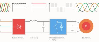
To convert the load, a thyristor high-voltage circuit converter based on IGBT is used. A thyristor-based frequency converter is a device for converting current, adjusting its parameters and current level. Using a frequency converter, you can equalize the values of drive parameters on electric motors: angle, shaft speed at startup, and others.
Thyristor equalizer circuit.
For a DC motor, a thyristor converter is used. The advantages of this device have allowed it to be widely used. Benefits include:
- Efficiency (95%) for the PN-500 brand.
- Control area: motors from low power to megawatt.
- Can withstand significant impulses of engine starting loads.
- Durable and reliable operation.
- Accuracy.
This system also has disadvantages. Power is at its lowest level. This is evident in the precise regulation of the production process. Additional devices are used as compensation. Such a frequency converter cannot operate without interference. This can be seen during the operation of sensitive electrical equipment and radio devices.
Components:
- Reactor in the form of a transformer.
- Current rectification blocks.
- Reactor for smoothing the transformation.
- Overvoltage does not affect the protection.
Converters (2017) are connected through a reactor. The transformer serves to match the output and input voltage sections and equalize the voltage between them. The electrical connection circuit includes a smoothing reactor. The frequency converter has a circuit that contains a smoothing reactor.
The frequency converter passes the load. The load goes to the rectifier blocks in the output link. To equalize the power supply of several devices, induction consumers are connected on special buses.
There are two types of frequency converters - high-frequency and low-frequency. The selection of the desired model is carried out according to the necessary parameters of the electrical circuits. In 3-phase machines, the connection type is different. 1-phase current tolerates impacts, but efficiency is lost when converting to 3-phase current.
The system is used in smelting production, control of lifting and transport devices, and welding production. This principle of load operation is implemented by an engine-generator system. At the lowest engine speeds, the spindle speed is adjusted over a wide range and different characteristics of the motor drive are adjusted.
Typical design and operating principle
A thyristor is a semiconductor made of silicon. Typically, it consists of four conductive layers. The assembly is carried out on a copper base, which has six sides and a threaded shank. This element is complemented by a main structure, in the production of which special silicon is used.
The four-layer transmission complex has two outputs - control and negative. From the outside, the entire structure is protected by an iron casing shaped like a cylinder and equipped with an insulating layer. Using a thread, the thyristor is installed in a special mounting location and connected to the positive pole of the power circuit with anode voltage.
Homemade frequency converter using thyristors
I took an asynchronous motor with a power of 2 kW. I assembled everything myself. It was necessary to obtain three phases from a 220 volt network to control the electric motor. It was necessary to control the engine speed and not receive output voltage surges.
After looking at information on the Internet, I found various types of diagrams. There are many different options available. I settled on this particular circuit, since its power is up to 4 kW, and the protection functions work fine.
I took the case from the computer system unit and installed all the parts into it. I could have saved money and done it differently, but I already had this closet. I bought the power supply separately.
Although it was possible to assemble the power supply circuit yourself. I didn’t consult anyone and started collecting myself. I assembled a set of capacitors with a relay, a diode bridge with field-effect transistors. I installed a cooling fan in case there is a 4 kW load motor and it gets hot. With motors of 2-3 kW, the converter works normally, there are no problems with heating. I decided to make sure that the fan did not work constantly, since it would suck dust into the cabinet, and then it would need to be cleaned. I decided to make the cooler turn on and off at certain temperatures.
To do this, I made a small adjustment board with a relay, although you can also buy one. In half a day I assembled this board from available parts. There is a shunt in the cabinet that is configured for a 4kW motor. If there is an overcurrent, the motor will turn off. The converter board is made on a microcontroller. If you change the controller and install a quartz at 20 MHz and two capacitors in the quartz harness, then you can change the firmware, place a monitor and a speed control knob on the housing panel. During operation, you can change the frequency.
But I didn’t do this because I needed extra money. This frequency generator cost me about three thousand rubles, this is for 2017. A factory converter based on thyristors of the same class, even if in a smaller housing, would cost about 7-10 thousand rubles. It depends on the manufacturer's brand.
Such a frequency converter can be used on CNC machines on a spindle, and control can be transferred to the control panel. Let's check how it works. We turn on the start, the engine turns on smoothly and runs. Turn it off, then turn it on in reverse and repeat the operations. Everything is working fine.
I recently bought a straightener for 1000 rubles. This is inexpensive for a thyristor rectifier. Such diodes have to be ordered from other regions. If the control electrode is shorted to the anode, it turns into a diode. If we remove it, it turns into a thyristor. If you solder a control board to the wires, you can control it. The result is a thyristor rectifier. I put it on the welding machine. You should not use a thyristor rectifier for manual arc welding, since when welding there is a large pulsation, the welding seam is of poor quality. For a semi-automatic machine, thyristors are suitable; pulsations are not important there.
Work management
The general scheme of operation is the passage of electricity through the thyristor under the action of anode voltage. In this case, the magnitude of the output voltage depends on the control current, which is supplied to the control electrode. If the supply of control current is interrupted, the anode voltage going to the consumer will begin to increase, while maintaining a low value.
As the incoming voltage increases, the amount of current required to turn on the thyristor decreases. There is a direct proportion between these indicators, which can be traced in any design of a thyristor converter.
Using the sine law to control the incoming voltage also allows you to reduce the voltage level. In this case, the control current decreases in proportion to the pulse required to open the main mechanism. Maintaining a constant control voltage does not lead to the opening of the thyristor when its level is lower than that of the control pulse.
Increasing the control voltage causes the thyristor to open under certain conditions. To do this, it is necessary to ensure that the control pulse indicator is exceeded. Using the ability to configure the characteristics of the control pulse, you can change the opening angle of the thyristor in the range from zero to 90 degrees.
In cases where it is necessary to open the thyristor to a larger angle, the control voltage changes to alternating. In most situations, the amplitude of the current is sinusoidal. When the voltage reaches a value equal to the point at which the sinusoid intersects the value of the control pulse, the thyristor opens.
By changing the sine wave interval to a smaller or larger direction, you can also adjust the opening angle of the converter transmission mechanism. This type of thyristor operation control is called horizontal and is implemented through the use of a device called a phase shifter. The opposite type of control - vertical - involves shifting the sinusoid up or down, which also leads to a change in the opening angle of the conductor. To determine the final value required to influence the angle, it is necessary to calculate the sum of the alternating control voltage and the direct current that forms the sine wave. It is possible to set the specific angle at which the thyristor must be opened by adjusting the constant voltage.
Once the thyristor is open to the desired angle, the system maintains the specified position until the positive half-cycle is completed. During this period of time, the control voltage does not affect the functions of the conductor. Thanks to this feature, the use of pulse control becomes possible.
Pulse control consists of applying periodic wave influences equal in magnitude to the control voltage and having a positive indicator. To normalize work, impulses should be released at clearly defined points in time. This type of control allows you to improve the clarity of the functioning of the system, which includes a thyristor converter.
By changing the opening angle of the thyristor, you can adjust the shape of the pulses transmitted to the consumer device. It is worth considering that such control leads to a change in the weighted average voltage level at the terminals of the energy-consuming device or mechanism.
Using a transformer
Sometimes, to ensure more accurate and stable control of the operation of thyristor converters, third-party components, for example, transformers, are used. In this case, the primary winding of the latter will be powered directly from the supply AC network. In this case, the secondary winding will include a full-wave rectifier, which has an increased level of inductance in a circuit where a constant voltage is present.
With this approach, it becomes possible to eliminate the ripple effect of the current released from the rectifier. However, only full-wave rectifiers adapted for alternating voltage have this property. The amplitude of the rectified current must also meet certain characteristics: in this case, its shape must be sawtooth or rectangular. Therefore, the rectifier also performs the function of converting the AC voltage waveform.
During operation, the transformer capacitors alternately receive two forms of electric current at once. A rectangular amplitude of energy supply is observed in charging flows. The plates, in turn, accumulate a sawtooth electric current, which is subsequently applied to the transistor bases. If this type of voltage is present, it is classified as a reference voltage.
Each transistor installed in the transformer is equipped with its own base, which has a dedicated circuit. It operates with a constant voltage, which leads to the appearance of positive potentials on all transistor bases, provided that the sawtooth current on the capacitor plates is zero. In this case, the transistors are opened at the moment of formation on the basis of a negative potential.
In order for the above process to start, it is necessary to increase the negative value of the reference current so much that it exceeds the value of the control voltage. This is done depending on the current level of the latter for a certain phase angle. In this case, the opening time of the transistor will directly depend on the value of the control voltage.
If one or both transistors are open, the second or third primary windings of the transformer installation pass a rectangular pulse through themselves. At the moment the leading edge passes, the secondary winding generates a volume of electric current that is released directly onto the thyristor electrode, which controls its opening.
When the voltage wave passes and the primary winding is touched by the trailing edge of the pulse, the same current is generated in the secondary winding, but of reverse polarity. This voltage is then shorted to a semiconductor diode, which continuously shunts the secondary winding of the transformer. In this case, the thyristor converter is inactive because it does not receive power.
If it is necessary to implement a parallel connection of a thyristor array to two transformers, the circuit configuration changes. To do this, two pulses with opposite phases are generated, the shift of which is 180 degrees.
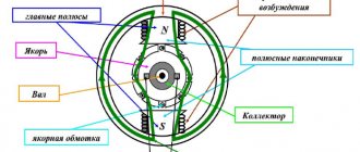
6.2. Electric drives using the thyristor converter-DC motor system
The torque developed by the motor is proportional to the armature current and field flow
. (6.3)
From equations (6.1) and (6.2) it is easy to obtain the dependence of speed on armature current, which is called the electromechanical characteristic of the motor
. (6.4)
Substituting the values of the armature current from (6.3) into (6.4), we obtain the equation for the mechanical characteristics of the motor
. (6.5)
If the engine operates in all modes with a constant excitation flux, then the kF
considered constant
. (6.6)
Then equations (6.2), (6.4) and (6.5) will look like:
(6.7)
(6.8)
(6.9)
Strictly speaking, when the load on the shaft changes, when the armature current changes, the motor flux due to the demagnetizing effect of the armature reaction does not remain constant. To eliminate the influence of the current in the armature circuit on the excitation flux on large machines, a compensation winding is used, which is connected in series with the armature winding and is located at the poles of the machine, enhancing the excitation flux. However, even for uncompensated machines, in engineering calculations the demagnetizing effect of the armature reaction is usually neglected, entrusting the ensuring of the linearity of the mechanical characteristics of the motor to closed control systems. In motors excited by permanent magnets, the armature reaction is practically not observed. For a more accurate account of the influence of the armature reaction on the mechanical characteristics, we recommend that you refer to [1-3].
The natural mechanical characteristic of an independently excited DC motor is shown in Fig. 6.2.
Stiffness of natural mechanical characteristic β
for the engines under consideration is usually high and equal to
. (6.10)
Note that in equations (6.4), (6.5), (6.8), (6.9) the terms and are equal to the engine idle speed ω 0
. Taking (6.10) into account, we obtain a convenient expression for the mechanical characteristics at a constant excitation flux
. (6.11)
The speed of an independent excitation DC motor can be controlled in three ways:
- By introducing additional resistance into the armature circuit.
- By changing the voltage supplying the armature circuit of the motor, with a constant excitation flow.
- By changing the excitation current, i.e. changing the magnetic flux of the motor.
When introducing additional resistance into the armature circuit, no-load speed ω 0
remains unchanged, but the slope of the mechanical characteristics changes, i.e. their rigidity decreases (see Fig. 6.3). This method of speed control is not currently used, since the introduction of additional resistance is associated with energy losses in this resistance.
The main way to regulate the speed of independently excited DC motors is to regulate the voltage supplied to the motor armature.
In this case, the speed change is made downward from the main (nominal) speed, determined by the natural characteristic (Fig. 6.4). Increasing the supply voltage above the rated one, as a rule, is not recommended, because this may degrade commutation at the collector.
As the armature voltage decreases, the no-load speed ω 0
, and the rigidity of the mechanical characteristics remains constant. Smooth control, the absence of additional energy losses during control and high rigidity of mechanical characteristics constitute the main advantages of this method of speed control.
Regulation of speed above the main one is carried out by reducing the excitation current (flow) (see Fig. 6.5). With a decrease in magnetic flux F
according to (6.5), the idle speed
ω 0
and at the same time the rigidity of the mechanical characteristics of the engine decreases (see Fig. 6.5a).
Increasing the excitation current above the rated one is impractical, since due to the saturation of the magnetic circuit of the machine, a significant increase in the magnetic flux will not occur, and the thermal conditions of the motor will be disrupted. The electromechanical characteristics of the motor when the field is weakened will have the form shown in Fig. 6.5b. These characteristics, as follows from (6.4), on the abscissa axis converge at one point corresponding to the short circuit current. Note that the scale along the x-axis in Fig. 6.5a and 6.5b is different.
When analyzing the mechanical characteristics during field weakening, it should be borne in mind that when operating with a constant static torque, the armature current increases as the flux weakens. So, if the static torque on the motor shaft is equal to the rated one, then at the rated armature voltage U yan
the engine will operate in stage 1 (see Fig. 6.5a). If, for example, the excitation flow is weakened by 2 times, then the idle speed of the engine ω02 increases by 2 times. If the engine torque remains constant and equal to the rated one, then the engine will operate in point 4. However, as follows from (6.3), the armature current will increase by 2 times. Therefore, prolonged operation of the engine in stage 4 is unacceptable. From this example it follows that, simultaneously with increasing speed, it is necessary to reduce the long-term permissible (nominal) torque under heating conditions. The rated torque line for field weakening is shown by the 1-2-3 curve. Similarly, when the field is weakened, the permissible maximum torque, determined by the commutation conditions on the collector, decreases. Since when the field is weakened, the speed increases approximately in proportion to the degree of field weakening, and the long-term permissible torque decreases in proportion to the ratio, the engine power remains approximately constant. Therefore, regulation by field weakening is called regulation with constant power, in contrast to regulation by changing the armature voltage with a constant excitation flux, which is called regulation with constant torque.
For electric drives of many mechanisms, combined control is used, the so-called two-zone speed control. Mechanical characteristics for this control method are shown in Fig. 6.6. In the first zone, the engine speed is in the range from zero to the main speed ω 0н
regulated by changing the armature voltage at a constant excitation flow
F n
. In the second zone, regulation is carried out by changing the excitation current (flux) at a constant rated armature voltage. Accordingly, the nominal torque in the first control zone remains constant, and in the second zone it decreases in proportion to the decrease in flow. The maximum permissible motor speed during field weakening is determined by the mechanical strength of the armature and the switching conditions on the commutator. This speed is indicated in the engine catalogue.
Field weakening is also used in single-zone speed control to set the main (maximum) speed. Unlike synchronous and asynchronous motors, DC motors do not have a strictly defined rated speed. The catalogs indicate the nominal and maximum speeds. For example, if a 100kW motor is specified to have a rated speed of 1000rpm and a maximum speed of 2000rpm, then the base speed can be set within these limits by selecting the appropriate field current value. For example, - 1600 rpm; in this case, the engine power will remain equal to 100 kW. This is convenient when designing the kinematic diagram of a working machine.
For highly dynamic electric drives of low power (up to 20 kW), the use of high-torque DC motors with permanent magnet excitation is effective. Thanks to the use of high-energy permanent magnets based on rare earth elements (for example, samarium-cobalt alloy), these motors are capable of developing high torque, especially at low rotation speeds (when the current switching conditions on the collector are easier). The ratio of the starting torque of such a motor to the nominal one is 10-12, while for motors with electromagnetic excitation this ratio does not exceed 2-4. Such motors are used in metal-cutting machines with numerical control, in robot drives and servo electric drives for various purposes [1-9].
In some cases, independently excited motors are equipped with a “light” series excitation winding, which creates an M.F.S. at a rated armature current of about 20% of m.m.f. independent excitation windings. Such mixed-excitation motors are used in cases of multi-motor drive, when two or more motors operate on one shaft or their shafts are connected mechanically (for example, by a conveyor belt). In this case, the speed of all motors will be the same, but due to the non-identical characteristics of the motor, the problem of uniform distributing the load between them. Due to the presence of a series field winding in a more loaded motor, the flux increases and the armature back-emf increases, which leads to a decrease in the armature current. On the contrary, a less loaded engine will have a slightly lower flux, its e.m.f. will be lower and the armature current increases accordingly. Thus, due to the presence of a weak series winding, the armature current is equalized between motors powered by a common voltage source.
Independently excited DC electric motors can operate in three braking modes: regenerative braking, dynamic braking and back-on braking.
The regenerative generator braking mode is reflected in the mechanical characteristics in the second quadrant when the engine speed exceeds the idle speed ω>ω 0
(Fig. 6.7).
In this case, the e.m.f. armature E I
exceeds the supply voltage of the armature circuit
E I > U I
and the current in the armature circuit will flow under the action of the emf.
anchors E i
; the sign of the current will be opposite to the sign of the supply voltage, which means that the braking energy is transferred to the DC power supply network. This implies three conditions for the existence of the regenerative braking mode.
- C
Fig.6.7. Mechanical characteristics of a DC motor in regenerative braking mode
The power supply must allow current to flow counter to the voltage of the power source; this condition is especially important in the case of powering a DC motor from semiconductor converters, the elements of which have one-way conductivity of current (see §6.2).
- The power source must be able to receive the energy given by the engine and transmit it to the power supply network; Thus, regenerative braking mode is not possible if the drive is powered by an autonomous diesel generator set.
- In order for regenerative braking to be possible within a given speed control range, the control must use a method of varying the voltage supplied to the motor's armature circuit.
In the regenerative braking mode, equations (6.1) and (6.5) take the form:
The main advantages of regenerative braking are: energy efficiency associated with the beneficial use of braking energy, high rigidity of mechanical characteristics, smooth transition from driving to braking mode on the same characteristic. Due to this nature of the mechanical characteristics, the quality of drive control is improved. Let's return to considering Fig. 6.7. Let the engine operate in point 1 in motor mode with a static torque M s
.
If the operator wants to reduce the speed, he reduces the voltage of the power source from U i
1 to
U i
2. At the first moment, the motor speed cannot change due to mechanical inertia, and the engine switches to operation in point 2.
In this case, a braking torque appears on the motor shaft equal to the sum of the motor braking torque and the static torque. The engine speed quickly decreases to speed ω 0
2 and then under the influence of static torque to the speed determined by point 3.
The second possible braking mode is dynamic braking mode. In this mode, the motor armature is disconnected from the DC source (see Fig. 6.8) and is connected to the dynamic braking resistance. The power supply to the excitation winding must be preserved. In this mode, engine M
operates as a direct current generator loaded with resistance
R dt .
Braking energy is spent on heating the resistance
R dt
and the windings of the motor armature circuit.
Mechanical characteristics during dynamic braking are presented in Fig. 6.9. If R dt =0
, the armature circuit of the engine will be short-circuited and the mechanical characteristic (at
Ф=Ф n
) will have the rigidity of the natural characteristic (see 6.10).
As R dt
, the stiffness of the characteristics will decrease in the ratio , and the mechanical characteristics will be linear and fan out from the origin.
As follows from (6.5), when U I =0
the equation for the mechanical characteristics of dynamic braking will be:
.
The disadvantages of the dynamic braking mode are: loss of braking energy spent on heating the drive elements, and the impossibility of braking the drive until it stops completely.
The advantage of the dynamic braking mode is its high reliability, determined by the fact that this mode can be carried out when the supply voltage disappears and in the event of failure of the armature circuit power supply, when the regenerative braking mode becomes impossible. Based on this, dynamic braking in DC drives is often used as an emergency braking means.
Back-switch braking is not typical for independently excited DC motors. This mode can be used in low-power drives with pulse-width current regulators, which allow limiting the braking current to an acceptable value.
To power independent-excitation DC motors, adjustable power supplies are used:
- electrical machine units – DC generator – AC motor (G-D system);
- thyristor converters (rectifiers) with phase control (TP-D system);
- semiconductor rectifiers with regulation of the rectified voltage using the pulse-width control method (PW-D).
The generator-motor system, in which a DC motor receives power from an electric machine unit, is currently obsolete and is not used in stationary installations. The G-D system continues to be used for mobile installations such as excavators.
The main system of an adjustable electric drive with DC motors is the TP-D system (thyristor converter - DC motor), the most common circuits of which are shown in Fig. 6.10.
ABOUT
Fig.6.10. Power circuits of TP-D electric drives
a) single-phase bridge irreversible
b) three-phase bridge non-reversible circuit
c) three-phase bridge back-to-back reversible circuit with separate control
Again, the circuits of thyristor converters are made up of semi-controlled power semiconductor devices - thyristors. The incomplete controllability of thyristors is determined by the fact that the switching on of the thyristor is controlled by the control system (SIFU) - when an unlocking pulse is applied to the control electrode of the thyristor, the latter opens and remains open after the unlocking pulse is removed. The thyristor closes after the anode-cathode voltage polarity changes and the current drops to zero.
The thyristor converter in DC electric drive circuits performs two functions: rectifying the alternating voltage of the supply network and regulating the average value of the rectified voltage.
Let us consider the principle of regulating the average value of the rectified voltage of a thyristor converter with pulse-phase control using the example of a single-phase bridge circuit (Fig. 6.10a).
If unlocking pulses are applied to thyristors VS1 and VS4 (and, accordingly, thyristors VS3 and VS2 at a different half-wave of the supply voltage sinusoid) at the moment of natural opening, when the cathode-anode voltage becomes positive, then the average rectified voltage, determined by the shaded area in Fig. 611a), will be maximum and equal to:
, (6.12)
where U l
– linear voltage on the AC side;
to cx
– coefficient of the rectification circuit, which is equal to: for a single-phase bridge circuit – 0.9; for a three-phase bridge circuit – 1.35; for a three-phase zero circuit – 0.675.
If the unlocking pulses are supplied to the thyristors with a delay relative to the moment of natural opening by an angle α
(thyristor control angle), then the average rectified voltage of the converter will decrease, as shown in Fig. 6.11b.
In this case, thyristors VS1 and VS2 will conduct current until thyristors VS3 and VS4 open, i.e. and at a time when the cathode-anode voltage is negative. This is explained by the fact that in the rectified current circuit there is a sufficiently large inductance of the motor armature winding L i ,
and the current will flow under the action of the emf.
self-induction. If there were no inductance in the rectified current circuit (purely active load), then the current would stop when the anode voltage passed through zero; the current in this case would be intermittent. With a large value of inductance L ,
the relationship between the average rectified voltage of the converter and the angle
α
will be:
(6.13)
The average rectified voltage is determined by the difference in the shaded areas. At the value of the control angle, the average rectified voltage (see Fig. 6.11c) will be equal to zero.
The thyristor converter can operate in rectifier and inverter modes. The rectifying mode occurs at control angles. In this case, the average rectified voltage must be greater than the emf in the rectified current circuit (back emf of the motor armature). The direction of the rectified current coincides with the sign of the rectified voltage of the converter.
If angle α
increase beyond , then the area of the negative half-wave at which the thyristors are open will be greater than the area of the positive half-wave (see Fig. 6.11d) and, therefore, the average rectified voltage of the converter will be negative, which also follows from formula (6.13).
Under the influence of the negative voltage of the converter, current cannot flow due to the one-way conductivity of the thyristors. Therefore, the inverter mode of the converter is possible if three conditions are met:
- In the rectified current circuit there must be a source of emf, the value of which exceeds the average value of the rectified back emf of the inverter; in DC thyristor drive circuits - emf. the motor armature should be larger Ed
inverter
- The emf source (motor armature) must be connected to the converter in such a way that it is possible for current to flow under the influence of the emf. anchors
- The thyristor control angle should be larger.
If these conditions are met, the DC motor will operate in generator mode, generating DC energy, which is converted by the thyristor converter into AC energy and supplied to the supply network. The inverter mode of converters is used in drives to implement regenerative braking of motors. Thyristor drive circuits that allow this mode to be implemented are discussed in the next paragraph.
As a source of DC voltage, the thyristor converter is characterized by its emf. E d ,
adjustable through the control angle
α
, and internal resistance
R p
, consisting of two terms.
(6.14)
R a
– active resistance of the power source on the AC side (mains reactor or transformer);
Rγ _
– conditional resistance associated with the voltage drop during the switching of thyristors.
The converters are connected to the mains either through a transformer, which serves to match the voltage of the mains and the engine, or through a network reactor.
Network reactors in transformerless power supply circuits perform two functions: they limit the short circuit current in the converter and reduce the negative impact of the converter on the supply network. Both transformers and reactors have active and inductive reactance.
The active resistance of the transformer phase, reduced to the secondary winding, can be determined from the transformer's passport data.
where: I
2
f
– rated phase current of the secondary winding of the transformer;
Δ Р кз
– transformer short circuit losses.
P
Fig.6.12. Current switching between thyristors in a single-phase bridge converter
The process of switching thyristors is explained in Fig. 6.12.
Let's return to the consideration of the diagram in Fig. 6.10a. Let the converter work with angle α
.
Until moment t
1, thyristors VS1 and VS4 conduct current.
At time t
1, unlocking pulses are sent to thyristors VS3 and VS2
.
The latter are unlocked.
However, due to the presence of inductance on the network side, the current through thyristors VS1 and VS4 cannot instantly drop to zero, and for some time, measured by the commutation angle γ
, all four valves that shunt the load circuit will be open simultaneously.
As a result, the average rectified voltage is reduced by an amount proportional to the shaded area. This voltage drop depends on the magnitude of the rectified current I d
and will be equal to:
.
Conventionally, the value can be taken as a certain resistance R γ
, causing a voltage drop in the converter
, (6.15)
where: m
– number of switchings per period;
Xa _
– inductive reactance on the AC side;
,
here U 2ph
– phase voltage of the secondary winding of the transformer;
e k
– transformer short circuit voltage, %.
It should be borne in mind that the voltage drop across the resistance R γ
is not associated with power losses in it, since it is caused by inductive reactance on the AC side; it degrades the power factor of the converter.
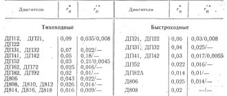
Table 6.1.