Color coding is an urgent need when installing electrical wiring. It allows you to find out why a particular cable is needed, and also reduces the likelihood of making mistakes during electrical installation and repair work. As a result, the likelihood of electric shock and short circuits is reduced. And if the switchboard is located in an apartment or private house, is it necessary to mark each cable? If the installation is carried out according to the rules, then this must be done. After all, in electrical panels the wire is designated by color not for beauty or for one’s own benefit, but primarily for those electricians who will subsequently repair and maintain this electrical panel or cabinet. Next, we will tell you how to mark wires and cables during installation in accordance with GOST and PUE.
Purposes of wire markings
The designation of cable lines and wires is carried out in order to simplify installation work, repairs and preventive maintenance of objects during operation. To improve safety measures that reduce the likelihood of accidents and injuries to operating personnel.
- the number and cross-section of wires in the cable;
- type of insulation;
- what metal are the wires made of?
- about the material of the outer insulation layer and much more.
All these measures are insufficient to achieve maximum safety and do not provide maintenance personnel with information about the purpose of cable lines and individual sections of electrical wiring. During installation in switchgears, additional markings are applied to cables and wires, which display not only the characteristics of the cable, but also its purpose in a given circuit.
A list of main parameters is indicated:
- cable brand;
- from what object does it come;
- length;
- appointment and other data as required.
To make marking convenient and quick, several methods have been invented for wires with different characteristics, diameters and insulation. Marker designs vary, but all provide clear, long-lasting writing.
Correct Conductor Identification
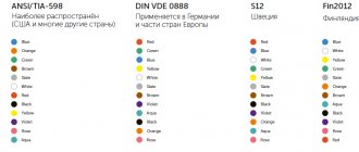
As I already wrote above, we take the latest GOST 33542–2015 officially implemented in Armenia, Belarus, Kyrgyzstan, Moldova, Russia and Tajikistan, then we find table A.1 there, which clearly regulates the colors, alphanumeric and graphic designations used for identification conductors and terminals of electrical equipment. And we use it!
Table A.1. Start. GOST 33542–2015
End of table A1 GOST 33542–2015
About IEC 60445:2017
This standard was released in August 2022 and replaced IEC 60445:2010, on the basis of which, as we know, GOST 33542-2015 was created. This standard has extremely important changes compared to IEC 60445:2010:
- the positive pole conductor is prescribed to be marked in red;
- negative pole conductor – white;
- functional grounding conductor – pink;
- Amendment 1, in particular, corrected two letter color designations in Table A.1. For brown color, the designation "BR" is replaced by the correct designation "BN", for gray color the designation "GR" is replaced by the designation "GY".
Wire and cable marking methods
Depending on the conditions and capabilities, availability of equipment and material, installers select the optimal marking options:
Before installing the wire
- PVC cambrics (tubes) of various diameters with inscriptions, you can additionally wrap them with transparent tape for reliable fastening and protection of the inscriptions;
- Heat-shrinkable insulating tubes;
- The most accessible and cheapest way is to make an inscription on a thick paper tag, place it on the cable and wrap it with transparent tape.
These methods ensure a tight fit to the cable sheath and eliminate the possibility of marker breakage when pulling through pipes and other installation work.
After installing the wire
When wires and cables are inserted into distribution devices, marking is done in the following ways:
- Before connecting the wires to the contacts, you can use PVC casings and heat-shrinkable tubes;
- Self-laminating markers are self-adhesive, on one side the plate is not transparent, on the other side there is a matte surface for inscriptions. The tag is glued to the wire insulation and wrapped with transparent self-adhesive tape, almost like tape. The materials of the plates and glue can withstand high temperatures and are resistant to aggressive environments.
- Tags are sometimes this method is the most optimal, they are made from polymers of different formats, several ways of attaching to the cable sheath. Plastic is able to withstand high temperatures while maintaining inscriptions on its surface. The dimensions of the tags and the content of the inscriptions comply with the requirements of the PUE, PTE EP, SNiP;
- For small-diameter wires, flags made of a polymer plate are used with inscriptions of standard designations, which are established by the guidelines for the design of electrical equipment;
- Self-adhesive nylon markers;
- Sleeves and containers consist of two components, a plastic carrier is attached to a wire (container), into which a polymer tape (marker) is inserted, and the necessary information is printed on it with a special printer;
- Clips and locking rings with pre-printed values, these can be individual numbers or letters, short content of 1-3 characters. This technique does not require the use of printing devices.
Rings RU Clips RA Clips R
| Type | Profile | Description | Dimensions |
| PA | Closed profile rings for medium and large diameter wires. | 4 sizes Ø 1.3 - 16.0 mm Section 0.2 - 70.0 mm2 | |
| PY | Closed profile rings for small diameter wires. | 1 size Ø 1.0-2.0 mm Section 0.2 - 0.7 mm2 | |
| PC | Open profile clips for fixed wires. | 5 sizes Ø 2.4-7.2 mm Section 1.0 - 10.0 mm2 | |
| PK | Rings for PKH plate with clamps (to be ordered separately). There is an analogue made of steel. | For wires and harnesses of any diameter |
Alphanumeric markers
Most of the cables have letters and numbers on their surface. Each is responsible for a specific function or purpose. Symbols are necessary because there are special regulations for manufacturers, confirmed by regulatory documents.
It is worth noting that in modern conditions everything is created not according to standards, but according to technical conditions. What will be written may vary greatly depending on the field.
Designation of markings of power cables and electrical wires and their interpretation
These models differ in their characteristics - they contain conductors with a cross-section that can power the equipment. But remember that such equipment includes household consumers and at the same time serious devices in enterprises with enormous power.
To correctly decipher the letters on the surface, we provide a small list:
- If it starts with marker A, then the main part is aluminum. The absence of "A" indicates a copper element.
- B – stands after A or first if there is no A. Indicates the presence of insulation around a live part.
- B - reports a PVC insulating layer, can appear after the previous characters or 1 in the list.
- P - means that there is rubber around the core. HP subtype - will not support combustion.
- P – is responsible for the polyethylene sheath; in the case of cable products, this is a thermoplastic variety. They write Ps if it is self-extinguishing, Pv if it is vulcanized.
- If AC or AA are combined, then the second symbol means aluminum winding, and C means lead winding.
- K – armored galvanized steel under the hose part, but it is designated this way only if the abbreviation does not begin with it. If this is the first character, then it indicates that we have a control cable.
- B features an armored section made of a steel plate. If it has the addition Bn, then it is armor with a non-flammable coating, otherwise there is no cushion.
- G – if the letter is large, it means that this brand can be installed even in mine workings.
- d – small indicates that there is sealing. Usually the sealing layer is made with water-repellent tapes. 2g is an aluminum polymer base.
- Shv, Shp and Shps indicate that the coating is made of PVC, polyethylene or non-flammable hose.
- O - signals that everyone will have their own shell.
- ng - symbolizes that the material does not burn and does not burn in any way.
- E - if it is at the very beginning, then this is a model that will withstand placement in a mine and with particularly aggressive conditions.
For control models
Able to transmit a control signal to any device to which it is connected. It is used when it is important to obtain accurate data.
Explanation of the designation of the cross-section of cables and various wires of this category:
- K – belonging to the control group. It can stand in either 1st or 2nd place, indicating the material of the core.
- A – indicates the presence of aluminum. If there is no symbol, then the option in front of you is copper core.
- B - denotes polyvinyl chloride as insulation near the live part.
- c – the outer side is made of the same material.
- P - makes it clear that the insulating element was formed from polyethylene.
- F – fluoroplastic layer.
- P - indicates the presence of rubber as an insulator. HP is a rubber shell that will not support combustion.
- G – confirms that the selected model is naked.
- E - if not at the beginning of the line, then this is the screen in the composition.
It is worth noting that the KG coding usually marks not the cord for controlling devices, but the flexible cable.
For contact
For these lines, they came up with special brands that have their own markings for cable products and electrical wires. In standard cases, these are examples for small current, which have a small cross-section and a large number of pairs.
Descriptions are registered on them:
- T – telephone;
- P – polyethylene insulation;
- p – waist insulating material made of PVC or polyethylene terephthalate;
- P - if they come in a row, then this is an additional protective shell;
- E – screen, this is one of the elements required for signalmen;
- Z - indicates that there is a hydrophobic filler that will retain penetrating moisture;
- C – used only on railways.
How to decipher a digital designation
Usually 3 digits are used, which take on the parameters:
- how many lived - there is 1 or many, each is marked;
- cross-section - if there are conductors with different indicators, they are marked separately;
- shows the nominal voltage, but it is not always there.
How wires and various cords are marked
The principle by which markers will be placed on them differs from that used for cables. All requirements are specified in GOST 7399-97.
In this area, AC will mean that it is an aluminum core with a steel core. We are not talking about isolation here.
Printing devices and instruments
To apply inscriptions to marking elements, special devices have been developed, which can be divided into several types:
Portable automatic and semi-automatic devices
Canon MK 1500 printer
One of the modern devices for automatic printing on stickers, PVC casings and heat-shrinkable tubes is the Canon MK 1500 printer.
It is possible to select several types of fonts and set cropping modes at different intervals. Printing speed is 2.5 cm per minute, on a 20 mm tube you can print 35 markers per minute with 5 full-size characters.
Hotmarker M-3E
The Hotmarker M-3E printer prints characters on cables, casings and flat tapes using the hot stamping method. The printer's heated dies press the ink into the cable sheath. The matrix has the shape of a wheel, on which there are 10 + space symbols, a total of 7 matrices, this allows you to form thousands of combinations. This printer is capable of marking products with a diameter of 13 mm.
Stationary printers
Brady LabelMark
Used in large-scale production where it is necessary to mark large volumes of products with different types of markers. Brady's software allows LabelMark to quickly change from one program to another. Within 6.5 seconds, it prints characters and sticks a tag on the cable.
The program is placed on a regular PC and transferred from it to the printer. To operate the program and operate the printer, no special highly qualified training is required. The device has a high print resolution, up to 300dpi, which allows you to print small fonts and clear images of logos. Symbols are applied to wires with diameters of 1.5-15.2 mm, maximum marker dimensions 50.8 X 50.8 mm.
| Specifications | ||
| Printing technology | thermal transfer | |
| Print Resolution | 300 dpi (300 dpi) | |
| Production cycle duration, seconds | 4,5 — 6,5 | |
| Minimum wire diameter, mm | 1,52 | |
| Maximum wire diameter, mm | 15,24 | |
| Maximum print width, mm | 50,8 | |
| Maximum print length, mm | 41,3 | |
| Maximum label width, mm | 50,8 | |
| Maximum label length, mm | 76,2 | |
| Minimum label width, mm | 6,35 | |
| Minimum label length, mm | 19,05 | |
| Ribbon outer diameter | 68.58 mm | |
| Fonts, Barcodes, Graphics | Printing fonts, barcodes and graphics are consistent with LabelMark™'s label creation capabilities . For more information on this issue, check out LabelMark™ software. | |
| Interfaces and connectors | USB, Serial RS-232C, Ethernet, PCMCIA, CompactFlash | |
| Memory | Built-in 4Mb Memory expansion 32Mb RAM using PCMCIA or CompactFlash® | |
| Dimensions, mm | 571.5 x 368.3 x 450.9 | |
| Weight, kg | 38,5 | |
| Operating temperature | from 10° to 41° C | |
| Storage and transportation temperature | -18° to 60° C | |
| Humidity | from 20% to 80% without condensation | |
| Nutrition | 90-264 V AC, at 47-63 kHz | |
Office laser printers
Used when printing on sheets of self-adhesive stickers or regular sheets of A4 paper. Tags are placed on the cables and wrapped with transparent tape. This is a simple and cheap way for small volumes of marking.
Tip #1. Do not buy expensive marking equipment if you are not professionally involved in electrical installation work. Use low cost labeling methods.
Basic requirements for marking wires in switchgears (switchgears) and switchboards
Clause 1.1.30 of the PUE states that all wires in the control panel must correspond to the alphabetic, digital and color designations. The presence of a color designation does not exclude the installation of numbers and letters. It is allowed to apply markings not along the entire length of the line, but only at the connection points.
Marking begins with compliance with the rules during the installation process, when connecting wires according to the color of the insulation. This is the most clear example, which allows operating personnel to quickly navigate the purpose of each individual wire in the circuit. Sometimes cables with wires of the same color are used; in these cases, it is possible to paint the ends of the wires, put on cambrics of the corresponding color, or it is more practical to install a heat-shrinkable tube with alphabetic and digital values already applied. The length of the marker tube must be at least 2.5 cm.
Wire marking by color
In three-phase networks, each phase is designated by the letters A, B, C, but in apartments and private houses single-phase power supply circuits are used, so there is no point in specifying which phase of the substation your panel is connected to.
Letter designations:
- The phase wire is marked with the letter “L”;
- The neutral wire is designated by the letter “N”;
- Grounding wires are marked with a symbol
- In circuits according to TN-CS system standards, it is allowed to connect the grounding conductor to the neutral wire. In such cases, “PEN” is written on the label.
- In DC power supply circuits, for individual consumer devices the polarities “+”, “-” and the voltage in volts “12V or 24V...” are indicated.
Marking DC circuits
What else is important to know
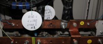
The photo below shows the board in which the wires were marked during installation:
When assembling an electrical panel, electrical wiring groups should be marked as follows: the input wire is marked as L, and the output wire is marked Gr (indicates that these are groups). After the letter the group number and line number are indicated.
Also, during marking, it is important to take into account all color differences so that an emergency situation does not arise. If, after opening the cabinet, no markings were found, then you need to use a probe to determine where each wire is located. We talked about how to use an indicator screwdriver to determine phase and zero in the corresponding article. Since this will take a lot of time, it is better to leave marks when checking so that another electrician who will carry out repairs or maintenance can understand where which wire is.
If there are no conductors of the required color, then you can use any color, as long as the ends of the cores are correctly marked during installation. This can be done using colored electrical tape or special heat-shrinkable tubes.
Heat shrink markings look like this:
This is the technology used to mark wires and cables when installing an electrical panel. As you can see, marking the lines is very important, and the process itself does not take much time. Please note that with the help of these instructions you can mark conductors not only in power electrical panels, but also in automation panels (for example, to mark signal cables and control).
It will be useful to read:
Features of digital wire designation
Digital designations in distribution boards require separate consideration. According to the requirements of the PUE, the distribution of power supply circuits in the distribution board is carried out in groups. Separate areas are fed from the group; these can be different objects:
- No. 1 lighting;
- No. 2 sockets;
- No. 3 air conditioner;
- No. 4 heated floors;
- No. 5 Boiler for heating water;
- No. 6 electric stove;
- No. 7 separate premises or structures (bathhouse, workshop, etc.)
In single-phase circuits, one phase L1-1 will arrive at the input of the circuit breakers; L1-2; L1-3, where 1,2,3 represent different lines. At the output of the switches, the wires are marked by group and line number, if there is one wire in a group, the marker writes Gr-1, if there are two Gr-1.2, indicating that this is the second wire of the first group.
Marking of wires in distribution boards by groups
On industrially assembled electrical panels, a connection diagram is pasted on the inside of the door indicating the markings of all wires; just to be on the safe side, you only need to sign the intended purpose. Wise people record this information on video or take photos during editing, save it on electronic media, even on social media servers. networks.
Tip #2. If you assembled the shield yourself or invited an electrician, such a diagram must be drawn up and glued to the door from the inside.
Stage 1. Laying cables
At this stage I stretch the cables from the shield to the boxes. As I wrote above, I wrap the ends with white electrical tape, on which I write the abbreviated name of the consumer (group) and put a serial number.
Signed cables arrive at the installation site of the shield
I carefully write down the name and number in the list near the shield.
List of consumer groups near the electrical panel (draft, if I had known that the photo would go to the website, I would have tried carefully))
Then it is better to duplicate this list in your notebook, since the rough draft on the wall may disappear when hard-working plasterers and painters appear.
The value of this list when the electrical panel is finally connected will be approximately the same as the value of the map in a pirate chest.
By the way, don’t be lazy (or instruct an interested person) to then transfer the names of power consumption groups to the panel, directly under each machine. This can be done with an ordinary thin marker, or you can go further - print the inscriptions on a printer. Otherwise, the leaf will definitely be lost, and in a year or two you will have to click the machines or ask the locals “What is this?”
Electrical panel with a leaf. Be sure to transfer the inscriptions to a permanent basis!
Features of marking of distribution boards and cables
According to the requirements of the PUE, the distribution devices themselves must also be marked; for apartments and private houses, the absence of names is allowed, due to the explicit definition of their purpose. When the shield is located outside the site on a power line pole or other structure, its marking must be indicated . It states:
- Manufacturer;
- Purpose and type of ASU, main switchboard, distribution switchboard, NKU;
- Voltage and current ratings;
- Degree of protection;
- There is a “Caution Voltage” sign on the doors;
- Lettering must be legible and environmentally resistant.
The following information is indicated on the markers of cables entering and exiting the distribution board:
- Poppy cable, it contains the number of cores, cross-section, metal of wires, insulation material;
- Cable purpose;
- Where does it come from?
- Where does it go;
- Length.
Tip #3. On the inside of the door there should be a detailed electrical diagram for connecting cables and the distribution of directions from the switchgear.
Checking the correctness of labeling
There are cases when the color marking is missing or erased, especially in old highways. To determine the phase and neutral electrical wires, you need a screwdriver with an indicator or a multimeter.
The blade of a screwdriver is placed against the exposed wire to reveal the live wire. If the light in the handle lights up, the wire is under load. The neutral conductor will not give a signal in the form of a lit indicator.
A multimeter is used to find the ground contact. The device is set to 220 V. One contact is connected to the phase, the other in turn to the others. When it hits zero, the device will show a voltage much lower than 220V. This is how they work when determining the voltage in household AC wiring.
When working, you must not grasp the barrel of the screwdriver below the handle, as this could result in an electric shock if the wire being tested is live. The finger is placed on the metal plate at the top of the screwdriver handle.
Common labeling mistakes
- The most common mistake made by novice installers and experienced ones due to inattention. When the wires in the shield are screwed onto the terminals without first putting on labeled casings or heat-shrinkable tubes. Then you have to unscrew and put on the marking elements.
- They confuse the “PEN” conductor with the grounding wire, they have the same color markings, you need to look carefully.
- If the panel is located outside the site, but is on your balance sheet, this is determined by an agreement with the energy supply organization. It is imperative to have technical documentation of the circuit for it, and to fulfill all the requirements of the PUE, PTEEP and other documents. There may be claims from Rostechnadzor, up to disconnection of the consumer and fines.
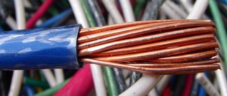
Ground wire color
From 01/01/2011 the color of the grounding (or grounding) conductor can only be yellow-green. This color marking of wires is also observed when drawing up diagrams on which such conductors are signed with the Latin letters PE. The coloring of one of the conductors on cables is not always intended for grounding - usually it is done if there are three, five or more conductors in the cable.
PEN wires with combined “ground” and “zero” deserve special attention. Connections of this type are still often found in old buildings, in which the electrification was carried out according to outdated standards and has not yet been updated. If the cable was laid according to the rules, then blue insulation was used, and yellow-green cambrics were put on the ends and joints. Although, you can also find the color of the grounding (grounding) wire exactly the opposite - yellow-green with blue tips.
The grounding and neutral conductors may differ in thickness; they are often thinner than the phase conductors, especially on cables that are used to connect portable devices.
Protective grounding is mandatory when laying lines in residential and industrial premises and is regulated by PUE standards and GOST 18714-81. The neutral grounding wire should have as little resistance as possible, the same applies to the grounding loop. If all installation work is carried out correctly, then grounding will be a reliable protector of human life and health in the event of a fault in the power line. As a result, correctly marking cables for grounding is critical, and grounding should not be used at all. In all new houses, wiring is done according to the new rules, and old ones are put in line for replacement.