GM328 review
Here's what it can detect and measure characteristics:
- NPN and PNP transistors
- Mosfet
- Diodes
- VEL
- Double diodes
- Thyristors
- Zener diodes
- Resistors (maybe two at a time)
- Capacitors
- DC voltage up to 50 volts
Impressive, isn't it? Shows ESR and gate capacitance for each monitored element. In addition, it can be used as a pulse generator from 1 Hz to 2 MHz and also to measure frequency in the same range. And these are just the main features. Excellent color graphics display, sharp and bright. The basic firmware has the ability to customize colors for each interface element.
I would also like to note the possibility of reflashing this tester, because we always want to improve or redo something). Fortunately, there are a lot of firmwares for this model on the Internet, including Russian ones. I will definitely write a detailed manual on the firmware in the near future.
Types of tested elements:
| element name | display indication/range |
| NPN transistors | "NPN" |
| PNP transistors | "PNP" |
| N-channel-enriched MOSFETs | "NE-MOS" |
| P-channel-enriched MOSFETs | "PE-MOS" |
| N-channel-depletion MOSFETs | "ND-MOS" |
| P-channel-depletion MOSFETs | "PD-MOS" |
| N-channel JFETs | "N-JFET" |
| P-channel JFETs | "P-JFET" |
| Thyristors | "Tyrystor" |
| Triacs | "Triak" |
| Diodes | "Diode" |
| Dual-cathode diode assemblies | "Double diode CK" |
| Double-Anode Diode Assemblies | "Double diode CA" |
| Two diodes connected in series | "2 diode series" |
| Symmetrical diodes | "Diode symmetric" |
| Resistors | from 0.5 K to 500K |
| Capacitors | from 0.2nF to 1000uF |
Cable tester
When measuring resistance or capacitance, the device does not provide high accuracy Description of additional measurement parameters: - H21e (current gain) - range up to 10000 - (1-2-3) - order of connected element terminals - Availability of protection elements - diode - “Diode symbol " - Forward voltage - Uf - Opening voltage (for MOSFET) - Vt - Gate capacitance (for MOSFET) - C=
The author of the device was Markus, but later development was continued by Karl Heinz.
Well, what can we say, it determines transistors and diodes, the capacitance of capacitors too, electrolytes and ESR shows. I can’t say anything about the accuracy of the measurements yet; I don’t have time to verify the readings yet. The tester turned out to be not very easy to use.
Typical examples of using an LCR meter and a transistor tester for checking radio components
Resistors are the most common type of radio components
Wirewound resistors with different power ratings
| If there are no problems with common values, measuring low resistance resistors can complicate the task. An ordinary multimeter can often measure normal resistance of the order of 1-2 Ohms and higher, if lower, then the resistance of the wires, probes and low resolution begin to greatly influence. Even the fairly accurate UNI-T UT61E has a measurement resolution in this mode of only 10 mOhm, while even an inexpensive LCR meter has a minimum resolution of 0.1 mOhm. | Digital multimeter UNI-T UT61E high accuracy with the ability to connect to a PC to delete logs |
Accordingly, if using a multimeter you can relatively accurately measure resistors with a resistance of 0.05-0.1 Ohm, then when measuring 10 mOhm you will actually not measure anything; for comparison below - measuring two resistors with a nominal value of 1 and 2.2 mOhm.
Difference between multimeter and RLC tester readings when measuring low resistance resistors
Low resistance measurements are often required when testing, sizing or manufacturing current sensing shunts. An alternative option for measuring voltage drop, but requires an adjustable power supply, ammeter, voltmeter.
The current shunt is a low resistance resistor which is a low resistance resistor
The ability to measure low resistance is also useful for detecting problems such as marking errors, especially low resistance resistors.
The resistor on the left is labeled as 0.1 ohm, on the right as 0.22 ohm, but in reality they have almost the same resistance. Such mistakes can sometimes be very costly.
Before installing or soldering a resistor in a circuit, check its resistance. Make sure the nominal and actual values of the resistor are the same
Transistors
Measuring low resistances will help evaluate the originality of field-effect transistors. Currently, more and more counterfeit and relabeled transistors are appearing on the market. While simply measuring resistance doesn't give you the full picture, it does give you a quick idea of what's in front of you.
For the test, in addition to the device, a 9-volt battery is sufficient. Datasheets often refer to a gate voltage of 10 volts, but this is not relevant in this case. In addition, it is correct to measure the drain-source resistance by current; it is usually indicated in the documentation, but for this you need at least a laboratory power supply.
To test the transistor: we connect test probes to the drain and source terminals (usually the center and right), and apply 9 volts to the outer terminals. A constant application of voltage is not required, it is enough to charge the gate capacitor, but you must be careful not to accidentally connect the battery to the tester probes. You can also “load” the transistor first, and only then connect the probes.
Checking a MOSFET field-effect transistor with a tester
Capacitors
Capacitors are used somewhat less frequently, but have their own characteristics. For example, unlike resistors, they are much more susceptible to aging, especially when it comes to electrolytic capacitors installed in switching power supplies, motherboard converters, etc.
Film, ceramic, electrolytic capacitors
The ESR of capacitors is of particular importance. When a capacitor dries out with almost no loss of capacity, its internal resistance increases significantly.
This cannot be diagnosed with a conventional multimeter; you can change everything, but this is not always convenient, often difficult or expensive. Additionally, RLC meters often allow measurements to be made without desoldering the component, although this of course depends on the wiring diagram.
- Most multimeters measure the capacitor as ideal, that is, without taking into account its features, sometimes this is enough, sometimes not.
- The most sophisticated devices can separate a capacitor from its internal resistance, and also measure these parameters separately.
- The equivalent circuit of a capacitor looks much more complex - all these parameters can be measured, but this is a completely different class of devices that ordinary radio amateurs usually do not need.
Equivalent series circuit, where R is the electrical resistance of the capacitor insulation, responsible for the leakage current, and the equivalent series resistance; L—equivalent series inductance; C - capacitance of the capacitor
For example, a comparison of two capacitors, cheap and branded Chinese. Although accurate, a conventional multimeter considers them almost identical, showing only a slight difference in capacitance. But if you connect the capacitors to an LCR meter, you can see that the difference in their internal resistance is almost 5 times! If you plan to use capacitors when switching power supplies, it is this difference in resistance that will affect heating and, as a result, the service life and characteristics of the power supply. Capacitors with high internal resistance cannot effectively suppress peaks.
Capacitance and ESR measurement of electrolytic capacitors
Chokes and inductors
Reactors, transformers, and winding units in general, unlike capacitors and resistors, are even more difficult to control, and typically a multimeter can measure inductance.
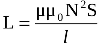
The main characteristic of the narrowing is inductance, that is, a coefficient that determines the dependence of the rate of change of electric current on the voltage on the coil
An impedance meter makes it easier to make winding units, as well as search for short circuits between turns. By comparison with a good component or a known value, it can be realized that the transformer or inductance is faulty as its inductance will change greatly.
Electrical monitoring of inductors includes detection of turn short circuits (short circuits between winding turns). If there is a two-turn circuit in the studio winding, then its inductance will drop sharply.
Typically, there are indicators to look for shorted traces, but an impedance meter will also detect this problem. For example, on the left there is a working transformer, on the right it is the same, but with a shorted turn. It can be seen that the winding inductance has become significantly smaller, and the turn also affected the result of measuring the active resistance of the winding.
Comparison of the inductance of a working transformer and a closed-loop transformer
If your feet smell bad, remember where they come from.
After googling a little, I found a diagram of a device for testing transistors , which has been replicated on quite a decent number of sites. Simple, portable... but no one except the author himself praises it. This should have been confusing right away, but alas.
So, the original circuit (with slightly simplified indication and switching):
Click to enlarge
According to the author's idea, here the operational amplifier together with the transistor under test forms a source of stable current. The emitter current in this circuit is constant and is determined by the value of the emitter resistor. Knowing this current, all we have to do is measure the base current, and then by dividing one by the other, obtain the value h21e. (in the author’s version, the scale of the measuring head was immediately calibrated in h21e values).
Two bipolar transistors at the op-amp output serve to increase the load capacity of the microcircuit when measuring high currents. The diode bridge is included in order to eliminate the need to reconnect the ammeter when switching from “pnp” to “npn” transistors. To increase the accuracy of selecting complementary pairs of bipolar transistors, it is necessary to select zener diodes (setting the reference voltage) with the stabilization voltages as close as possible.
I was immediately confused by the “not entirely correct” switching on of the operational amplifier with a single-supply supply. But the breadboard will endure everything, so the circuit was assembled and tested.
Shortcomings immediately emerged. The current through the transistor was highly dependent on the supply voltage, which is not at all reminiscent of a stable current generator . What the author of the circuit managed to select, while powering the device from a battery, remains a big mystery. As the battery discharges, the “exemplary” current will flow away and quite noticeably. Then I had to tinker with the “amplifier” at the op-amp output, otherwise the circuit would work unstably when measuring transistors of different powers. It was necessary to select the value of the resistor, and then I switched to a more “classical” version of the amplifier. And the bipolar (correct) power supply of the op-amp solved the problem with the floating current.
As a result, the diagram took the form:
Click to enlarge
But here another drawback has emerged - if you confuse the conductivity of the bipolar transistor (turn on “pnp” on the device, and connect the “npn” transistor), and when selecting from a large number of transistors, you will definitely forget to switch the device sooner or later, then one will fail from the transistors of the “amplifier” and you will have to repair the device. And why do we need difficulties with bipolar power supply, opamp, amplifier, etc.?
Examples of measurements of radio components
Using a radio element meter is very simple. You need to install the part and turn on the device. He will check the power supply, if it is normal, he will start checking the part installed in the connectors. Based on the test results, a message will be displayed indicating the type of part and its parameters.
Branded device
To make it clearer, let’s look at the work of the popular clones M328 and GM328. The difference between them lies in the set of possible functions (the GM328 has more of them). Any device is turned on by briefly pressing the handle. Pressed, held for 1-2 seconds and released. The device turns off either by selecting the appropriate line in the main menu (Switch Off) or by holding the knob pressed for 10 seconds.
Instructions for safe use
As a rule, the instructions for safe operation are common for all devices. Before starting work with the tester, you must put on personal safety equipment. Then study the instructions for the specific current switch that needs to be tested. Next, you need to press the current or short circuit switch button, insert the probe to the phase output, and connect the other to the grounded contact of the device under test. Then you need to click the test button and find out the data.
Note! It is important that ungrounded contacts cannot be tested. It can be life threatening
Instructions for safe use
In general, a voltage tester or multimeter, according to modern terminology, is a multifunctional device aimed at testing any electrical equipment. It comes in different types and is marketed with different features. Allows you to test capacitance, inductance and transistor in many cases. Works properly for many years according to instructions. It does not require special care.
M328 operating modes
After turning on the device, you can view all operating modes. In the GM328, switching to the menu is done by pressing the knob (gear shift knob). Press and hold for 3-7 seconds (different assemblies vary). After releasing the handle, a menu appears. Typically it consists of the following points:
- Transistor is the main mode of operation of the device, in which all radio elements are checked, with the exception of capacitors.
- C + ESR @ TP1: 3 - mode for measuring capacitance of capacitors and ESR parameters.
- Contrast: Adjust screen brightness, adjust contrast.
- Frequency - measurement of the frequency of alternating voltage.
- f-Generator: works as a square wave generator.
After turning on the device, go to the main menu. There you can select its operating mode
- 10-bit PWM: Generates square wave pulses, works as a PWM signal generator.
- rotary encoder - simulator of encoder operation.
- Self-test - calibration.
- Show data—view information in memory (last measurements).
- Power off—turn off the device.
The active mode is marked by the M328 universal radio component tester with a checkmark in front of the line with the name of the element. Even highlighting or highlighting is possible. Move through the menu by turning the knob. Switching / activating the selected mode - short press the handle. Do not overdo it, otherwise the device will reboot.
Usually it is left in transistor mode. This mode starts automatically when the device is turned on. Everything can be measured in it. Many models also have capacitors. And only some require switching to a special mode.
Additional GM328 assembly modes
The installation option for the GM328 universal radio-element meter has more possibilities. It has specialized modes for testing resistors, capacitors, decoders and encoders. It can also work as a voltmeter. Another 10 are added to the above items which are listed below.
- RL - inductance.
- C. Capacity.
- DS18B20. Interpretation of temperature sensor readings.
- C (mF) - correction (large capacitors).
- IR_Decoder. IR protocol signal decoder.
Checking the power status every time you turn on
- IR_Encoder. IR protocol signal transmission.
- DHT11. Interpretation of temperature and humidity sensors.
- Voltmeter - Voltmeter.
- FrontColor - Text color.
- Background color. Background color.
Are these special modes necessary? If you are a professional technician, then yes. They are not needed for home use. All you need is simpler assembly.
Appearance of the device
An electronic tester is a small device with a display, an encoder button and a special contact pad for connecting electronic components (ZIF panel).
Cheap testers have simple text displays that display only basic information; more sophisticated ones are equipped with a graphic display displaying icons of elements. More information can be placed on such a screen. The ZIF panel is made for convenient fastening of the contacts of the element being measured.
The button serves to turn on and simultaneously measure the nominal value of the element; in more expensive models, there is also an encoder for moving through the menu, selecting options, and fine-tuning the device.
Capabilities of the universal tester
This device is called a transistor tester as it is one of the most requested features. But this is only one line from the list of possibilities. You can also find the name Markus tester, universal or multifunctional tester, radio component meter, multitester, ESR tester and many other more or less similar options. And all because he can do a lot and everyone names them in accordance with the functions that are important to him. Here is a sample list of possibilities:
- Check the capacitance of any type of capacitor.
In addition, it also sets additional parameters - ESR - capacitor resistance and Vloss - voltage drop, which is displayed as a percentage. In fact, the last parameter reflects the degree of “wear” of the capacitor (in particular, drying out of the electrolyte). The higher the number, the worse. This is how it outputs transistor measurements/test results - Check the transistors smoothly, determine the pinout. Describes which terminal the cathode-anode base is connected to. The gate opening threshold voltage value can be specified.
- It can be used as a generator of a given frequency.
- Some allow you to measure frequency, time parameters of sinusoidal voltage, parameters of rectangular pulses.
- They can control temperature sensors (for heated floors - a very useful, but rare option).
Check the serviceability of LEDs, diodes, triodes, optocouplers. Determine the gain, pinout.
, ready-made or designer
You can buy a universal radio component tester from a brand or one of the Chinese clones. The difference in price is more than noticeable. But the reliability and accuracy of branded devices are guaranteed, and, fortunately, with clones.
Externally, there is a significant difference between a brand and a clone
The well-known Ali has universal testers for radio components with and without a case. Without a case, of course, it’s cheaper. Chinese meters with a case are quite inexpensive (about 20-30 dollars), and without a case they are even cheaper. But many suffer from unreliability: they lie firmly. You have to rely on reviews.
Set of parts - constructor for assembling a universal meter for parts parameters
Although ready-made semiconductor testers are cheap on Ali, there is an even cheaper option - the so-called assemblers. A universal meter manufacturer is a PCB and a set of parts that you need to install/solder yourself. Initially, select a set of functions. Below this, a series of parts will be sent to you. Some complex parts (microprocessor) may already be installed. The rest - capacitors, resistors, capacitors, etc. - will need to be soldered yourself.
Disassembly
Disassembling the device is quite trivial, unscrew 4 screws and you're done:
Inside we are greeted by the same Atmega 328R:
Composition of the GM328 construction set
GM328 + TFT radio component tester circuit
Actually, to assemble this device we will need at least a simple 25 W soldering iron with a thin tip and solder, provided that the Chinese sent you a complete set). Of course, participation from a third party, card clip, or like-minded person in the assembly process is always welcome. To assemble the GM328 radio component tester, you don’t even need straight hands; the process is so simple that even a novice radio amateur can handle it, which the latter can only be happy about. If you have become the owner of a complete kit for assembling our device, you should have the following items on your table:
Contents of the kit for installing the radio components tester GM328
GM328 Transistor Tester - Kit Contents
- 1 PC. - board with tracks, partial holes and many SMDs
- 1 PC. - color graphic display
- 1 PC. — DIP panel for microcontroller
- 1 PC. — microcontroller Atmega328p 16-PU with basic firmware
- 1 PC. - 8-foot pin connector for display connection
- 1 PC. - 8-foot pin connector for display connection
- 3 pcs. - two-screw terminals
- 25 pcs. - resistors of different power
- 1 PC. - quartz
- 1 PC. - zener diode
- 3 pcs. - transistor
- 1 PC. - varistor
- 1 PC. - Light-emitting diode
- 1 PC. — ZIF panel for connecting the measured radio component
- 2 pcs. - electrolytes
- 9 pcs. - ceramic capacitors
- 1 PC. - socket
- 1 PC. - crown connector (not always)
- 1 PC. - encoder
Unfortunately, I came across a kit with a torn VO5 chip
Sometimes it happens)
So I still had to resort to using a soldering station to solder this little SMD. And here is the result of the work:
Few direct hands)
Main causes of malfunction
The most common reasons for a triode element in an electronic circuit to fail to operate are as follows:
- Break in the transition between components.
- Breakdown of one of the transitions.
- Breakdown of the collector or emitter section.
- Power leakage under voltage.
- Visible damage to the terminals.
Characteristic external signs of such a breakdown are blackening of the part, swelling, and the appearance of a black spot. Since these shell changes occur only with high-power transistors, the issue of diagnosing low-power ones remains relevant.
Source
Review of features, main technical characteristics and capabilities of LCR parameter meters
We compare several meters of different prices, evaluate their advantages and disadvantages.
Markus transistor tester with AVR microcontroller
| Let's start, of course, with the famous transistor tester Marcus. It exists in various versions: with or without a housing, with a built-in frequency meter, with testing zener diodes, homemade or factory-made. It is sometimes mistakenly called an ESR meter - this is not entirely correct, since it was originally a transistor meter, and ESR measurement is just one of its functions that was added much later. In addition, the device has a very large community on the well-known website vrtp.ru, where you can find out how to flash a transistor tester. | Transistor tester TC1 |
| Transistor tester LCR-T4 |
Popular transistor testers EZM Electronics MK-168 and M8
Perhaps this is really a solution for a beginner - such a tester is capable of measuring many different components. It is especially convenient to check transistors, for example, to facilitate such a task as searching for the emitter-collector base of a transistor. Testing capacitors with resistors is also a good idea.
Component testing on GM328
But more importantly, this tester can measure capacitance and inductance and perform a complete measurement. That is, for example, for inductance it shows not only the inductance, but also the active resistance of the winding, and for capacitors not only the capacitance, but also the internal resistance.
Of course, there are also disadvantages; due to the simple circuit and two-wire connection of the component, it is unlikely that it will operate with low resistances.
GM328 Component Testing - Continued
LC meters
The next step is to take devices up a notch: LCR meters. They cannot test transistor parameters, but they will measure inductance or low resistance better than a universal tester. A typical representative is Juntek LC100-A.
Unlike the previous device, the ESR tester firmware is closed, so there is no upgrade option available.
LC meter, capacitance and inductance meter LC100-A
Such meters have the disadvantage of a universal device - a two-wire connection. Therefore, the measurement result can be greatly influenced by the quality of contact with the component and the length of the wires. Calibrating the ESR tester, of course, solves the problem of wire length, but it is better to use wires of minimal length and large cross-section.
LCR+ESR meters
For the more experienced, there is a device, albeit unprofessional, but definitely close to them: this is the XJW01. In addition to standard measurements, it allows you to perform complex measurements, as well as measure the quality factor of dielectric losses. The tester has a four-wire connection.
The XJW01 allows measurements at three frequencies: 100 Hz, 1 kHz and 7.8 kHz. The XJW01 is sold as an installation kit or as a complete unit.
Q-meter XJW01 for measuring quality factor, loss factor
The tester can operate both in automatic mode for selecting the measured value, and in manual mode. It is better to use manual mode, since automation sometimes incorrectly determines the type of component.
XJW01 is used to test any passive component
The presence of a four-wire connection immediately puts the XJW01 head and shoulders above many other amateur devices: such a connection allows you to separate the circuits of the current generator and the measuring part, due to which the length of the wires and contact resistance no longer affect the measurement results.
This type of connection is used in professional devices: even if the component is connected directly to the terminals of the device, a special contact group consisting of four contacts is also used.
Immittance parameters of HIOKI radio components
Clamps, tweezers or remote pin kits are used to connect radio components, and since they also use BNC connectors for connections, even branded devices are compatible with the XJW01 shown above.
Test device and 4-wire test probe
In fact, the same is true with branded, but relatively inexpensive LCR meters from UNI-T and Hantek. They also have four-wire connection, capacitance, inductance and resistance measurements, including ESR and complex measurements.
Particularly noteworthy is the new model of the Hantek 1832C meter, with which you can take measurements in seven frequency options with an upper limit of 40 kHz. The main error is up to 0.3%, there is an automatic measurement mode, complex measurement modes.
There is an older model in this series - Hantek 1833C, which has an extended frequency range, but is expensive.
Hantek 1832C has a large screen on which all test results are displayed simultaneously. The component under test is connected using two and four wires (three and five, taking into account the protection contact).
The test signal swing is 0.6 volts, which makes it possible to measure many passive radio components without decoupling from the board.
Declared ranges of measured parameters:
- Inductance - up to 20 H;
- Capacity: up to 20000 uF;
- Resistance - up to 20 MOhm;
The Hantek 1832C portable RLC meter offers advanced features of a modern device that allows you to measure components accurately, quickly and conveniently
However, modern devices can often measure at frequencies up to 100 kHz (for example, Hantek 1833C), which allows you to test components at a higher level. This is especially helpful when selecting capacitors for use in switching power supplies whose operating frequencies are comparable.
But you have to be careful: many LCR meters often have a stated frequency range of up to 100 kHz. However, if you carefully read the instructions, it will become clear that in the measurement mode at this frequency, the maximum measured capacitance is significantly less.
For example, the CEM DT9935 instruction at 10 kHz can measure up to 200 µF and 100 kHz, only up to 2 µF
What it is
A transistor tester is a universal digital measuring device that can test not only transistors, but also other elements. Both semiconductor elements - thyristors, triacs, diodes and others, as well as passive elements, for example: resistors, capacitors, inductors.
However, in most cases, it is more convenient and faster to check the above elements for serviceability with a multimeter, but this device is still useful as an ESR tester.
Read also: How to check varicap with a multimeter
ESR is equivalent series resistance, an important parameter for electrolytic capacitors. Due to the impossibility of measuring it with a household multimeter, and specialized ESR meters are expensive, it is much more difficult for beginners to diagnose faults in electronic circuits.
With the help of transistor testers, you can measure ESR with normal accuracy, and the cost of these devices is in the range of 10-20 dollars, depending on the model.
This device is often called the "Marcus Transistor Tester", which is partly incorrect. Initially, the idea to create a universal tool for testing radio components originated with Markus Frejek, and later his work was continued by Karl Heinz Kubbeler. And the so-called transistor testers from aliexpress are nothing more than copies of the Marcus tester, devices modified by enthusiasts. Therefore, they do not have a specific manufacturer, but they have a wide community on the Internet. Thanks to this, it is easy to find Russian-language firmware and instructions for upgrading the device.
Calibration
When running the Universal Radio Component Tester for the first time, calibration may be required. If there are instructions, you just need to follow all the steps point by point. Nothing complicated, simple steps, but without them no one can guarantee the accuracy of measurements.
Calibration message
If there are no instructions, you can read the on-screen prompts. Messages are usually in English and are displayed sequentially.
Example of calibration of the GM328 universal tester
Since English is not accessible to everyone, we will give an example of calibration of the Chinese “manufacturer” GM328. This is one of the most popular builds and costs about $12.
To calibrate the GM328 Universal Tester, connect all three measurement pins (areas) using jumpers. It is convenient to make two U-shaped jumpers, the first connects 1-2, the second 2-3. You can make one in the shape of the letter S. The procedure is as follows:
- Turn on your device. Turn on the GM328 by briefly pressing the encoder (some call it encoder).
Go to self-test mode. Because of this:
- As soon as any message lights up on the screen after startup, press the knob again and hold it for 7-8 seconds. Neither more nor less, since at another moment of pressing, a reboot will occur or the device will turn off.
- If you release the handle after 7-8 seconds, the main menu will appear on the screen. It is necessary to switch from the current mode to the self-test mode - “Self-test”. The current mode is highlighted in green or with a check mark (as in the photo). Turn the knob to change position. If you need to go down further, go clockwise
This is the main menu. To calibrate, you need to go to self-test mode - Selftest
- When the desired line is marked, press the knob to confirm your selection.
- After starting the test program, the message Short Probers appears - short test (you will cover all measurement areas with jumpers). It burns for about a minute. During this period, it is necessary to install jumpers.
Requirements for the installation of jumpers and the result of testing the short circuit resistance between measurement zones
- Once the jumpers are inserted, a series of numbers will appear. This is the resistance of the jumpers installed between the contacts.
- After this message is displayed, Probersa Island is displayed. This means that the insulation between the test pins will be further checked and the jumpers must be removed.
When this message appears, the jumpers must be removed
- After removing the jumpers, the following two messages are displayed. They are informational in nature: they show the insulation between the contacts.
This is the measurement area insulation test data
- Then a message appears indicating that it is necessary to install a capacitor with a capacity of more than 100 µF. Its legs need to be inserted into pins 1 and 3. Without this step, the calibration will not be completed. And a message about its necessity will appear before each measurement, which is terribly annoying. Note! The capacitor for calibration must be a sheet capacitor. As a last resort, it is strictly not recommended to use ceramics and electrolytes.
This type of message indicates the need to install a capacitor larger than 100 nF
- Once a capacitor of sufficient capacity is installed, the “Test End” message will appear and the device will continue to operate without annoying messages.
This is an example of calibrating a specific universal radio component tester. This doesn't mean that others will have the same experience. But at least you will have an idea of what may be required of you.
Inconveniences when using:
- For each measurement, you must first place the part on the contact pads, and then press the “Test” button, and the time elapses from the moment of switching on to the measurement is not so short.
- If the component under test burns out with a short circuit of all three legs, then in this case the tester will go into self-test mode.
- No indicator light. I suspect that the rightmost two pins on the indicator board were simply not soldered. By the way, they are labeled “A” and “K”.
- The LED indicating the device is turned on is very bright.
- The tester is loaded with an old program; on specialized forums, there are newer ones that more conveniently show the pinout of the component along the legs.
- It’s unclear what the two terminals are; you can’t clamp the wire into them. Only pins.
And here is the board itself, the Mega markings have been scraped off.
And here is the unsoldered part of the board. It showed a circuit diagram of a module that ensures the tester operates from a lithium battery.
The actual name of the edition is “Booster edition”.
Checking parts with a universal tester
We insert the legs of the parts in two different areas. After a few seconds we see the measurement results on the screen. The type of element is indicated (a graphic image is drawn), which includes pins, its value is indicated, indicating the size and units of measurement, additional parameters, if any.
Checking resistors and capacitances
The photo shows the measurement results of two resistors. Of course, they can be checked with a multimeter, but that’s also quick and easy. This feature can be used if color coding is still poorly implemented.
Examples of measurements with a universal resistance meter
To change parts, simply take one out and put on another. It doesn't matter what kind of nests. The measurement of the installed element begins after a short press on the handle. We changed the resistor, pressed it, and got new measurement results. Without pressing, the old data remains on the screen. If no action is taken for a long enough time (about 30 seconds), the device turns off.
An electrolytic capacitor and the result of its measurements are installed in the measuring sockets
the same goes for capacitors. Simply insert your feet into the measuring unit and press the handle.
Note! Electrolytic capacitors must be discharged before testing. Or you need to buy a new device.
How to test diodes and zener diodes
You can check the diodes with a universal meter. Some, such as Schottky diodes, may not test all models. If you are working with such special radio elements, make sure that the type of diodes you need is indicated in the description.
Results of checking diodes with a universal tester
When checking diodes, the type (schematic representation) and to which pins it is connected are also indicated. Shows the voltage drop, and in the junction - reverse current and capacitance (apparently parasitic).
Checking the Zener diode
When measuring zener diodes, it also shows the reverse breakdown voltage. It is difficult to check this parameter with a conventional multimeter. Most likely, this is not always possible. Many devices simply cannot “break through” the barrier.
How to measure transistors
Transistors can be small, with short legs. They are installed on two measuring platforms.
Transistor tester determines pinout and all parameters
It shows the pinout, i.e. to which input the emitter, collector, and base are connected. The type is indicated: NPN or PNP, transient currents and voltage. If the transistor is broken, it is called low resistance.
Nuances
When using, you should remember the nuances and limitations of most transistor testers:
- Powerful thyristors can be recognized as faulty or as transistors.
- Zener diodes. Defines as diodes. The manufacturer claims normal recognition of elements with a stabilization voltage of less than 4.5V.
- Microcircuits and three-legged integrated stabilizers (7805, 7905 and similar) are not identified or checked.
- It does not check dinistors because of their high operating voltage, for example, for the common DB3 it is more than 30 Volts.
- It also does not recognize large-capacity capacitors, although the manufacturer claims measurement limits from 30 pF to 100 mF, “adequate” values are given up to a couple of thousand μF.
- Inductance is measured in the range from 0.01 mH to 20 G.
- Does not recognize ionistors.
- Varistors are seen as capacitors.
- Unidirectional suppressors are defined as diodes.
- No input protection. This means that you can burn out the input if you start measuring a charged capacitor, for example, or apply high voltage. Therefore, discharge the capacitors.
Read also: Flea market 23 state numbers
If you want to test a component, but it has short legs, then you can check it on the LCR-T4 tester by placing them on the SMD pad.
In general, the device has found wide application and will be especially useful for beginning radio amateurs when purchasing their first equipment for a home laboratory. If you take into account the cost of the device, then you can put up with all its errors and shortcomings, at least for the sake of the convenient function of determining the pinout and determining the ESR of electrolytes when diagnosing power supplies.
Now you know what a transistor tester is, how to use it and what this device is intended for. If you have any questions, ask them in the comments below the article!
During the repair of various household equipment, we had to deal with malfunctions associated with changes in the parameters of electrolytic capacitors. A simple multimeter or dial gauge can only identify broken or short-circuited capacitors. The multimeter attachment, which I also assembled, only determines their ESR. Therefore, I ordered a semiconductor tester + LC + ESR meter from China. Although, with good knowledge, you can assemble a similar device yourself.
We were pleased with the very modest dimensions of the device (72*62.5 mm). The height is determined by the height of the “Crown” - 17.5 mm. When turned on, the indicator displays information about the state of the battery and the absence of a radio component in the block. Below, many of the photos are in high resolution - you can click on them to see the details better.
It must be said that the device is very demanding when it comes to nutrition and eats a lot of it. My specimen, at a voltage of around 7.5 volts, briefly retreated into itself and refused to take measurements. Having replaced the crown, I immediately felt the difference between amateur radio before and after)). In the future I plan to get rid of the crown altogether. I want to build a power unit based on a boost converter, a lithium battery and its charging controller. The screen has a resolution of 128*64. The device allows you to measure both lead radio components and SMD, for which there is a special platform between the block for lead parts and the button. A tester was built based on the Mega 328 microcontroller.
The testing time for radio components is around 2 seconds, only for large nominal capacities – up to one minute. The device itself was associated with cases of changes in the parameters of electrolytic capacitors, as a result of which the circuits where they were installed behaved inadequately. If an electrolytic capacitor is installed in the tester block, the device simultaneously measures its capacitance and capacitor reactance - ESR, as well as Vloss - leakage voltage (in percent). The results obtained are compared with the table ones.
Table of EPS capacitors
If the measurement results exceed the table value by more than 10%, I send the electrolytic capacitor to the bucket.
Capacitor 330*25 volts
Capacitor 10 uF * 50 volts
Capacitor 33 uF * 50 volts
Capacitor 47 microfarads * 160 volts. I stood in the “cold” part of the TV’s power supply and warmed up. Goes in the bucket
The 220 microfarad capacitor * 35 volt is also sent to the trash heap
For non-polar ones, the ESR value will always be more than 10 Ohms. The capacitor measurement range is from 25 pF to 100,000 µF in 1 pf increments.
Capacitor 0.1 uF
Capacitor 3900 from an energy-saving lamp unexpectedly produced 991 picofarads. After replacing it, the lamp resumed working
68 nanofarad capacitor
Metal paper capacitor MBM 0.1 uF completely unused, but after years of storage with far advanced parameters (((.
Vloss value (leakage voltage immediately after the capacitor has stopped charging) of several percent indicates a faulty capacitor. For myself, I determined the serviceability level of an electrolytic capacitor based on the leakage voltage parameter of 3%.
Before testing, all capacitors must be discharged - otherwise there is a high probability of the tester failing.
Resistances are measured in the range from 0.5 Ohm to 50 MOhm in 0.1 Ohm steps. Inductors are tested in the range of 0.01 mN - 20 N, with their resistance displayed.
Resistor 1.3 kOhm
Resistor 200 kOhm
A very useful function is to determine the type of conductivity of transistors (NPN - PNP, MOSFET) and pinout, which allows you not to look for a datasheet to determine the purpose of the transistor pins. What is the use of the function? Sometimes the same transistor, for example MJE13001-13005, from different manufacturers is found with different Base and Emitter locations. For bipolar transistors, the gain hFE and the B-E bias voltage Uf are measured.
This is how the tester identified the MJE13003 composite transistor with a shunt diode during the repair of an energy-saving lamp.
Broken horizontal transistor D2499
For diodes, the voltage drop across the pn junction in the open state Uf and its capacitance C are indicated.
Rectifier diode 1N4007
Pulse diode FR102
For LEDs, the tester shows the junction capacitance and the minimum voltage at which the LED turns on. At the same time, the LED begins to flicker.
The dual diode test determines the voltage drop across each diode.
Low-power thyristors are determined without parameter values.
Assembly GM328
The soldering diagram for our radio components tester was not useful to me, so I took it for review. On the board, the spaces for all games are labeled, there are no errors. In addition, the holes are tinned and the board does not require additional preparation. Let's proceed directly to the assembly. First of all, I soldered the resistors. They are all marked, so you can use any online link to decipher the resistor markings. But I still checked each one with a multimeter, because the Chinese had marked them, who knows...
Welding resistors
Then a transistor, a varistor and a zener diode. It is important not to make a mistake here; everything is done in the TO-92 building. If you solder something else instead of a zener diode, supplying an unregulated voltage to the board will be fatal.
Soldering transistors
At the next stage, capacitors and quartz were soldered. Everything is according to the markings, since they are transparent, and by re-soldering the quartz resonator, you can only make a mistake on purpose).
Capacitors GM328
DIP: The panel for the microcontroller can be welded on both sides, this will not affect the flight.
Soldering the DIP panel into GM328
We solder large elements, such as the ZIF panel for connecting the radio component being measured, contacts for connecting the display, screw terminals for the frequency generator, frequency meter, voltmeter and socket.
ZIF panel and so on...
Well, after finishing work with a soldering iron, we weld the encoder, because we will have to somehow manage the entire facility. And the legs need to be soldered to the display; I don’t see any point in posting a photo of this result.
By the way, just in case, the display pinout:
ST7735 display pinout
How to test a transistor without desoldering it from the circuit
Probe circuit for testing transistors: R1 20 kOhm, C1 20 μF, D2 D7A - Zh.
Desoldering a certain element from a circuit involves some difficulties - it is difficult to determine from its appearance which one needs to be desoldered.
Many professionals suggest using a probe to test the transistor directly in the socket. This device is a blocking generator, in which the role of the active element is played by the part itself that requires testing.
The system of operation of the probe with a complex circuit is based on the inclusion of 2 indicators that indicate whether the circuit is broken or not. Options for their manufacture are widely presented on the Internet.
The sequence of actions when checking transistors with one of these devices is as follows:
- First, a working transistor is tested, with the help of which it is checked whether there is current generation or not. If there is generation, then we continue testing. In the absence of generation, the winding terminals are swapped.
- Next, lamp L1 is checked for open circuit probes. The light should be on. If this does not happen, the terminals of any of the transformer windings are swapped.
- After these procedures, the device begins directly checking the transistor, which is supposedly out of order. Probes are connected to its terminals.
- The switch is set to the PNP or NPN position and the power is turned on.
The glow of lamp L1 indicates the suitability of the circuit element being tested. If lamp L2 starts to light, then there is some problem (most likely the junction between the collector and the emitter is broken);
If none of the lamps lights up, then this is a sign that it is out of order.
There are also probes with very simple circuits that do not require any adjustment before starting work. They are characterized by a very small current that passes through the element to be tested. At the same time, the danger of its failure is practically zero.
This category includes devices consisting of a battery and a light bulb (or LED).
To check, you need to perform the following operations sequentially:
- Connect one of the probes to the most likely output of the base.
- Using the second probe, we touch each of the remaining two terminals in turn. If there is no contact in one of the connections, then an error occurred with the selection of the base. You need to start over with a different order.
- Next, it is advised to perform the same operations with another probe (change positive to negative) on the selected base.
- Alternately connecting the base with probes of different polarities to the collector and emitter should fix the contact in one case, but not in the other. It is believed that such a transistor is working.
How to work with a universal tester
The device runs on batteries and from the mains via an adapter. The supply voltage can range from 6 V to 12 V. This depends on the specific model.
How to use a transistor tester
Every time you turn on the device, the power supply and its parameters are checked. If the power supply is normal, a message about this is displayed and work continues - checking the installed part begins. If the power source is not suitable, you will need to replace the battery or power it through an adapter and power it back on.
Installing the radio element and checking it
The parts to be tested must be installed in the connectors/pins located under the shield. There are usually three zones. Everyone has different contact pads. With such a device, you can easily install large and small parts - the connectors are located at different distances.
These are three pins (three zones) for installing the legs of the parts being tested
We install the legs of the parts into the connectors so that they fall into different zones. Press the “Start” button. After a couple of seconds, the measurement results will appear on the screen. The symbol of the part being tested and the measured parameters are displayed.
Sources
- https://rightnotes.ru/instruktsii/gm328_tester_radiodetaley_cborka.html
- https://supereyes.ru/articles/multimetry-i-testery/rlc-izmeritel-kak-vybrat/
- https://elektroznatok.ru/tools/tester-radioelementov
- https://www.MasterVintik.ru/multipribor-gm328-dlya-proverki-radioelementov/
[collapse]
Literature
- 1) https://elwo.ru/publ/skhemi_na_mikrokontrollerakh/pereproshivka_pribora_na_russkij_jazyk/9-1-0-875
- 2) https://mysku.ru/blog/aliexpress/50732.html
- 3) https://mysku.me/blog/china-stores/43702.html
- 4) https://mysku.ru/blog/china-stores/39374.html
- 5) https://avrtester.tode.cz/upload/ttester_ru.pdf
- 6) https://shop-microkontroller.ru/universalnyy-tester-radiokomponentov-lcr-t4
- 7) https://habrahabr.ru/sandbox/86225/
- https://mysku.ru/blog/ebay/20647.html
- 9) https://go-radio.ru/universalniy-tester-radiokomponentov.html
- 10) https://my-chip.info/elektroliticheskij-kondensator-parametr-esr-i-ego-izmerenie/
