In accordance with the operating rules for electrical installations, any cable line must have digital and/or letter designations. Often, when an electrical circuit includes several parallel conductors, a combined alphanumeric system is used. In such a situation, the cable tag of each core contains the same numerical value, but different letters of the Cyrillic or Latin alphabet.
The cable sleeve and exposed wires must be marked with tags indicating the number, line name, operating voltage, cross-sectional area and brand of electrical components used. All tags are characterized by resistance to negative environmental factors. The maximum allowable distance between tags is 50 m.
Purposes of wire markings
This process can significantly simplify electrical installation work, planned or emergency repairs, and maintenance of facilities and cable lines during operation. Another functional purpose is to reduce the likelihood of emergency situations and accompanying injuries to working personnel.
The cable is marked during the manufacturing process. The manufacturer must choose the color for the insulating sheath of the wire in accordance with international or domestic standards specified in PUE, PTEEP, GOSTs and other documentation. The data displayed on the outer sheath of the cable indicates information on several parameters:
- number of wires;
- cross-sectional area of the entire cable;
- insulating materials used;
- wire materials, etc.
Such marking, although necessary, is not sufficient to increase safety during the operation of cable lines. Based on it, maintenance specialists will not be able to draw clear conclusions about the purpose of the entire system or a specific section of electrical wiring. Therefore, when performing electrical installation work, additional abbreviations are applied to the cable, adding information about the purpose of the circuit to the characteristics.
Thanks to this, tags with the following data appear on the insulation:
- cable brand;
- purpose;
- the object associated with it;
- line length and other information if necessary.
Cable tags greatly simplify such marking, making it convenient and as fast as possible. They are selected depending on the diameter, characteristics and insulating materials on the wire. They may differ in a number of parameters, but have a common purpose and are capable of storing inscriptions for long periods of use.
What letters and numbers do they mean?
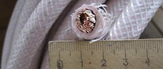
The wire consists of conductors covered with insulated material, in the amount of one or several pieces. To produce high-quality insulation, non-metallic sheaths, windings or braids made of fibrous materials or wire are used. For power lines only, bare wires are typically used.
A cable is a device designed to transmit electricity.
For ease of identification of wires and cables, it was customary to mark them with letters and numbers. This greatly facilitates the work of an electrician, who, with a quick glance at the wiring, will understand what function each conductor performs.
Insulation, armor, protection
The following are used as insulating coatings:
- polyvinyl chloride plastic;
- electrical insulating and silicone rubber;
- cross-linked polyethylene;
- impregnated cable paper;
- polyethylene;
- polytetrafluoroethylene.
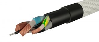
The conductor is protected from mechanical stress by an armor layer that can withstand cuts, vibrations, and compression. This is due to the presence of steel strips in the armor. However, it is not stretch-resistant. Wire armor copes better with the problem of sprains.
The last layer of protection is the outer cover, which is made of cable yarn impregnated with a bitumen composition. This protective device is needed for high-voltage cables. Some manufacturers use polymers to make it.
Protection for low-voltage power cables and wires is made from:
Sometimes such protection is additionally impregnated with a moisture-repellent composition.
Such protection means increase the strength of wires and cables, but greatly affect their cost.
Decoding digital values
Numerical designations follow the letter code. The first number will show how many electrical conductors there are in the cable, and the second will indicate the thickness of these conductors. In the case when the conductors passing through the cable have an equal cross-section, the entry will look like: “2×2.5” - this should be understood as: there are two conductors in the cable, each with a cross-section of 2.5 mm².
However, it often happens that the conductors have different cross-sections; this occurs in three-core cables. In it, the conductor intended for grounding is made thinner than the others. Then the inscription will look like this: “2×2.5+1×1.5”. The entry says that the cable has three cores, two of which have a cross-section of 2.5 mm², and one of which has a cross-section of 1.5 mm².
An example of decoding the marked designation of an ARNBG cable:
After the alphanumeric code, the total footage of the cable section can be displayed (many numbers are indicated and the letter “m” at the end).
Temperature conditions and GOST
This is the final stage of marking, which is applied to wires and cables. This indicator determines the acceptable mode of use (minimum temperatures), then the name of GOST or TU according to which the cable was manufactured is indicated.
However, these designations are often forgotten to indicate, despite the fact that this indicator is very important, especially for regions where very low or high temperatures prevail. Especially when the question concerns the external method of laying wires.
Requirements for inscriptions on tags
Pue-7 clause 2.3.122-2.3.133 laying cable lines in cable structures
Tags on the cable, secured with clamps or threaded through the wire, must be signed in a certain way; this rule is regulated by the rules of the PUE. In accordance with this document, the following data is applied to the label:
- Cable or line number. This is information that contains data about the direction of the highway, what it feeds, and what level of protection is required. During the wiring installation process, an object passport is drawn up, which indicates the buildings or premises powered by this line. They are assigned numbers, which will subsequently be written on the tag itself; during the service process, the technician will be able to look at the markings of the cables and, by comparing them with the object’s passport, understand where this or that line leads;
- Brand and cross-section of wire. Since space on the tag is limited, the designation is written abbreviated, with a minimum number of characters. For example, a vinyl-coated cable with a cross-section of 3*2.5 is briefly designated VVG-3/2.5;
- Line voltage. This is a mandatory parameter, since it is not clear from the outer sheath of the cables what voltage the current flows through it, respectively, and what level of protection is required during repair work;
- The beginning and end of cable lines. For more accurate information about possible losses on the main line after its installation, a designation of the total length is applied. After reading the data, the technician servicing the wire line will be able to accurately calculate the resistance and level of voltage loss in the network.
Labels on tags
All of the information listed is basic and mandatory. It is not prohibited to place additional information on the tag that characterizes the electrical main, for example, the date of laying. In addition, when placing a tag on the coupling, it is necessary to place the date of installation of the wire, since the coupling has its own resource, which will be calculated based on this indicator.
Inscriptions on metal tags are most often made by engraving with a special pencil or indelible paint. Plastic products are signed with a permanent marker or indelible paint. Also, when placing a tag using wire on a highway, it is necessary to additionally protect metal objects with bituminous composition or any other paint, otherwise the wire will rust and collapse, and the tag will be lost. Nylon thread is best suited for fastening; it is not afraid of temperature changes and high humidity.
Tag for threading onto wire
Recently, to indicate the cable on the line, many electricians began to use stickers that already have inscriptions informing about the voltage, as well as empty spaces in which additional data is written. Such stickers are very convenient, since the master does not waste time making markings, but simply glues the element onto the finished tag and continues installation.
What are cable tags made of?
A cable marking tag can have different sizes, which depends, among other things, on the amount of information placed on it. It can be made of various materials, but in any case, care must be taken to ensure that during installation the marking tag does not accidentally damage the wires.
You need to choose a soft material for making tags or make sure that hard marking labels (for example, metal) do not have sharp corners or jagged edges. This will help avoid damage to the insulating sheath of cables and wires.
Today, all marking tags available in the arsenal of electrical installation specialists are divided into three categories:
- classic cable with insert;
- solid plastic;
- made from PVC pipes.
Simple, time-tested and easy to use labels with insert. The necessary information is applied to the thick paper insert, after which it is simply inserted into the grooves on the tag.
The PUE is required to designate each electrical line in accordance with the regulations, regardless of where and in what way it is laid. If the power transmission route has several cable strands, then each of them is marked, indicating the main parameters and direction on the labels.
A tag is attached in front of each circuit breaker containing characteristics such as cable voltage and cross-section. The marking is applied to the labels with a marker that is resistant to external influences, including high temperatures. High-quality labels are not afraid of either corrosion or negative natural factors. They can be used both indoors and for outdoor electrical installations.
When laying the wire in a closed way, in a corrugated sleeve, the step for marking the wires should not exceed 50 meters. The labels are attached using plastic clamps or wire, firmly fixing them in the place selected in accordance with the PUE.
Types of electrical communications devices
The Electrical Installation Rules (ELI) in the “Electrical Wiring” section describe methods for laying cables and wires.
Section PUE 2.1 “Electrical Wiring” specifies the rules for the installation of electrical wiring of power cables, lighting circuits and secondary DC and AC lines in rooms and along the facade of buildings and structures. These are installation wires in a PVC sheath of all sections, unarmored power lines with rubber or plastic coating in a sheath of metal, rubber or plastic. Electrical wiring comes in two types:
- open;
- hidden.
Open
Electric lines are laid on the surface of vertical and horizontal fences, supports and other building structures of buildings and structures. The wires are attached directly to the supporting surface, suspended on cables, rollers and insulators. Communications are hidden in pipes, trays, boxes, metalized shells, baseboards, fillets, etc.
Hidden
Conductors are laid inside the enclosing structures of premises: inside walls, ceilings, ceilings, placed in pipes, boxes or channels covered with plaster.
Important! Marking of cable and wire lines is carried out in open sections of routes. Hidden wiring must be marked under special conditions.
In accordance with the load on different sections of the power lines, the cross-section of the conductors is selected, which will prevent the wires from melting, otherwise this may cause a short circuit and ignition of the electrical wiring.
Why are clauses 1.1.29 and 1.1.30 of PUE 7 incorrect?
What about PUE 7? Paragraphs 1.1.29 and 1.1.30 contain irrelevant and even erroneous requirements for color marking of conductors.
Let's consider clause 1.1.29 of PUE 7:
We see that the requirements of clause 1.1.29 of PUE 7 generally comply with the provisions of GOST R 50462–92, which is no longer in force. And this is no longer correct, since they must comply with the requirements of GOST 33542.
Let's consider clause 1.1.30 of PUE 7:
And the requirements of clause 1.1.30 of PUE 7 contradict the requirements of not only modern GOST 33542–2015, but also all its previous variations - GOST R 50462–2009, GOST R 50462–92 and even GOST 12.2.007.0–75 and, thereby, create conditions for electric shock.
- For example, this paragraph says that you can use separately yellow and separately green colors to color-code phase busbars.
As we already know, GOST R 50462–2009 and GOST 33542–2015 directly prohibited the use of these colors separately in order to comply with electrical safety requirements, since situations could arise when it was possible to confuse protective busbars with yellow-green markings and phase busbars with yellow or green colors.
Clause 6.2.1 from GOST 33542–2015
2) Busbars, which are one of the options for conducting conductors, are usually used in low-voltage switchgear, which are manufactured and certified in accordance with the requirements of national standards, which establish that the color identification of conductors must comply with the requirements of GOST R 50462–92 or GOST R 50462–2009, or GOST 33542.
3) The simultaneous use of blue and cyan colors to identify the pole and middle busbars will inevitably lead to a dangerous situation, since the pole busbar can be under voltage of 110, 220, 440 V or more, and the middle busbar is under voltage almost equal to zero. Moreover, GOST R 50462–92 considered blue and light blue as one color.
4) Phase conductors in the requirements are designated by the letters “ A , B , C ”. However, in IEC standards and national standards developed on their basis, phase conductors are designated differently - “ L1 , L2 , L3 ”.
These and other errors in these paragraphs arose due to the fact that the requirements of clause 1.1.29 of the PUE 7th ed. were formulated on the basis of the requirements of GOST R 50462–92, and the requirements of clause 1.1.30 of the PUE 7th ed. were rewritten from clause 1.1.29 of the PUE 6th ed. sample 1985. That is, errors are rewritten from year to year and no one bothers to correct them.
Main themes
Marking of cable lines (cable tags)
Cable tags
SNIP 3-05-06-85 “Electrical devices”, put into effect on July 1, 1986 (Resolution of the USSR State Construction Committee dated December 11, 1985 N 215)
P. 3.22. Wires and cables laid in boxes and on trays must be marked at the beginning and end of the trays and boxes, as well as at the points where they are connected to electrical equipment, and the cables, in addition, also at route turns and branches. Marking of cable lines P. 3.103. Each cable line must be marked and have its own number or name. P. 3.104. Labels must be installed on exposed cables and cable joints. On cables laid in cable structures, tags must be installed at least every 50 - 70 m, as well as in places where the direction of the route changes, on both sides of passages through interfloor ceilings, walls and partitions, in places where cables enter (exit) into trenches and cable structures. On hidden cables in pipes or blocks, tags should be installed at the end points at the end couplings, in the wells and chambers of the block sewer system, as well as at each connecting coupling. On hidden cables in trenches, tags are installed at the end points and at each coupling. P. 3.105. Tags should be used: in dry rooms - made of plastic, steel or aluminum; in damp rooms, outside buildings and in the ground - made of plastic. Designations on tags for underground cables and cables laid in rooms with a chemically active environment should be made by stamping, punching or burning. For cables laid in other conditions, markings may be applied with indelible paint. P. 3.106. Tags must be secured to the cables with nylon thread or galvanized steel wire with a diameter of 1 - 2 mm, or plastic tape with a button. The place where the tag is attached to the cable with wire and the wire itself in damp rooms, outside buildings and in the ground must be covered with bitumen to protect it from moisture.
Rules for the construction of electrical installations (PUE) clause 2.3.23. Each cable line must have its own number or name. If a cable line consists of several parallel cables, then each of them must have the same number with the addition of the letters A, B, C, etc. Openly laid cables, as well as all cable terminations, must be equipped with tags indicating the brand, voltage, cross-section, number or name of the line on the tags of the cables and terminations; on the coupling tags - coupling numbers and installation dates. Tags must be resistant to environmental influences. On cables laid in cable structures, tags must be located along the length at least every 50 m.
“Rules for technical operation of consumer electrical installations” (PTEEP) 2.4.5. Each CL must have a passport, including the documentation specified in clause 2.4.2. dispatch number or name. Openly laid cables, as well as all cable couplings, must be labeled; the cable tags at the beginning and end of the line must indicate the brand, voltage, cross-section, number or name of the line; on the coupling tags - coupling number, installation date. Tags must be resistant to environmental influences. They should be located along the length of the line every 50 m on openly laid cables, as well as at turns of the route and in places where cables pass through fire-resistant partitions and ceilings (on both sides).
Marking tags are manufactured in accordance with TU 36-1440-82: Round tag (U-135) – intended for power cables above 1000V; Square tag (U-134) – designed for power cables up to 1000V; Triangular tag (U-136) – designed for control cables.
Examples of cable tags:
In accordance with the operating rules for electrical installations, any cable line must have digital and/or letter designations. Often, when an electrical circuit includes several parallel conductors, a combined alphanumeric system is used. In such a situation, the cable tag of each core contains the same numerical value, but different letters of the Cyrillic or Latin alphabet.
The cable sleeve and exposed wires must be marked with tags indicating the number, line name, operating voltage, cross-sectional area and brand of electrical components used. All tags are characterized by resistance to negative environmental factors. The maximum allowable distance between tags is 50 m.
Printing devices and instruments
To apply inscriptions to marking elements, special devices have been developed, which can be divided into several types:
Portable automatic and semi-automatic devices
Canon MK 1500 printer
One of the modern devices for automatic printing on stickers, PVC casings and heat-shrinkable tubes is the Canon MK 1500 printer.
It is possible to select several types of fonts and set cropping modes at different intervals. Printing speed is 2.5 cm per minute, on a 20 mm tube you can print 35 markers per minute with 5 full-size characters.
Hotmarker M-3E
The Hotmarker M-3E printer prints characters on cables, casings and flat tapes using the hot stamping method. The printer's heated dies press the ink into the cable sheath. The matrix has the shape of a wheel, on which there are 10 + space symbols, a total of 7 matrices, this allows you to form thousands of combinations. This printer is capable of marking products with a diameter of 13 mm.
Stationary printers
Brady LabelMark
Used in large-scale production where it is necessary to mark large volumes of products with different types of markers. Brady's software allows LabelMark to quickly change from one program to another. Within 6.5 seconds, it prints characters and sticks a tag on the cable.
The program is placed on a regular PC and transferred from it to the printer. To operate the program and operate the printer, no special highly qualified training is required. The device has a high print resolution, up to 300dpi, which allows you to print small fonts and clear images of logos. Symbols are applied to wires with diameters of 1.5-15.2 mm, maximum marker dimensions 50.8 X 50.8 mm.
| Specifications | ||
| Printing technology | thermal transfer | |
| Print Resolution | 300 dpi (300 dpi) | |
| Production cycle duration, seconds | 4,5 — 6,5 | |
| Minimum wire diameter, mm | 1,52 | |
| Maximum wire diameter, mm | 15,24 | |
| Maximum print width, mm | 50,8 | |
| Maximum print length, mm | 41,3 | |
| Maximum label width, mm | 50,8 | |
| Maximum label length, mm | 76,2 | |
| Minimum label width, mm | 6,35 | |
| Minimum label length, mm | 19,05 | |
| Ribbon outer diameter | 68.58 mm | |
| Fonts, Barcodes, Graphics | Printing fonts, barcodes and graphics are consistent with LabelMark™'s label creation capabilities . For more information on this issue, check out LabelMark™ software. | |
| Interfaces and connectors | USB, Serial RS-232C, Ethernet, PCMCIA, CompactFlash | |
| Memory | Built-in 4Mb Memory expansion 32Mb RAM using PCMCIA or CompactFlash® | |
| Dimensions, mm | 571.5 x 368.3 x 450.9 | |
| Weight, kg | 38,5 | |
| Operating temperature | from 10° to 41° C | |
| Storage and transportation temperature | -18° to 60° C | |
| Humidity | from 20% to 80% without condensation | |
| Nutrition | 90-264 V AC, at 47-63 kHz | |
Office laser printers
Used when printing on sheets of self-adhesive stickers or regular sheets of A4 paper. Tags are placed on the cables and wrapped with transparent tape. This is a simple and cheap way for small volumes of marking.
Tip #1. Do not buy expensive marking equipment if you are not professionally involved in electrical installation work. Use low cost labeling methods.
Rules for placing tags on devices
What is PvS wire, its decoding, technical features and varieties
When installing in closed channels or collectors, the tags must be located in inspection wells, regardless of their distance from each other. The part is attached on both sides of the collector to each of the route branches. It is also necessary to mark the turning sections of the line on both sides, indicating the direction of rotation and degree.
When wiring passes through ceilings indoors or under the road surface, an inspection box must be installed, and the wires are marked with plastic tags.
When laying electric lines through undeveloped territory or lands intended for agriculture, markings are installed along the entire route in the form of poles with tags, which are also marked with the characteristics of the power line. Such poles will act as an object for reference to the terrain, their coordinates are included in the route plan, and if necessary, it will be possible to accurately determine the location of the cable under the ground.
Thus, according to the rules and regulations, all power installations and cable lines are subject to mandatory labeling, regardless of their voltage type and location. In addition, any qualified craftsman will agree to carry out repair work in an emergency area only if he has sufficient information about the characteristics of the electrical line.
What color of electrical tape do electricians use?
Experts use colored electrical tape to mark the wires. This is a familiar, convenient and simple way. Moreover, electrical tape is inexpensive and is always at hand. It can not only insulate, but also mark wires.
- White is the most convenient color for marking; you can sign if necessary. Easy to find among the wires - stands out due to its color. · Black - used to insulate current-carrying conductors. Experts prefer the rag version; its properties are superior to conventional PVC and more reliably protects against mechanical damage.·
- Blue is an ideal option for insulating neutral conductors. Usually it is not wound around the connection, but only a couple of turns are made to make the wire visible in the junction box.
- Red - this color is most convenient to designate phase wires. For example, when the neutral wire is insulated in blue, the phase wire should be different.
- Yellow, as well as yellow-green, helps to identify buses and grounding wires located in protective networks.
The blue tint is working zero, red is phase, yellowish-green is ground.
Requirements for types and methods of attaching tags
In addition to the placement of tags, all information about the markings produced on cable lines and communication devices is recorded in a special journal. Such records are regularly updated depending on changes that have occurred in the network structure.
Ley Line Markers
In accordance with GOST, plastic plaques are made in square, round or triangular shapes. They are used in open areas of cable routes and circuit components. The tags have two holes through which the wire or core should be threaded, after which it is securely clamped and fixed in the desired position.
For lines whose voltage does not exceed 1000 V, square tags are used. If the operating voltage is above 1000 V, then round plastic plaques are used. Triangular products are required for control power lines.
Tags for low power circuits
For such purposes, small plates made of polymer materials can be used, which indicate information about the electricity consumption of the circuit subscriber and other data.
Main types of cable markers
A marking tag in accordance with international standards must be installed on open cable routes and power installations. If the wire is laid in structures specially designed for this purpose, then the distance between the markers can be 50-70 m. You cannot do without them in a number of other cases:
- when the route crosses various obstacles that make visual inspection difficult (interfloor ceilings, walls, partitions), then tags are placed on each side of the obstacle passed (for example, on both sides of the wall);
- at points where the direction of the cable line changes;
- in places where input or output from other structures is carried out.
Many manufacturers and electricians prefer cable tags made of plastic, since such material can withstand moisture for a long time without changing its properties.
Form of marking tags
The rules and regulations indicate information on the forms of tags, which were described above:
- triangular - installed in cable lines for control or signaling purposes;
- square – for power lines with voltage up to 1 kV;
- round – over 1 kV.
Label sizes
The most common brands of cable tags are U-134, U-135, U-136 and U-153. Let's compare their sizes and, depending on the data obtained, draw conclusions on possible use in systems:
- U-134 is used to mark power lines with voltages not exceeding 1000 V. The square tag with an area of 55x55 mm is equipped with two 11x3.5 mm grooves for fixing with a cable binder.
- U-135 is suitable for indicating information on electrical circuits with voltages over 1000 V. Round products with a diameter of 55 mm and similar grooves for cable binders.
- U-136 is used for marking signal and control wires. The triangular product has equal sides 62 mm long each. There are two slots for a cable binder of the same size.
- U-153 is used for power lines with voltages up to 1000 V. A square product with a length of 28 mm and a 5 mm hole is attached using a special wire.
Important! Many organizations either ignore the cable tagging process or perform it using free-form tags. The consequences of both decisions can cause frequent emergencies and injury to operating personnel.
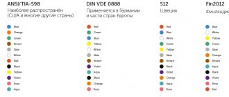
Color coding of wires and cables
Generally accepted standards and rules for color marking the insulating sheath of wires allow you to quickly and accurately determine the operating parameters of a cable and understand in which systems and devices it can be used. The color marking regulations are prescribed by PUE and GOST.
It is noteworthy that the designation system will be different for cable networks with alternating current or direct current. Often the cable is made in different colors. Instead of a shell, color marking can be done using heat-shrinkable tubes (cambrics). Another option is colored electrical tape. The choice of color for phase and neutral wires should always be different!
For three-phase alternating power lines, the buses should be marked as follows:
- first phase – yellow;
- the second is green;
- the third is red.
In DC cable runs, color designations are chosen according to the charge, which can be positive or negative. In the first case, a wire with a red braid is selected, in the second, a wire with a blue braid. The system does not support phase and neutral wires, and for the middle wire a light blue conductor is usually used.
For power installations with voltage up to 1 kV and neutral, the following marking is carried out:
- working neutral wire – blue;
- grounding – yellow-green;
- combined zero – yellow-green with blue markers (or blue with yellow-green markers);
- phases - red, black and other colors depending on the quantity.
It is noteworthy that the wiring inside electrical appliances is red, in sockets - brown.
The order of placement of conductors
When wiring multi-core lines proceed as follows. Wires are grouped into bundles, dividing them according to their intended purpose. A bundle of phase conductors is formed, neutral wires and grounding are assembled separately. If possible, the bundles are formed in even rows without interlacing. This will make it easier to find a particular wire.
In some cases, the phase and neutral wires that supply a specific consumer are placed in one bundle. Corresponding badges are attached to all bundles.
Cables in a switchboard or communication center are marked with tags to make it easy to find the desired line and determine its parameters.
Panel marking
Photos of cable markings
- Wire connector: instructions on how to make the connection yourself. Instructions for use of clamp, clamp and lugs
- Wire lugs: instructions on how to select and install a lug. Overview of all types, photos, instructions, diagrams
Heat shrink for wires: all types and characteristics. Detailed description of how to choose and use heat shrink
Read here! Wiring in an apartment: rules for planning the electrical network, installation of the system and features of cable laying (85 photos)
Alphanumeric marking structure
Marking of wires and cables allows you to quickly find the desired wire among similar products that have the same type and color.
At large industrial facilities, where the number of installed communications is in the thousands, tags are used.
An experienced installer just needs to look at the markings and find out the size of the cross-section of the cores; cross-sectional area, which ranges from 0.35 to 70 square meters. mm; the number of cores and the metal from which they are made.
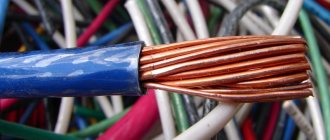
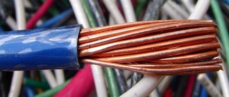
SIP wires are made from aluminum billets. The VVG cable, according to the marking, is made of copper wire.
Scheme of alphanumeric marking of power cables and wires
The cable marking contains information about the rated voltage for which the product is designed. The marking also contains information about the insulating material.
According to GOST, the list of such materials is strictly limited. Among the most well-known are rubber, paper, PVC and other plastics.
And one more important parameter that is important when choosing a cable is the material of the protective sheath. The outer shell is made of metal, plastic, rubber.
Tags with information about the purpose of the product are attached during the installation process. Deciphering the cable markings is inherently simple.
The initial letter in the marking code characterizes the metal from which the core is made. For aluminum conductors, the letter “A” is used. There are no letters for copper.
The same materials are used here, vinyl and rubber.
The fourth letter characterizes the cable design. “A” indicates that the cable is covered with an asphalt coating. "B" - armored with metal. “G” - has no protective cover or, as installers say, naked.
What else is important to know
The photo below shows the board in which the wires were marked during installation:
When assembling an electrical panel, electrical wiring groups should be marked as follows: the input wire is marked as L, and the output wire is marked Gr (indicates that these are groups). After the letter the group number and line number are indicated.
Also, during marking, it is important to take into account all color differences so that an emergency situation does not arise. If, after opening the cabinet, no markings were found, then you need to use a probe to determine where each wire is located.
We talked about how to use an indicator screwdriver to determine phase and zero in the corresponding article. Since this will take a lot of time, it is better to leave marks when checking so that another electrician who will carry out repairs or maintenance can understand where which wire is.
If there are no conductors of the required color, then you can use any color, as long as the ends of the cores are correctly marked during installation. This can be done using colored electrical tape or special heat-shrinkable tubes.
Heat shrink markings look like this:
This is the technology used to mark wires and cables when installing an electrical panel
As you can see, marking the lines is very important, and the process itself does not take much time
Please note that with the help of these instructions you can mark conductors not only in power electrical panels, but also in automation panels (for example, to mark signal cables and control)
It will be useful to read:
Alphanumeric designations
GOST specifies regulations for marking the external insulation of cable lines, thanks to which cords, cables and wires can be distinguished from each other. If there are no markings on the braid or they are not sufficient for maintenance and safety, then special tags with additional data are attached to the route.
According to the rules and recommendations prescribed in GOST, a wire is a product consisting of one or more cores, which are protected with insulation along their entire length. The cores can be produced without insulation. A cable is defined as several conductors insulated separately from each other, placed under a single sealed sheath made of metal or polymer materials. A cord consists of two or more flexible conductors that are connected together by twisting or braiding. The cores are fixed along their entire length, and the braid is made from non-metallic materials.
All cables are divided into several groups:
- power;
- signaling and control;
- installation;
- radio frequency;
- connected.
You can decipher the alphanumeric symbols on the insulation yourself.
The first letter in the abbreviation indicates the material the core is made of. The letter “A” at the beginning indicates that the current-carrying conductor is made of aluminum. The absence of such a letter means that it is made of copper.
The second letter indicates the scope of application of the product. If the second letter in the abbreviation is missing, then such a cable is considered to be power.
The third letter is used to indicate the degree of flexibility of the product. Its absence indicates a single-core wire, the presence of the letter “G” indicates a flexible multi-core wire.
The fourth letter allows you to designate the material used to make the insulation. Windings are made from different materials, so more specific designations are used for it.
The fifth letter indicates the material used to make the outer shell and the presence or absence of an armored hull.
The sixth letter can be used to indicate the protective cover, the purpose of the layer and the structure as a whole.
What else is important to know
The photo below shows the board in which the wires were marked during installation:
When assembling an electrical panel, electrical wiring groups should be marked as follows: the input wire is marked as L, and the output wire is marked Gr (indicates that these are groups). After the letter the group number and line number are indicated.
Also, during marking, it is important to take into account all color differences so that an emergency situation does not arise. If, after opening the cabinet, no markings were found, then you need to use a probe to determine where each wire is located.
We talked about how to use an indicator screwdriver to determine phase and zero in the corresponding article. Since this will take a lot of time, it is better to leave marks when checking so that another electrician who will carry out repairs or maintenance can understand where which wire is.
If there are no conductors of the required color, then you can use any color, as long as the ends of the cores are correctly marked during installation. This can be done using colored electrical tape or special heat-shrinkable tubes.
Heat shrink markings look like this:
This is the technology used to mark wires and cables when installing an electrical panel
As you can see, marking the lines is very important, and the process itself does not take much time
Please note that with the help of these instructions you can mark conductors not only in power electrical panels, but also in automation panels (for example, to mark signal cables and control)
It will be useful to read:
Common labeling mistakes
Let's list three main mistakes:
- The most common one is caused by novice electricians or experienced specialists due to inattention. In the process of screwing the wire to the shield and terminals, the craftsmen simply forget to put a heat-shrinkable tube with markings (tube) on the wires. Because of this, you have to unscrew the attached wiring and put the products on again.
- Often craftsmen confuse the PEN conductor with a grounding cable. The fact is that both elements have identical color markings, so you need to inspect them more carefully.
- If the panel is located outside the site, then it is necessary to conclude an agreement with the electrical energy supplier. You must have on hand technical documentation with a diagram and confirmation of compliance with the requirements of the PUE, PTEEP and other regulatory acts. Otherwise, you may face claims from Rostekhnadzor.
Qualified specialists will agree to carry out repair work and engage in maintenance of emergency areas only if sufficient information about the parameters of the line is provided. This is exactly what is contained on the cable tags.
To properly install and operate electrical wiring and other devices, you must have at least minimal knowledge of the standards for cable lines and electrical installations. There are many provisions and instructions governing the actions of an electrician and installer when working on electrical lines of various voltages. Such documents also include the Rules for marking wires on the main line and in the distribution cabinet. This article discusses the types of tags for cable markings, as well as the conditions under which the label should be on the surface of the wire.
Cable tags
Important connection points in the shield
The panel with all the correct markings for wires and cables looks like this:
Each group of electrical wiring must also be designated according to a certain principle:
- The letter "L" indicates the input wires.
- The letters "Gr" indicate groups.
- After the letters, numbers indicate the numbers of lines and groups.
Don't forget about color codes, since mixed up colors often cause accidents. Sometimes, when opening a cabinet, you may not find any markings; in this case, you need to use probes to understand which wires serve which purposes.
A screwdriver with an indicator will help you determine the purpose of the wires, with which you can easily find zero and phase. During the verification process, it is necessary to leave markings so as not to confuse the assignments of the conductors in the future.
It happens that you have to install conductors with markings of the wrong color that is required. In this case, remember about other markings on the ends of cables and wires; they must always be correct.
Insulating tape can also help make markings, but it is better to use the materials we wrote about above.
Heat-shrinkable tubes, which can also be used for marking, look like this:
Marking must be carried out not only in the panels, but also in the automatic control panels. This is necessary to distinguish different conductors, for example, to immediately identify signal cables and other conductors.
This is the basic information you need to know when marking conductors. Do not ignore the markings and follow the rules that we described in the article!
Marking with color and other symbols will help not only simplify repair work and maintenance, but also save human life and health during electrical installation work. In addition, the marking process does not take much time.
How to mark
The most reliable method of marking cable lines is stamping. On the other hand, this method requires the presence of special equipment (a printer), which cannot always be used.
In many ways, the choice of a specific method depends on the material used to make the cable tag. You can also buy markers with already prepared symbols, sold in ribbons. They have cuts that allow you to quickly and accurately remove the desired label and fix it on the wire using an adhesive surface.
The inscriptions are made from waterproof paint or ink. If the electrical circuit is installed in rooms with high humidity levels or is constantly exposed to an aggressive environment, then the marking is applied by milling, punching, burning or stamping on plastic/metal.
For dry rooms with good ventilation or air conditioning, you can get by with marking using standard means - a pencil or felt-tip pen.
Non-standardized wire designation options
But unfortunately, the marking of the wires is phase zero; grounding is not always carried out in accordance with the PUE standards. You can often find other designations. This especially often applies to old circuits, electrical equipment, as well as some new devices from non-certified manufacturers.
And so that they do not mislead you, let's look at the most common options.
- Quite often on old Soviet diagrams you can find the symbols “F” or “F1”, “F2” and “F3”. The decoding of this designation is quite simple - it means phase. Moreover, a symbol without a letter designation is used for a single-phase network, and with a letter designation for a three-phase network.
- On the new diagrams you can find the designation “L” or, respectively, “L1”, “L2” and “L3”. This is how foreign manufacturers often designate a phase. As for digital designations, the same rule applies here - without a number for a single-phase network, with numbers for a three-phase network.
Note! For a single-phase network, the designation “F” or “L” does not indicate the importance of strictly observing the phases. That is, you can connect any phase. The same applies to a three-phase network with a digital designation. If there is a designation “Fa”, “Fv”, “Fs” or “La”, “Lv”, “Lc”, then compliance with the phase sequence is mandatory.
- The marking of wires in switchboards may contain the symbol “0” . This designation of the neutral wire is often used to this day both in diagrams and in the designation of terminals on equipment.
Example of non-standard designation on diagrams
- To designate a protective conductor, the grounding symbol is often used, which we already discussed above . It is usually used to indicate the connection point of the protective conductor made using a system other than TN-CS.
- DC panel wire markings may contain the symbols “L+” and “L―”. These symbols indicate positive and negative conductors, respectively, and should not mislead you.
Types of tags
Branding of wires is carried out using factory-made or self-made tags. But their form must strictly comply within certain standards.
These standards determine the types of labels used to mark cable lines. The following forms of these products exist:
Square
. They designate power lines up to 1000 V. As a rule, these are lines for household use.
Round
. They are used to show wires through which voltages exceeding 1000 V are supplied. Such lines are classified as industrial, which require a high degree of safety during installation and use.
Triangular
. They are used to mark low-voltage wires. It is made in the shape of an equilateral triangle.
Marking of cables and wires
Cables are always marked with letters and numbers. They can indicate the properties of the product, its length, cross-sectional area and other parameters. Below are three main types of cable product markings.
Digital designation
The numbers on the product mainly contain data on the cross-sectional area, permissible voltage for the wire, and length of the product. Sometimes the number of cores is written on the marking. For example, VVG 2×1.5, which can be deciphered as a power cable with two cores and an area of 1.5 mm square for each of them. Suitable for voltage 1 kilowatt.
Letter designation
Letter designation of the brand
All properties of the product are written in letters. The wire can be double-sheathed, shielded, bare, grounded or non-flammable. For example, you can take VVGng, which means that this is a power wire, with two layers of insulation, resistant to fire.
Color coding
The color coding mainly indicates the phases of the wires. This helps avoid confusion during the process of laying the line. Primary colors, yellow, green, red and blue. For the zero phase and grounding, dark yellow or blue shades are used.
How are the wires designated?
Wires, unlike cables, have a smaller cross-sectional size. They come with protection and are not insulated, single- or multi-core.
The first way to distinguish them from a cable is to see the “P” (wire). The letter will appear at the beginning if it contains copper conductors (in this case the designation is not placed). The second one will be when the cores are made of aluminum, marked “A”:
- PBPPG - wire (P), for use in everyday life and at work (BP), flat in shape (P), flexible (G).
- APPV - wires made of aluminum (A), flat in shape (PP), in PVC protection.
Wires come in round and flat sections. The round one is not displayed in any way, and the flat one is indicated by the letter “P”.
Mounting wires used in electronics manufacturing are designated "M". For example, MGShV is an installation, multi-core conductor protected from polyamide and PVC.
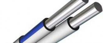
If an overhead connection method is used, self-supporting wires are used. These structures do not require support; they have a sufficient level of rigidity and support their own weight. These are SIP wires:
- SIP-1: self-supporting, neutral is not insulated;
- SIP-2: the same, but with an insulated neutral;
- SIP-4: cores with protection and the same cross-section.
Also present in cable and wire products is a special group – heating wires. For their marking, after the designation “P”, “N” is indicated, indicating the application.
- PNSV - wire (P),
- For heating (H),
- Lived of steel
- Single, PVC protection.
Insulation type, armor and protection
The decoding of the cable abbreviation should be carried out taking into account generally accepted standards.
Core material
There are only 2 options here:
- absence of a letter - copper (copper wire does not need any designation);
- “A” is a letter designating conductors made of aluminum.
The data from this table will help you decipher abbreviations and abbreviations.
| Letter designation of insulation material (2nd position) | |
| IN | This type of insulation is made of polyvinyl chloride (in other words, PVC). |
| P | Polyethylene was used in the manufacture of insulation. |
| R | Rubber is used for insulation. |
| HP | Nairite (non-flammable rubber) |
| C | Film insulation (used in the manufacture of installation wires) |
| G | The protective layer is completely absent (bare). |
| F | Fluoroplastic |
| TO | This letter designates the control cable (its purpose). |
| KG | Flexible cable |
| Letter designation of the protective shell, if present (3rd position) | |
| A | Made of aluminum. |
| P | Protective sheath - polyethylene hose |
| Pu | Reinforced polyethylene hose |
| WITH | Lead sheath |
| R | Made from rubber |
| IN | PVC (polyvinyl chloride) sheath |
| Letter designations of the material for the manufacture of the type of armor, if any (4th position) | |
| BbG | The armor consists of a profiled tape made of steel. |
| Bn | The armor consists of steel strips equipped with a protective cover; the material does not support combustion. |
| IN | Polyvinyl chloride used |
| Bl | Armor made of steel tapes, Bl |
| D | The braid is made of double wire. |
| TO | Round steel wires, which are enclosed in a steel cover, are used as armor. |
| P | Flat steel wire armor |
| D | A braid consisting of two wires is used. |
| Type of outer cable cover used (5th position) | |
| E | Screened cover (often this type is represented by aluminum foil) |
| G | There is waterproofing (protects against corrosion) |
| IN | This letter designation can have 2 decodings. If it is in the middle, the protective sheath is made of PVC, the second variety is the placement of “B” at the end. This means that the cover is made of paper. |
| ABOUT | Wires covered with insulation and connected using a winding |
| N | Cover made of non-flammable material |
| Shp | Protection is provided by a polyethylene hose. |
| Shv | Vinyl hose |
| Shps | Self-extinguishing polyethylene |
- MK - means main cable;
- Ш - mine;
- MK - these letters are applied to the main cables;
- RK - abbreviation indicates radio frequency cable;
- T - intended for telephone communication;
- O - optical type;
- KS - cable products for communication;
- KM - characterizes the combined main view;
- VK - these letters characterize intrazone communication cables;
- PPP - insulation is presented in the form of a three-layer film (film-pores-film).
- Z - in this type of cable, the cores are twisted into a “star” four.