To understand for what operating conditions a particular current or voltage transformer, as well as other types, is intended, special markings of devices are used. Domestic and imported units have different designations. In our country, installations manufactured in accordance with GOST are more often used.
Transformers are marked on a metal shield on the housing. The most common types of transformer symbols will be discussed below.
Main characteristics of the transformer
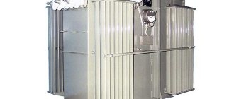
Figure 1.3 shows the appearance of the transformer TRDN-40000/110.
Figure 1.3 – Appearance of transformer TRDN-40000/110
In accordance with the accepted notation system, the abbreviation of the transformer TRDN-40000/110-U1 is deciphered as follows: T - three-phase transformer; P - the presence of a split low voltage winding; D - cooling is carried out with natural circulation of oil and forced air circulation; N - voltage regulation is carried out under load on-load tap-changer; 40000 – rated power of the transformer, kV•A; 110 – voltage class of the high-voltage winding, kV; U1 – climatic version, placement category according to GOST 15150. The main parameters of this transformer are given in Table 1.1 [].
Table 1.1 – Technical parameters of TRDN-40000/110-U1
| Rated frequency, Hz | 50 |
| Winding connection diagram and group | Υн/Δ-Δ-11-11 |
| Rated value of HV voltage, kV | 115 |
| Rated value of LV voltage, kV | 11 |
| Short-circuit voltage (HV-LV), % | 10,5 |
| No-load current, no more, % | 0,55 |
| On-load tap-changer control stages in the HV neutral | ±9x1.78% |
| Full service life, years | 25 |
The requirements for power transformers state that to ensure long-term and reliable operation of transformers it is necessary to ensure:
- compliance with the required load, temperature conditions and voltage levels;
- compliance with the characteristics of transformer oil and insulation within the established standards;
- maintaining transformer cooling devices, oil protection, voltage regulation, etc. in good condition.
Links and literature
How to decipher tire markings
. Rozhkova L.D., Kozulin V.S. Electrical equipment of stations and substations. - M.: Energoatomizdat, 1987. - 315 pp. Neklepaev B.N. Electrical part of power plants and substations. Textbook for universities. 2nd ed. - M.: Energoatomizdat, 1986.-310 pp. Rules for the technical operation of electrical installations. Approved by order of the Ministry of Fuel and Energy of Ukraine dated July 25, 2006. GOST R 52719–2007. Power transformers. General technical conditions. – M.: Standards Publishing House, 2007. – 45 pp. GOST 12.2.007.0–75. System of occupational safety standards. Electrical publication. General safety requirements. – M.: Standards Publishing House, 1975. – 12 p.. GOST 12.2.007.2–75. System of occupational safety standards. Power transformers and electrical reactors. Safety requirements. – M.: Standards Publishing House, 1975. – 5 p.
Varieties
The designation of transformers necessarily begins with the type of equipment. If the marking begins with the letter A, it is an autotransformer. Its absence indicates that the unit belongs to the class of power transformers.
The number of phases is required. This allows you to choose an installation operating from a household or industrial network. If the transformer is connected to a three-phase network, the marking will contain a T. Single-phase varieties have the letter O. They are used in household networks.
If the device has a split winding, it will have a P. If there is on-load voltage regulation (OLTC), the device will be marked H on the metal plate. If it is absent, we can conclude that the presented feature is absent in the device.
Purpose
After the category of performance features, information about the purpose and scope of the equipment is presented. Marking with the letter B indicates the ability of the structure to warm up the soil or concrete in winter. A transformer intended for drilling rigs may have the same designation.
When electrifying the railway, installations with special properties and characteristics are needed. They are marked with the letter Z. Devices with the designation M are used at metallurgical plants.
When transmitting direct current through a line, class P structures are needed. Units for ensuring the operation of submersible pumps are designated as PN.
If the unit is used for the power plant’s own needs, it belongs to category C. Type TO is used for processing soil and concrete at high temperatures, providing electricity for temporary lighting and hand tools.
In coal mines transformers of the Sh variety are used, and in the electrical power supply system of an excavator - E.
Scheme
All data shown on the plate can be divided into 6 groups. In order not to get confused in the information, you should consider the sequence of its writing. For example, installation ATDTsTN-125000/220/110/10-U 1. The following groups are used to mark the features of the device:
- Group I. A - Designed to indicate the type of device (power or autotransformer).
- Group II. T - Corresponds to the type of network for which the device is used (single-phase, three-phase).
- III group. DC – Cooling system with forced circulation of oil and air.
- IV group. T – Shows the number of windings (three-winding).
- V group. N – Voltage is regulated under load.
- VI group. All numbers (rated power, voltage of HV MV windings, climatic version, placement category).
You should learn more about each category. This will make the choice much easier.
Last changes
14.09.2018
A new person who has the right to act without a power of attorney: Director Igor Nikolaevich Travichev
Lylov Sergey Fedorovich is no longer a person entitled to act without a power of attorney
19.11.2016
The address of the organization is excluded from the register of the Federal Tax Service Addresses indicated during state registration as the location of several legal entities
23.10.2016
The address of the organization is included in the register of the Federal Tax Service Addresses indicated during state registration as the location of several legal entities
18.08.2016
New license No. LO-33-01-002188 dated July 15, 2016, type of activity: Medical activities (with the exception of the specified activities carried out by medical organizations and other organizations included in the private healthcare system in the territory of the innovative)
Information about license No. LO-33-01-001245 dated 05/03/2013, type of activity: Medical activity (with the exception of the specified activities carried out by medical organizations and other organizations included in the private healthcare system in the territory of the innovative) has been removed.
01.08.2016
The organization is included in the Register of Small and Medium Enterprises, category: small enterprise
22.07.2016
New license No. LO-33-01-001245 dated 04/22/2013, type of activity: Medical activities (except for the specified activities carried out by medical organizations and other organizations included in the private healthcare system in the territory of the innovative one)
Information on the case
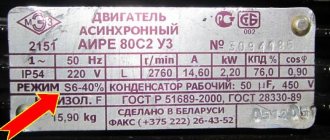
The information presented on the visible side of the device is applied using engraving, etching or embossing. This ensures the clarity and durability of the inscription. The metal plate contains information about the equipment manufacturer. The year of its manufacture and serial number are applied.
In addition to information about the manufacturer, there must be information about the unit. The number of the standard to which the presented design corresponds is indicated. The rated power indicator must be indicated. For three-phase devices, this parameter is given for each winding separately. Information about the voltage of the coil turns branches is indicated.
The rated current is determined for all windings. The number of installation phases and current frequency are given. The manufacturer provides data on the configuration and connection groups of the coils.
After the above information, you can familiarize yourself with the short circuit voltage parameters. Installation requirements are provided. It can be external or internal.
Technical characteristics allow you to determine the cooling method, the mass of oil in the tank (if this system is used), as well as the mass of the active part. The switch actuator indicates its position. If the installation has a dry type of cooling, there is data on the power of the installation when the fan is turned off.
The serial number must be stamped under the shield. It is present on the tank. The number is indicated on the cover near the HV input, as well as on the top and left on the core beam flange.
Numbers
The listed designations may be followed by numerical values. This is the rated winding voltage in kV, power in kVA. For autotransformers, information about the voltage of the MV winding is added.
The marking may contain the first year of manufacture of the presented design. The power of the units can be 20.40, 63, 160, 630, 1600 kVA, etc. This indicator is selected in accordance with the operating conditions. Higher power equipment is available. This parameter can reach 200, 500 MVA.
The duration of use of Soviet-made transformers is about 50 years. Therefore, modern energy communications can use equipment manufactured before 1968. They are periodically improved and reconstructed during major overhauls.
Special designations
Depending on the installation category, special symbols may apply. For a current and voltage transformer, they may not be the same. The second type of technique is used when operating protective mechanisms or for measuring current. The first category of devices is intended to change the value of alternating current.
Voltage transformers do not use high power transmission of electricity. They are capable of creating isolation from low-voltage communications. This category of devices is used in circuits with a voltage of 12V or less. Their main operating parameters are the current and voltage of the primary winding. It is their value that is provided by the manufacturer.
The marking of voltage transformers begins with their design. If this is a walk-through structure, it is designated by the letter P. If it is not there, this is a supporting type of apparatus. The cast insulator is marked L, and the porcelain insulator is marked F. The built-in insulator is marked V.
Decoding of modern current transformers is carried out in the established sequence. It begins with T, which characterizes the devices presented. The installation method can be through-type (P), support (O) or busbar (W). If this device is present in the equipment of power transformers, it is designated as VT. If it is built into the oil switch, then the marking will have the letter B. When installed externally, the device will have an H.
Safety requirements and environmental protection
How to decipher the markings of cables and wires?
General technical conditions for power transformers are given in []. GOST includes technical requirements, safety requirements, including fire safety requirements, environmental protection requirements, operating instructions, transportation and storage. Safety requirements must also comply. According to the standard [], grounding of transformer tanks is carried out.
The degree of protection of transformers is determined by the standard []. It states that all transformers, except built-in ones, must be made with protection class 1 or 2 and have a degree of protection of at least IP20. Stationary transformers, in turn, can be manufactured with a degree of protection IP00. The system of standards [] provides requirements for transformer disposal. It describes the following series of actions:
- transformer oil should be drained and sent for regeneration;
- metal components of the transformer must be recycled;
- porcelain insulators, electrical cardboard, rubber seals must be sent to a solid waste landfill.
Dry systems
One of the new varieties is dry cooling systems. They are easy to operate and maintain, not demanding and not capricious. If the installation is open and air circulation occurs naturally, it is marked as C.
The protected version is designated by the letters SZ. The housing can be closed from the influence of various environmental factors; it is called hermetically sealed. With natural air circulation in it, the marking has the letters SG.
Air cooling systems may have forced circulation. In this case, the device is designated by the letters SD.
Execution
Installations may differ from each other in their design features. If they have forced water circulation, the letter B on the body will make it clear. If there is protection against thunderstorms and lightning, the design is marked G.
The system may have natural circulation of oil or non-flammable dielectric. At the same time, in some varieties protection with a nitrogen cushion is used. It does not have expanders or leads in the flanges of the tank walls. The designation has the letter Z.
Cast insulation is designated as L. The suspended version is designated by the letter P. The improved category of devices is designated as U. They may have automatic on-load tap-changers.
Equipment with leads and an expander installed on the flanges of the tank walls is marked with the letter F. An energy-saving device has reduced energy losses at idle. It is designated by the letter E.
How to decrypt data
Transformers are designated in the form of a set of letters and numbers of the form XXXXXXX – 1234 / 1234 – X1, where instead of the letter “X” a certain letter is placed, which in order shows the type, number of phases, how many low voltage windings, cooling system and special designations for special types transformers.
Not all letters will always be present in the designation of a transformer; their presence in the marking depends only on the presence of these characteristics.
The digital designations contain the main characteristics of the transformers: rated power, rated voltage class of the HV winding, and the last two digits indicate the year of production.
Type
If the letter “A” appears at the beginning of the symbol, then this is an autotransformer. If it is missing, then the power transformer is a step-up or step-down transformer.
Number of phases
To indicate the number of phases, the letters “T” - three-phase and “O” - single-phase are used.
Split winding
After this letter there is information about the split winding - “P”. This means that there are two or three windings at the step-down voltage.
Heat dissipation
The cooling system is designated by the following letters:
- C – dry transformer, that is, air cooling;
- SZ - the same, but in a protected version;
- SG – sealed air-cooled;
- SD – air cooling using a fan;
- M – oil cooling with natural circulation;
- D – the oil tank is cooled using a fan (blown);
- C – forced oil circulation;
- DC is a combination of two cooling methods: blowing and circulation.
Number of windings
After the cooling system there may be a letter “T”, which indicates a three-winding transformer. Interestingly, the two-winding type does not have a symbol.
Voltage adjustment under load
In the case when the number of turns on the transformer can be changed without disconnecting the electrical circuit, then in this case this means that voltage regulation can occur under load and is marked with the letter “H”. When adjusting with switching off - switching without excitation - the letter is missing.
Execution
There are devices with special design solutions. Suspended transformers are designated by the letter “P”, with cast insulation – “L”, energy-saving transformers are designated by the letter “E”, and improved ones – by the letter “U”.
Purpose
Depending on the scope of application, at the end of the marking there may be a letter giving information about this. For work at the power plant itself - “C”, when used on railways - “F”, at metallurgical enterprises - “M”.
TCM transcript
These electromagnetic devices are designed for three-phase circuits and are made without additional cooling, that is, dry. Their power ranges from 0.16 to 1 kVA, most often used for rectifiers and semiconductor power supplies. One of the advantages of such a device is that it can be located in the housing in any position, horizontal or vertical.
The decoding of its markings is as follows:
After which its power and additional conditions of climatic use are indicated.
In industry and in everyday life, many dry and oil-based transformers for various purposes are used. If there is a factory plate on them, then deciphering it is not difficult. The main thing is to apply it in accordance with the type of electrical installation, power, and also that the voltages and currents of all windings are used under normal conditions without overloads. Then these unpretentious, reliable and low-maintenance devices can last for decades.
Special designations
There are separate categories of transformers for which different designations are used. In particular, these are current and voltage transformers. The type is immediately indicated at the beginning of the letter code: “T” for the first type and “N” for the second. The following is information about the installation method: “P” for walk-through, “O” for support and “W” for busbar. Insulation is also designated by special letters: “L” for cast insulation, “F” for porcelain insulation and “B” for built-in insulator.
Examples
To understand how to interpret the information on the equipment body, you should consider several examples of markings. These can be the following transformers:
- TDTN-1600/110. Three-phase class of step-down type equipment. It has oil forced cooling and an on-load tap-changer. The rated power is 1600, and the HV winding voltage is 110 kV.
- ATDTsTN-120000/500/110-85. Autotransformer, which is used in a three-phase network. It has three windings. The oil cooling system has forced circulation. There is an on-load tap-changer. The rated power is 120 MVA. The device reduces voltage and operates between 500 and 110 kV networks. Developed in 1985.
- TM-100/10 is a two-winding unit that is designed to operate in a three-phase network. The oil circulation system has natural fluid movement. The voltage change occurs using the PBB unit. The rated power is 100 kVA, and the winding class is 10 kV.
- TRDNS-25000/35-80. Device for a three-phase network with two split windings. Cooling is carried out through forced oil circulation. The design includes an on-load tap-changer regulator. Used for the needs of power plants. The power of the unit is 25 MVA. Winding voltage class – 35 kV. The design was developed in 1980.
- OTs-350000/500. Two-winding device for a single-phase upgrading network. Oil cooling is used using forced fluid movement. Power 350 MVA, winding voltage 500 kV.
- TSZ-250/10-79. An instance for a three-phase network with a dry cooling method. The case is protected. The power is 250 kVA, and the windings are 10 kV. The device was created in 1979.
- TDTSTGA-350000/500/110-60. Three-winding device for three-phase network. Used to increase voltage. Transformation occurs according to the principle of NN-CH and NN-VN. The design was developed in 1960.
Separator, short circuiter, EV, BB
We figured out why we need an auxiliary transformer and a 110 kV transformer. It remains to work out the issue with switching devices. We will talk about this equipment in detail in other articles. Let's look at the operating principle here:
- A short circuit is an electrical equipment that serves to create an artificial short circuit. This briefly disconnects the line before automatic reclosure (AR) is triggered. At the moment of a dead pause, the separator, which is a switching device, is switched off.
- In modern substations, 110 kilovolt SF6 or vacuum circuit breakers are more often used. This reduces the risk of shutdown due to failure of the automatic reclosure, speeds up the process, and protects the work of operating personnel.
Old equipment that was installed during the Soviet era is often used. But this practice is gradually moving away and modern switching devices are being installed.
General recommendations
The nomenclature of transformers (decoding the alphabetic and digital designations of the name) is not regulated by any regulatory documents, but is entirely determined by the equipment manufacturer. Therefore, if the name of your transformer cannot be deciphered, then contact its manufacturer or look at the product data sheet. The following explanations of the letters and numbers of the names of transformers are relevant for domestic products.
The name of the transformer consists of letters and numbers, each of which has its own meaning. When deciphering the name, you should take into account the fact that some of them may not be in it at all (for example, the letter “A” in the name of a regular transformer), while others are mutually exclusive (for example, the letters “O” and “T”).
Explanation of the names of power transformers
The following letter designations are accepted for power transformers [1, p.238]:
Table 1 - Decoding of alphabetic and digital designations of the name of the power transformer
| 1. Autotransformer | A |
| 2. Number of phases | |
| Single phase | ABOUT |
| Three-phase | T |
| 3. With split winding | R |
| 4. Cooling | |
| Dry transformers: | |
| natural airy when open | WITH |
| natural air with protected design | NW |
| natural air with sealed design | SG |
| air with forced air circulation | SD |
| Oil transformers: | |
| natural circulation of air and oil | M |
| forced air circulation and natural oil circulation | D |
| natural air circulation and forced oil circulation with non-directional oil flow | MC |
| natural air circulation and forced oil circulation with directed oil flow | NMC |
| forced air and oil circulation with non-directional oil flow | DC |
| forced circulation of air and oil with directed oil flow | NDC |
| forced circulation of water and oil with non-directional oil flow | C |
| forced circulation of water and oil with directed oil flow | NC |
| 5. Three-winding | T |
| 6. Branch switching | |
| on-load regulation (OLTC) | N |
| automatic control under load (ARLP) | AN |
| 7. Cast insulation | L |
| 8. Extender version | |
| with expander | F |
| without expander, with nitrogen blanket protection | Z |
| without expander in a corrugated tank (sealed packaging) | G |
| 9. With balun | U |
| 10. Suspended version (on an overhead line support) | P |
| 11. Purpose | |
| for own needs of power plants | WITH |
| for DC lines | P |
| for metallurgical production | M |
| for powering submersible electric pumps | Mon |
| for heating concrete or soil (concrete heating), for drilling rigs | B |
| for powering electrical equipment of excavators | E |
| for heat treatment of concrete and soil, power supply for hand tools, temporary lighting | THAT |
| mine transformers | Sh |
| Rated power, kVA | [number] |
| HV winding voltage class, kV | [number] |
| Voltage class of the MV winding (for auto- and three-winding tr-s), kV | [number] |
Note: forced air circulation is called blowing, that is, “with forced air circulation” and “with blowing” are equivalent expressions.
Examples of deciphering the names of power transformers
TM – 100/35 – three-phase oil transformer with natural circulation of air and oil, rated power 0.1 MVA, voltage class 35 kV; TDNS – 10000/35 – three-phase transformer with oil blast, adjustable under load for the power plant’s own needs, rated power 10 MVA, voltage class 35 kV; TRDNF – 25000/110 – three-phase transformer, with split winding, oil-fired with forced air circulation, adjustable under load, with an expander, rated power 25 MVA, voltage class 110 kV; ATDTsTN – 63000/220/110 – three-phase autotransformer, oil with blowing and forced oil circulation, three-winding, adjustable under load, rated power 63 MVA, HV class – 220 kV, MV class – 110 kV; AODTsTN – 333000/750/330 – single-phase oil autotransformer with blowing and forced oil circulation, three-winding, adjustable under load, rated power 333 MVA, HV class – 750 kV, MV class – 500 kV.
Explanation of the names of regulating (voltage booster) transformers
For control transformers, the following abbreviations are accepted [1, p.238][2, p.150]:
Table 2 - Decoding of alphabetic and digital designations of the name of the control transformer
| 1. Voltage booster transformer | IN |
| 2. Regulating transformer | R |
| 3. Linear adjustment | L |
| 4. Three-phase | T |
| 5. Cooling type: | |
| forced air circulation and natural oil circulation | D |
| natural circulation of air and oil | M |
| 6. Load regulation (OLTC) | N |
| 7. Lateral regulation | P |
| 8. Lightning-resistant design | G |
| 9. With reinforced input | U |
| Passing power, kVA | [number] |
| Excitation winding voltage class, kV | [number] |
| Voltage class of the control winding, kV | [number] |
Examples of deciphering the names of control transformers
VRTDNU – 180000/35/35 – booster transformer, regulating, three-phase, oil-cooled, type D, adjustable under load, with reinforced input, throughput power 180 MVA, rated voltage of the excitation winding 35 kV, rated voltage of the regulating winding 35 kV; LTMN – 160000/10 – linear transformer, three-phase, with natural circulation of oil and air, adjustable under load, throughput power 160 MVA, rated line voltage 10 kV.
Explanation of the names of voltage transformers
For voltage transformers the following abbreviations are accepted [2, p.200]:
Table 3 – Decoding of alphabetic and digital designations of the name of the voltage transformer
| 1. The end of the HV winding is grounded | Z |
| 2. Voltage transformer | N |
| 3. Number of phases: | |
| Single phase | ABOUT |
| Three-phase | T |
| 4. Insulation type: | |
| Dry | WITH |
| Oily | M |
| Cast epoxy | L |
| 5. Cascade (for NKF series)(1,2) | TO |
| 6. In a porcelain cover | F |
| 7. With winding to control network insulation | AND |
| 8. With capacitive divider (NDE series) | DE |
| Rated voltage(3), kV | [number] |
| Climatic performance | [number] |
- Note:
- Accessory for the NOSC series;
- With compensation winding for NTMK series;
- In addition to the NOL and ZNOL series, in which:
- 06 – for installation in closed conductors, indoor switchgear and switchgear;
- 08 – for indoor and outdoor indoor and outdoor switchgear and switchgear;
- 11 – for explosive switchgear.
Examples of decoding names of voltage transformers
NOSK-3-U5 – single-phase voltage transformer with dry insulation, component, rated voltage of the HV winding 3 kV, climatic version – U5; NOM-15-77U1 – single-phase voltage transformer with oil insulation, rated voltage of the HV winding 15 kV, developed in 1977, climatic version – U1; ZNOM-15-63U2 - voltage transformer with a grounded end of the high-voltage winding, single-phase with oil insulation, rated voltage of the high-voltage winding 15 kV, developed in 1963, climatic version - U2; ZNOL-06-6U3 - voltage transformer with a grounded end of the high-voltage winding, single-phase with cast epoxy insulation, for installation in closed conductors, indoor switchgear and switchgear, climatic version - U3; NTS-05-UHL4 – three-phase voltage transformer with dry insulation, rated voltage of the HV winding 0.5 kV, climatic version – UHL4; NTMK-10-71U3 – three-phase voltage transformer with oil insulation and compensation winding, rated voltage of the HV winding 10 kV, developed in 1971, climatic version – U3; NTMI-10-66U3 – three-phase voltage transformer with oil insulation and a winding for monitoring network insulation, rated voltage of the HV winding 10 kV, developed in 1966, climatic version – U3; NKF-110-58U1 – cascade voltage transformer in a porcelain cover, rated voltage of the HV winding 110 kV, developed in 1958, climatic version – U1; NDE-500-72U1 – voltage transformer with a capacitive divider, rated voltage of the HV winding 500 kV, developed in 1972, climatic version – U1;
Explanation of the names of current transformers
For current transformers the following abbreviations are accepted [2, p.201,206-207,213]:
Table 4 - Decoding of alphabetic and digital designations of the name of the current transformer
| 1. Current transformer | T |
| 2. In porcelain cover | F |
| 3. Type: | |
| Built-in(1) | IN |
| Generator | G |
| Zero sequence | N |
| Single turn | ABOUT |
| Passable(2) | P |
| Reinforced | U |
| Tire | Sh |
| 4. Winding design: | |
| Link type | Z |
| U-type | U |
| Latch type | R |
| 5. Insulation performance: | |
| Cast | L |
| Oily | M |
| 6. Air cooling(3.4) | IN |
| 7. Ground fault protection of individual cable cores(5) | Z |
| 8. Performance category | A, B |
| Rated Voltage(6.7) | [number] |
| Thermal current(8) | [number] |
| Climatic performance | [number] |
- Note:
- For the series TV, TVT, TVS, TVU;
- For the TNP, TNPSh series – with alternating current magnetization;
- For the TShV, TVG series;
- For TVVG – 24 – water cooling;
- For the TNP, TNPSh series;
- For the TV, TVT, TVS, TVU series – rated voltage of the equipment;
- For the TNP, TNPSh series – the number of cable cores to be wrapped around;
- For the TNP, TNPSh series – rated voltage.
Examples of deciphering the names of current transformers
TFZM - 35A - U1 - current transformer in a porcelain cover, with a link-type winding, with oil insulation, rated voltage of the HV winding 35 kV, category A, climatic version U1; TFRM – 750M – U1 – current transformer in a porcelain cover, with a winding of a link type, with oil insulation, rated voltage of the HV winding 750 kV, climatic version U1; TSHL – 10K – bus current transformer with cast insulation, rated voltage of the HV winding 10 kV; TLP – 10K – U3 – current transformer with cast insulation, feed-through, rated voltage of the HV winding 10 kV, climatic version – U3; TPOL – 10 – feed-through current transformer, single-turn, with cast insulation, rated voltage of the HV winding 10 kV; TSHV – 15 – busbar current transformer, air-cooled, rated voltage of the HV winding 15 kV; TVG – 20 – I – air-cooled current transformer, generator, rated voltage of the HV winding 20 kV; TShLO – 20 – bus current transformer, with cast insulation, single-turn, rated voltage of the HV winding 20 kV; TV – 35 – 40U2 – built-in current transformer, rated voltage of the HV winding 35 kV, thermal resistance current 40 kA, climatic version – U2; TNP – 12 – zero-sequence current transformer, with alternating current bias, covering 12 cable cores; TNPSh – 2 – 15 – zero-sequence current transformer, with alternating current bias, busbar, covering 2 cable cores, rated voltage of the HV winding 15 kV.
Last changes
12.08.2020
New court case No. A05-8984/2020 dated 08/12/2020 as a plaintiff, the amount of claims is 386,860 rubles.
14.06.2019
The consideration of court case No. A05-3274/2019 dated March 20, 2019 in the first instance has been completed. The organization is the plaintiff, the amount of claims is 386,860 rubles.
20.03.2019
New court case No. A05-3274/2019 dated March 20, 2019 as a plaintiff, the amount of claims is 386,860 rubles.
19.03.2019
The consideration of court case No. A05-428/2019 dated January 17, 2019 in the first instance has been completed. The organization is the plaintiff, the amount of claims is 386,860 rubles.
17.01.2019
New court case No. A05-428/2019 dated January 17, 2019 as a plaintiff, the amount of claims is 386,860 rubles.
29.12.2018
The consideration of court case No. A05-8060/2018 dated June 29, 2018 in the appellate instance has been completed. The organization is the plaintiff, the amount of claims is RUB 3,981,598,017.
27.12.2018
New government procurement as a supplier, contract No. 1121869750129010841, counterparty: FKU Ik-7 Federal Penitentiary Service of Russia for the Arkhangelsk Region
10.10.2018
The category in the Register of Small and Medium Enterprises has been changed, a new category: small enterprise
Cooling system
The transformer symbol continues with the cooling method. Today, there are dry, oil-based varieties. Also, the cooling unit may contain a non-flammable fluid dielectric.
Oil varieties include about a dozen different equipment designs. If the circulation of liquid inside is carried out naturally, the device has an M on the panel. If it is forced, the designation D will be present here. It also corresponds to dry varieties of devices with an internal circulation device presented.
If equipment with natural oil movement and forced water flow is installed, it is marked with the combination MV. For devices with forced circulation of non-directional oil flow and natural air movement, a combination of MCs is used. If in such a device the direction of the oil is clearly indicated, the marking will be NMC.
For systems with forced non-directional movement of oil and air, the designation DC is used, and for directional movement - NDC. When the oil moves in the space between the pipes and partitions through which water flows, such a unit has the letter C on the shield. If the oil flows along a directed vector, the device is marked NC.
Cooling system with liquid dielectric
Today, new types of devices with various improved cooling systems are being put into operation. One of them is equipment with a non-flammable liquid dielectric. If cooling occurs through natural circulation, the presented installation is designated by the letter N. If there is forced air movement, the marking will be ND.
On the plate of units with a directed flow of liquid dielectric and forced air circulation, the NND is indicated. This allows you to choose the right type of equipment.
Reasons for installing a turbocharger
To limit short-circuit currents, with a rated transformer power of 25 MVA and above, as well as a uniform load on the bus sections, transformers with split low-voltage windings are widely used.
For transformers with split windings, the power of each of the low voltage windings is 2 times less than the rated power of the transformer. At the same time, the resistance of each of the low voltage windings increases by 2 times compared to a two-winding transformer of the same power without splitting. Compared to a two-winding transformer of the same power, the transformer’s resistance to through short-circuit currents when the winding is split increases by almost 1.6 times.
Decoding transformers, examples
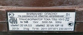
Current transformers are designated as follows: • T - The letter indicates that this is a current transformer • The second letter means the design: “P” - feed-through, “O” - support transformer, “Sh” - busbar, “F” - with a porcelain cover • The third designation indicates the insulation and cooling system of the transformer windings “L” - cast insulation, “M” - oil, Then it goes through the “-“ insulation class, climatic modification of transformers, and category of installations.
An example of decoding a current transformer TPL - 10UHL4 100/5A.
- T – current
- P – pass-through
- L – cast insulation
- Class 10 kV
- UH – temperate and cold climate
- 4 – fourth category
- 100/5A – transformation ratio is one hundred to five.
Examples of interpretation of voltage transformers: TM - 100/35 - three-phase oil transformer with natural circulation of air and oil, rated power 0.1 MVA, voltage class 35 kV; TDNS - 10000/35 - three-phase transformer with oil blowing, adjustable under load for the power plant’s own needs, rated power 10 MVA, voltage class 35 kV; VRTDNU - 180000/35/35 - boost transformer, regulating, three-phase, oil-cooled, type D, adjustable under load, with reinforced input, throughput power 180 MVA, rated voltage of the excitation winding 35 kV, rated voltage of the regulating winding 35 kV; LTMN - 160000/10 - linear transformer, three-phase, with natural circulation of oil and air, adjustable under load, throughput power 160 MVA, rated line voltage 10 kV. NKF-110-58U1 - cascade voltage transformer in a porcelain cover, rated voltage of the HV winding 110 kV, developed in 1958, climatic version - U1; NDE-500-72U1 - voltage transformer with a capacitive divider, rated voltage of the HV winding 500 kV, developed in 1972, climatic version - U1; TNP - 12 - zero-sequence current transformer, with alternating current bias, covering 12 cable cores; TNPSh - 2 - 15 - zero-sequence current transformer, with alternating current bias, busbar, covering 2 cable cores, rated voltage of the HV winding 15 kV.
Video: Classification of transformers
Having considered the marking features of various types of transformers, you can correctly use them at the site. Knowledge of the designations allows you to understand the functions and main technical characteristics of such equipment. The marking, which includes letters and numbers, complies with GOST standards used in the manufacturing process of special equipment.
Output for repair
The power transformer TRDN 110/35/10 kV is taken out for repair using operational switching forms. The latter are developed based on the primary connection diagram and the switching devices used. To carry out this task you will need:
- To remove it for repair, the load on the 10 and 35 kilovolt side is removed.
- Disconnection of the 110 kV side is carried out through a short circuit-isolator connection or using SF6 circuit breakers.
- The output of overlays and automation is carried out on the basis of a relay circuit. The TSN load is transferred. According to the mode, ZON-110 kV is turned on.
Grounding is carried out on each side from which voltage can be supplied. The grounding blades on the switch or on the transformer disconnector RLNDz-110 are turned on, the circuit breaker on the 35 kV MV is turned on, and portable grounding is installed on the 10 kV bus bridge.
Service Features
PTs are important links in power transmission schemes; the operation of the entire system depends on them. To ensure the reliability and uninterrupted operation of these devices, regular maintenance is required by trained specialists with the appropriate level of clearance.
If the equipment is used where the presence of full-time personnel on duty is provided, then their responsibilities include conducting regular inspections, during which readings are taken from instruments characterizing the current state of the equipment. The regulation requires monitoring:
- Oil level readings in heat sink systems.
- Condition of desiccant.
- Operation of the oil regeneration system.
- The condition of the external body of the device and its main components.
If deviations from the norm, leaks, damage or other signs indicating abnormal operation of the monitored devices are detected, personnel must take the measures prescribed by the instructions.
For autonomous equipment, the operation of which does not require the presence of on-duty personnel, technical inspection is required monthly. As for transformer points, for them this norm has been reduced to six months.
If a lack of oil is detected in the heat removal system, it should be topped up, and if it does not meet the standards, a complete replacement should be made. You can determine the need for an oil change by its color.
Evidence of abnormal equipment operation may be an increase in temperature in the substation room. If direct or indirect evidence of abnormal functioning of the equipment is detected, it is prescribed to conduct an unscheduled inspection to check the general condition of the elements of the protective equipment.
According to the operating rules, it is necessary to take an oil sample once a year for laboratory analysis. The same action is prescribed in case of major repairs.
In addition, during maintenance it is necessary to periodically adjust the operating voltage. The need for this is due to the fact that over time, brass and copper contacts become covered with an oxide film, which leads to an increase in contact resistance. To prevent this, once every six months the load and power are removed from the CT, after which the voltage regulator is switched in all positions. It is recommended to repeat the procedure several times before returning to the original position.
Completeness
Table 4 - Completeness
| №№ p/p | Name | Designation | Quantity | |
| 1 | SF6 current transformer | TRG-110 | TRG-220 | 1 |
| 2 | Single set of spare parts, tools and accessories | 0BP.433.854 | 0BP.438.437 | 1 |
| 3 | Passport | 1BP.769.001 PS | 1BP.769.002 PS | 1 |
| 4 | Manual | 1BP.769.001 RE | 1BP.769.001 RE | 1 |
| 5 | Packing list | 1BP.769.001 D1 | 1BP.769.002 D1 | 1 |
| 6 | SF6 gas cylinder | 1 | ||
Calculation of parameters
Figure 1.2 shows the equivalent circuit of a transformer with a split winding.
Figure 1.2 – Transformer equivalent circuit
Transformers with split winding are made with a winding power ratio equal to 100% / 50% / 50% [1]. For transformers with a split winding, the individual parameters are: – splitting resistance ZP (equal to the resistance between the terminals of the two branches of the split winding):
since the branches are the same:
– through resistance Zrms = ZV-N, equal to the resistance between the terminals of the high voltage winding and the combined (paralleled) branches of the split low voltage winding;
– coefficient of splitting of the CR is equal to:
The parameters of the equivalent circuit are determined by the following formulas:
To determine Z we use the formulas:
R is determined by the following formulas:
X will be calculated using the formulas:
kT H-B is determined by the formula: