Edited by: 10.03.2020
In a modern building, much attention is paid to the installation of the energy supply system. Even in an ordinary apartment, several hundred meters of cable are used, let alone large commercial or industrial facilities! A cable tray is a design that is indispensable when installing power systems, as it makes cable laying easier. It is usually made from metal that is treated with an anti-corrosion coating.
The use of metal cable trays can significantly increase the profitability of building operation and the reliability of utility networks, and also helps to avoid mechanical damage.
High-quality trays for cable management allow you to create systems of the most complex configurations, with various turns, fastenings and branches. Metal cable channels look neat and aesthetically pleasing, no matter what size they are or for what purpose they are installed. Galvanized steel trays are mounted both with and without a cover. The first option provides better protection of wires from environmental influences.
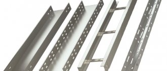
Cable laying trays come in the following types:
- solid,
- perforated,
- wire,
- staircases
Solid trays are suitable for rooms with high humidity. Perforated metal trays are lightweight, which greatly simplifies installation. They are used for laying cable routes to organize electrical systems in residential, office and commercial premises. The wire cable tray is laid in horizontal and vertical directions indoors. The ladder tray has a high load-bearing capacity and is used for installing power cables in workshops, administrative buildings, and residential buildings. Operated in open space.
What is important to know
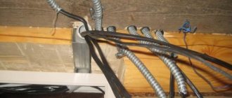
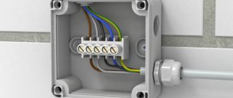
The main element of the electrical box design is a U-shaped profile, the length of which is 2 meters. The product kit includes a lid to close the internal cavity of the product. The profile is attached to the wall or ceiling, power cables or control wires are laid in it, after which the wiring is closed with a quick-release cover. The material from which the boxes can be made is galvanized steel, aluminum or durable plastic that does not support combustion. You can learn more about what types of cable channels there are in our separate article.
The range of products that perform cable channel functions is very diverse, as can be seen in the photo above. These can be wall boxes and floor skirting boards, as well as corrugated pipes and trays. As a rule, skirting boards are designed to accommodate low-current cables and wires; corrugated pipes and trays are used for installation in utility rooms and on the surface of external walls. For arranging the energy supply of premises, the most popular are wall-mounted electrical boxes made of plastic with a double-sided lock. In addition to the most common white cable channels, the industry has launched the production of products in a wide variety of colors that can complement the interior of any room.
Tags: sconce, view, harm, choice, house, , clamp, protective, cable, cable, how, design, crown, , tray, installation, voltage, rule, wire, project, laying, cable laying, start, , size, repair, row, garden, light, LED, ten, type, current, triangle, , installation, photo, shield
Cable tray sizes
Metal cable trays are produced in several standard sizes. This applies to the height of the side, and the length and width of the structure.
The height of the side varies from 30 to 200 mm, the length of the tray is from 2 to 3 m, the width of the base is from 50 to 800 mm, and the steel thickness is 0.7 - 2 mm. The choice of trays is made based on what you need to get in a particular situation. If you need to buy a cable tray of a certain standard size, then you need to buy your own set of accessories for it, and in each situation it is different, although it necessarily includes connectors and corner elements.
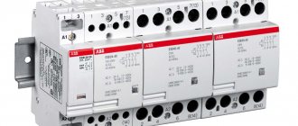
Installation of metal cable trays
Although each manufacturer includes instructions with the product, there are certain rules that apply to all types of iron trays. In particular, when choosing an installation method, the type of cable for which the tray itself is installed, the height of its installation, the type of fasteners used, and the features of the building are taken into account.
Additionally, although electrical wiring trays are almost always made of metal, different alloys can be used to make them. For example, not everyone has corrosion protection in the form of a zinc coating, but it is necessary to ensure the strength of the entire structure as a whole.
Advantages of cable management trays
When choosing trays for wires, you need to remember the advantages of metal products - strength and ability to withstand heavy loads. The designs also have other advantages:
- Easy to install. Does not require expensive tools. They are assembled using connecting elements or special connections.
- Wide range of sizes. Allows you to select elements that suit the client's requirements. Length - 2 - 3 meters.
- Reliability. Hanging cable trays have a curved top edge and a rounded turn shape, so the chances of damaging the insulating layer of the wire are minimized.
- Presence of holes. They allow cables to be routed along the entire length of the route.
- Resistance to external factors. The metal “channel” does not deform as a result of sudden temperature changes.
- The metal cable tray provides additional protection from shock, vibration and weather conditions.
- The price of a metal cable box with a lid depends on its type and type, but in general remains affordable.
If you have a choice of where to buy cable trays, choose a reliable one that has taken a leading position in the Russian market since 2007. Reasonable price and European quality are what distinguishes the company’s products from other organizations.
As-built documentation
The process of installing cable trays. Step-by-step instruction.
Good afternoon, dear builders, in this article I will describe in detail how to install cable trays step by step.
As a specific example, I took cable trays and mounting elements for them from BAKS. The designs of other manufacturers are similar.
First, let's get acquainted with the trays themselves and mounting elements visually...
1 Main stages of installation of cable trays.
- marking the route and installation sites for supporting structures;
- installation of supporting structures;
- installation of trays or load-bearing structures with elements of shaped products and fittings and marking;
- grounding of structures.
1.1 Marking the route and installation sites for supporting structures.
The trough route is marked with a laser level, while:
- the location of axes and marks is established according to the drawings;
- reconciliation is carried out according to the working drawings of the location of the trays;
- location marks and their intersections with process pipelines, ventilation ducts, AUPT pipes, etc. are checked;
- on building elements, the places of fastening of supporting structures are marked with a permanent marker;
- drilling or drilling holes in a wall or ceiling made of concrete (carried out using a hammer drill;
- clean the hole, insert the expansion bolt into the hole and hammer it in;
- install the mounted part and secure it with a bolt, screw or stud and nut.
Punching holes in corrugated sheets using the ceiling mounting method is done using MUPRO pliers.
When cutting all galvanized materials (trays, studs, shelves, etc.), to prevent further corrosion, Zinc Spray or an equivalent is applied to the cut areas.
1.2 Installation of supporting structures.
There are two types of tray mounting: wall and ceiling. The maximum distance, determined by the manufacturer, between the rods (attachment points, supports) is no more than 1.5 m:
1.2.1 Wall mounting.
The WMC/WMCO bracket, when mounted on a concrete wall (ceiling), is secured with expansion bolts PSROM10x80 (2 sets). The general view of the structure is shown in the figure:
The second way to mount the tray to the wall is to use a hinged rod suspension WPPGV/WPPOV. The fastening element in this case is also the PSRO expansion bolt.
1.2.2 Ceiling fastening to corrugated sheet.
With the ceiling mounting method, a trapezoidal V-shaped suspension WT/WTO and a PG M10 rod are first assembled at floor level. The suspension is attached to the rod on both sides using NS M10 nuts.
Next, a trapezoidal V-shaped suspension WT/WTO is installed using a PG M8 rod on the coating profile, which is secured on both sides with one NS M8 nut with PP8 washers placed underneath. The upper part of the suspension, if necessary, is bent to the required profile width.
The general view of the installed bracket and the assembly diagram of the unit are shown in the figure:
1.2.3 Ceiling fastening to concrete covering.
The rods are secured to the ceiling using TRS/TRSO steel spacer sleeves, pre-installed in marked and drilled holes.
Installation of channels.
After installing the bracket on the corrugated sheet, the reinforced channel CWP/CWOP40H40 is installed as a structural element for fastening cable ladders and cable trays. It is installed on the rods to the required height, which is adjusted using nuts and checked with a laser range finder. Each channel on each rod is secured on both sides using 2 NS M10 nuts with PP8 washers placed under them. When installing several channels, the distance between them should be 250 - 500 mm, as shown in the figure:
After securing the channel to the rods, the excess length of the rod is cut off using a hairpin cutter. In this case, the threads of the studs must protrude from the nuts by at least 25 mm. The maximum length is not regulated. To increase, if necessary, the length of the rods (studs), an extended connecting nut NLM10 is used, which is fixed with locknuts on both sides.
A complete diagram of the assembly of the fastening unit with the installed channel and tray is shown in the following figure:
1.3 Assembly and installation of trays.
To increase the pace of installation, if possible, blocks of 6-12 m are assembled from individual sections of trays at floor level, connecting them with bolted connecting strips. Enlarged blocks and individual sections of trays and blanks are delivered to the installation site, raised to the design height, routes are installed in the required places and the trays and sections are connected. After this connection, the tray is attached to the supporting structures and the horizontal installation is checked. Sections of cable trays, in addition to reliable mechanical connections, must have an unbreakable electrical connection with each other. Reliable mechanical and electrical connection for cable trays in accordance with the requirements for electrical conductivity in accordance with GOST R 52868-2007 Chapter 11 (IEC 61537:2006) is ensured using a set of SGM6x12 mushroom-head bolts and nuts with a toothed washer. When performing assembly operations, alignment of holes and checking their coincidence in mounted structural elements must be done using a special tool - conical mandrels, assembly plugs, etc. It is not allowed to check the coincidence of holes with your fingers. When cutting a tray, the cutting area is protected from burrs with a file and coated with zinc spray.
1.3.1 Straight perforated tray connections using connecting plates:
The KCP/KCOP trays are bolted together using the BL/BLO connecting plate and the LPP/LPOP connector using SGKM6x12 bolts. Connecting plate LPP/LPOP (2 pcs.) are attached from the inside to the side walls of adjacent trays with 4 screw sets SGKM6x12 through perforation holes located on the side walls of the trays: screw – from the inside, on the side of the plate, nut – from the outside, from the tray side. The BL/BLO connector is similarly attached to the bottom of adjacent trays. 6 sets of SKGM6x12 are used. The connection diagram is shown in the diagram and figure:
1.3.2 Connecting a straight perforated tray using bolts:
Possibility of assembling KCL/KCOL type trays by inserting one tray into another, installation is carried out without connectors. The use of connectors is recommended only for heavy loads. The trays are bolted together using SGKM6x12 bolts (position 2 in the figure). Fastening occurs through perforations located on the side walls of the trays: a screw - from the inside, on the plate side, a nut - on the outside, from the tray side.
1.3.3 Straight ladder connection:
Connecting plate LDC/LDOC (2 pcs.) are attached from the inside to the side walls of adjacent trays with 4 screw sets SGKM6x12 through perforation holes located on the side walls of the trays: screw - from the inside, on the plate side, nut - outside, from the tray side. The connection diagram is shown in the figure:
Install the assembled tray blocks in such a way that the tray is strictly horizontal. Check the correct installation of the tray using a level. The height of the trays is taken based on the design documentation. When crossing trays with pipelines, the distance to the nearest wire and cable must be at least 50 mm, and when laying parallel, at least 100 mm from them. If pipelines contain flammable liquids or gases, the crossing distances are increased to 100 mm, and when laid in parallel - at least 250 mm. Along horizontal routes, trays are placed flat, and on walls - with their ends on brackets, or in other ways specified in the design documentation. The free vertical distance between parallel trays must be at least 200 mm. Trays located near walls must be mounted at a distance of at least 50 mm from the wall so that cables can pass freely between the tray and the wall. The distance from the tray to the ceiling is at least 100 mm (subject to laying conditions). The distance between trays when installed in parallel with trays of other systems is at least 100 mm (subject to laying conditions). After laying the cables, the trays are closed with lids, if provided for by the project.
1.3.4 Changing the direction of the tray route in the horizontal plane:
To change the direction in the horizontal plane of the route, tees, corners, crosses and inserts into the tray are used. The tray to be connected and the specified mounting elements are butted tightly together and secured with screw sets through perforation holes located on the side walls and the bottom of the structure.
Tees. To connect the tee to trays, use at least 15 bolt sets SGK M6x12 for tray widths of 100 – 200 mm; — tray width 300 – 400 mm, at least 18 bolt sets SGK M6x12; — tray width 500 – 600 mm, at least 21 bolt sets SGK M6x12.
If necessary, instead of the TKBJ tee, you can use the radius version of the TKPJ tee. The technology for connecting this tee to trays is similar.
Angles. To connect corners with trays, use at least 10 bolt sets SGK M6x12 for tray widths of 100 – 200 mm; — tray width 300 – 400 mm, at least 12 bolt sets SGK M6x12; — tray width 500 – 600 mm, at least 14 bolt sets SGK M6x12.
If necessary, instead of the KKBJ angle, you can use the radius version of the KKPP/KKPOP tee. The technology for connecting this corner with trays is similar.
Cross. To connect the crosspiece with trays, use at least 20 bolt sets SGK M6x12 for tray widths of 100 – 200 mm; — tray width 300 – 400 mm, at least 24 bolt sets SGK M6x12; — tray width 500 – 600 mm, at least 28 bolt sets SGK M6x12.
If necessary, instead of the CZKBJ crosspiece, you can use the radius version of the CZKPP/CZKPOP crosspiece. The technology for connecting this corner with trays is similar.
Attached tee. Insets.
Composition of the unit: 1 - attached tee, 2 - tray, 3 - SGK M6x12 bolt.
To install an attached tee to trays, it is necessary to use at least 12 bolt sets; it is necessary to trim the side of the tray into which the tee will cut (marked with a red line).
This connection has a number of advantages: - the ability to make a branch in an existing flume route; — suitable for all perforations of BAKS trays; — the design provides better connection strength.
Installation of the support (mount).
When using the above methods of connecting the tray and the rotary structure, there must be a support (bracket, suspension, etc.) at the connection point. The recommended arrangement of supports is shown in the figures below. The maximum distance between supports of a standard design is 1500 mm.
Recommended supports when connecting a tray to a corner:
Recommended supports when connecting a tray with a T-bend:
1.3.5 Changing the direction of the tray route in the vertical plane.
To change the direction in the vertical plane of the route, an LGP/LGOP hinged connector is used. The swivel joint combines the functions of a connector and a rotation angle (see Fig. 2). It allows you to change the direction of the cable channel in the vertical plane at an arbitrary angle. Compared to vertical angles of 90 degrees. a swivel joint is a simpler and more economical solution. It consists of two sets of LGP/LGOPH strips connected by a screw and a nut. To install the swivel joint to the tray, use 4 sets of SGKM6x12 bolts. To protect cables from damage, a BZK/BZKO end plate or a BL/BLO connecting plate should be used at the ends of the trays. To attach the end plate to the tray, use: - width 100-200 mm - at least 2 sets of bolts SGKM6x12; — width 300-400 mm — at least 3 sets of bolts SGKM6x12; — width 500-600 mm — at least 5 sets of bolts SGKM6x12. The assembly of this unit is shown in the figure:
Avoiding obstacles using articulated connectors (arcs). The main method of avoiding obstacles is the articulation technology, which can be used both to bypass structures of various kinds, and to lower/raise the route to a different level. For one connection of two trays, it is necessary to use two hinged connectors LGP/LGOP or one hinged arch LLP/LLOP...H60.
Drawing. Transition from a vertical tray to a horizontal one.
To install two hinged connectors to the trays (or one hinged arch), use 8 bolt sets SKG M6X12.
You may be interested in: “How to mark cables when laying them.”
In places where lifting/lowering occurs after the tray using hinged connectors/arcs, it is necessary to install a BZK/BZKO closing plate on the edge of the tray before/after lifting/lowering on the bottom of the tray in order to strengthen the tray and prevent damage to the cable during installation. It is allowed to use a connecting plate BL\BLO instead of a closing plate.
To connect the tray to the end/connecting plate, you must use: - with a tray width of 100 – 200 mm. At least 4 sets of SKGM M6x12 bolts; — with a tray width of 300 – 400 mm. At least 6 sets of SKGM M6x12 bolts.
1.3.6 Avoiding obstacles from below:
1.3.7 Avoiding obstacles from above:
1.3.8 Avoiding obstacles using corner joints:
1.3.9 Changing the width of the tray route.
To switch to another width, as well as to connect tray lines of different widths, left, right or symmetrical reduction is used: RKLP, RKLBJ, RKPP, RKPBJ, RKSP, RKSBJ.
Examples of reductions and an image of the installation of a symmetrical reduction are given below:
Scheme and image of installation of an angular reduction:
1.3.10 Attaching the tray to supporting structures:
The supporting structures when installing trays are elements of prefabricated cable structures. The tray is attached to the CWP/CWOP channel using 3 sets of SGKM6x12.
Installing the tray on a channel with fastening to a ceiling bracket. (The distance between supports is no more than 1500 mm.).
Attaching the tray to the wall bracket.
To attach ladder trays to the WMC/WMCO bracket, the following are used: ZM/ZMO clamp and 2 sets of SGKM6x12.
1.3.11 Passage of tray routes through walls:
To make passages through wall barriers, the following is used: - For sandwich panels - a jigsaw; — For brick and concrete – a hammer drill with a set of attachments. After laying the cables (wires) on the trays, the holes are sealed and sealed with a fire retardant compound in accordance with TK-VB-007-KP.
1.3.12 Attaching the PMO junction box:
To fasten: — the box to the holder, use a SMM6x16 bolt (set with box); — apply a bolt SGKM6x12 to the tray. The figure shows the installation of a box on a tray with fastening through the UPU box holder.
1.4 Grounding of structures.
For grounding, connect cable trays with a grounding conductor at the beginning and end of the tray route. Cable trays must be connected to the main potential equalization system. The connection is made with a 6 mm2 copper conductor. In each specific case of installation of a tray route, it is necessary to apply solutions for the grounding point.
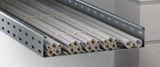
Example of finished installation of trays:
That's all I have. Thank you for your attention.
See the composition of the executive in the section: “Composition of the executive”
Download acts, protocols and more in the section: “Acts and other”
Download useful books, GOSTs, SNIPs in the section: “GOSTs and books“