Hello, dear readers of the site. Inductor is one of the elements without which it will not be possible to build a receiver, TV, radio-controlled model, transmitter, signal generator, modem converter, surge protector, etc.
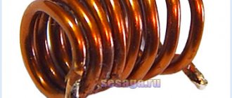
An inductor or simply a coil can be thought of as several turns of wire wound in a spiral. The current passing through each turn of the spiral creates a magnetic field in them, which, intersecting with neighboring turns, induces self-induction emf in them. And the longer the wire and the greater the number of turns it forms, the greater the self-induction.
GENERAL ELECTRICAL ENGINEERING AND ELECTRONICS. ELECTRICITY AND MAGNETISM
|
Inductor
- is a passive component of electronic circuits, the main purpose of which is to store energy in the form of a magnetic field. The property of an inductor is somewhat similar to a capacitor, which stores energy in the form of an electric field.
Inductance (measured in Henry) is the effect of creating a magnetic field around a current-carrying conductor. The current flowing through the inductor creates a magnetic field, which has a relationship with the electromotive force (EMF) that opposes the applied voltage.
The resulting reaction force (EMF) opposes the change in alternating voltage and current in the inductor. This property of an inductive coil is called inductive reactance. It should be noted that the inductive reactance is in antiphase to the capacitive reactance of the capacitor in the AC circuit. By increasing the number of turns, the inductance of the coil itself can be increased.
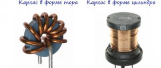
Variometers
In the antenna circuits of shortwave transmitters and special VHF receivers, variometers with a variable number of turns are used. Such a variometer consists of a cylindrical or conical frame with a spiral groove in which the coil wire is laid. A contact roller or spring brush is pressed against the part of the wire protruding above the frame, which, when the coil rotates, slides along the turns and moves in a plane parallel to the generatrix of the cylinder or cone.
Thus, it becomes possible to introduce the required number of turns into the circuit, i.e., obtain the required inductance. In the symbol of a variometer of a similar design, the roller or brush is depicted in the form of an arrow, the tip of which touches the convex part of the semicircle of the main symbol. Variometers are characterized by a smooth change in inductance. To change it stepwise, as well as in some other cases, taps are made at the coils.
Material on the topic: all about the variable capacitor.
Stored energy in inductance
As you know, a magnetic field has energy. Just as there is a reserve of electrical energy in a fully charged capacitor, there is also a reserve of magnetic energy in an inductive coil through the winding of which current flows.
The energy stored in the inductor is equal to the expended energy necessary to ensure the flow of current I in counteracting the EMF. The amount of stored energy in the inductance can be calculated using the following formula:
where L is the inductance, I is the current flowing through the inductor.
Alternatives to NFC technology
All payment terminals are still capable of reading cards with magnetic stripes. An alternative to NFC technology is Magnetic Secure Transmission (MST), which appeared in LG Electronics phones in June 2022 and will soon appear in Samsung phones. A phone with MST equipment emulates the magnetic stripe on any payment card. Instead of swiping the card across a reader, the phone sends a "magnetic signal" in the form of a changing magnetic field, which is read by the magnetic head of the payment terminal. This technology can be used on all existing payment terminals without any changes on the part of merchants. To make a payment, a smartphone with a chip and an MST coil generates an alternating magnetic field with a strength sufficient to be read by the magnetic head of a payment terminal at a distance of 8 cm. Before you start paying with your phone, the user must enter information about their payment cards into it. As a result of entering card information, the phone turns into a digital wallet.
Author of the article: Anatoly Zolotkov
Hydraulic model
The operation of an inductor can be compared to the operation of a hydraulic turbine in a flow of water. The flow of water directed through a turbine that has not yet been spun up will feel resistance until the turbine is completely spun up.
Next, the turbine, which has a certain degree of inertia, rotates in a uniform flow, practically without affecting the speed of water flow. If this flow is suddenly stopped, the turbine will still rotate by inertia, creating water movement. And the higher the inertia of a given turbine, the more it will resist changes in flow.
Also, an inductive coil resists changes in the electric current flowing through it.
Inductance in electrical circuits
While a capacitor resists changes in alternating voltage, inductance resists alternating current. An ideal inductance will have no resistance to direct current, however, in reality, all inductive coils themselves have a certain resistance.
In general, the relationship between the time-varying voltage V(t) passing through a coil of inductance L and the time-varying current I(t) passing through it can be represented as a differential equation of the following form:
When a sinusoidal alternating current (AC) flows through an inductor, a sinusoidal alternating voltage (EMV) is generated. The amplitude of the EMF depends on the amplitude of the current and the frequency of the sinusoid, which can be expressed by the following equation:
where ω is the angular frequency of the resonant frequency F:
Moreover, the phase of the current lags behind the voltage by 90 degrees. In a capacitor, the opposite is true, where the current leads the voltage by 90 degrees. When an inductive coil is connected to a capacitor (series or parallel), an LC circuit is formed that operates at a specific resonant frequency.
Inductive reactance XL is determined by the formula:
where XL is the inductive reactance, ω is the angular frequency, F is the frequency in hertz, and L is the inductance in henry.
Inductive reactance is the positive component of impedance. It is measured in ohms. The impedance of the inductor (inductive reactance) is calculated by the formula:
Characteristics of elements
The exceptional parameters of this device include the following:
- They have high inductance;
- Suitable for different current strengths, which you need to pay attention to when used in different devices;
- Loss of resistance in conductors, cores, and other elements;
- High efficiency in use;
- Turn capacitance may be parasitic;
- Inductance and its changes affect the temperature coefficients of the device;
- Quality factor values may depend on temperature.
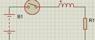
Inductor connection diagrams
Parallel connection of inductors
The voltage across each of the inductors connected in parallel is the same. The equivalent (total) inductance of parallel-connected coils can be determined by the formula:
Series connection of inductors
The current flowing through inductors connected in series is the same, but the voltage across each inductor is different. The sum of potential differences (voltages) is equal to the total voltage. The total inductance of series-connected coils can be calculated using the formula:
These equations are valid provided that the magnetic field of each coil does not affect neighboring coils.
Inductor quality factor
In practice, an inductor has a series resistance created by the copper winding of the coil itself. This series resistance converts the electric current flowing through the coil into heat, which leads to a loss of induction quality, that is, quality factor. Quality factor is the ratio of inductance to resistance.
The quality factor of the inductor can be found through the following formula:
where R is the winding's own resistance.
Marking
To indicate the rating of the inductor, letter or color markings are used. There are two types of letter markings.
- Designation in microhenry.
- Designation by a set of letters and numbers. The letter r is used instead of a decimal point, the letter at the end of the designation indicates the tolerance: D = ±0.3 nH; J = ±5%; K = ±10%; M = ±20%.
The color markings can be recognized in a similar way to those on resistors. Use the table to decipher the colored stripes or rings on the element. The first ring is sometimes made wider than the others.
This is where we finish considering what an inductor is, what it consists of and why it is needed. Finally, we recommend watching a useful video on the topic of the article:
Inductor. Inductance formula
Basic formula for coil inductance
- L = inductance in henry
- μ 0 = permeability of free space = 4π x 10 -7 H/m
- μ g = relative permeability of core material
- N = number of turns
- A = Cross-sectional area of the coil in square meters (m2)
- l = coil length in meters (m)
Direct conductor inductance
- L = inductance in nH
- l = conductor length
- d = conductor diameter in the same units as l
Air core coil inductance
- L = inductance in µH
- r = outer coil radius
- l = coil length
- N = number of turns
Inductance of Multilayer Air Core Coil
- L = inductance in µH
- r = average coil radius
- l = coil length
- N = number of turns
- d = coil depth
Flat Coil Inductance
- L = inductance in µH
- r = average coil radius
- N = number of turns
- d = coil depth
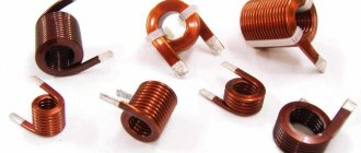
Inductor design
An inductor is a winding of conductive material, usually copper wire, wound around either an iron-containing core or no core at all.
The use of materials with high magnetic permeability, higher than air, as a core helps to retain the magnetic field near the coil, thereby increasing its inductance. Inductive coils come in different shapes and sizes.
Most are made by winding enameled copper wire over a ferrite core.
Some inductive coils have an adjustable core that allows the inductance to vary.
Miniature coils can be etched directly onto the PCB in a spiral pattern. Low-value inductors can be located in microcircuits using the same technological processes used to create transistors.
Identity theft using RFID devices
Data read by mobile phone using Credit Card Reader mobile application
In preparation for this article, I performed a simple test: I downloaded the Credit Card Reader app from Google Play and held my phone against a wallet that contained unused credit cards. Information from one of the cards appeared on the phone: my first and last name, the name and number of the credit card, the expiration date of its use, the name of the organization that issued the card and a list of the last ten transactions. It is clear that with the help of more serious equipment (a more powerful transmitter and a good, highly sensitive receiver), this information can be obtained not only by applying the device to the wallet, but also at a short distance, maybe half a meter from the wallet. Of course, this equipment will not be able to read the PIN or three-digit code on the back of the card. However, a thief can use information about such a card to make purchases in some online stores, since not all sellers include the option to verify the three-digit code. Some people turn it off for the convenience of customers. No comments needed.
Application of inductors
Inductors are widely used in analog and signal processing circuits. They combine with capacitors and other radio components to form special circuits that can amplify or filter signals of a specific frequency.
Inductors have a wide range of applications ranging from large inductors such as power supply chokes that, in combination with filter capacitors, eliminate residual noise and other oscillations in the power supply output, to as small inductors as those found inside integrated circuits.
Two (or more) inductors, which are connected by a single magnetic flux, form a transformer, which is the main component of circuits operating with an electrical power supply network. Transformer efficiency increases with increasing voltage frequency.
For this reason, aircraft use AC voltage with a frequency of 400 hertz instead of the usual 50 or 60 hertz, which in turn allows for significant savings in the mass of transformers used in the aircraft power supply.
Inductors are also used as energy storage devices in switching voltage stabilizers, in high-voltage electrical power transmission systems to deliberately reduce system voltage or limit short-circuit current.
Applications for smartphones, NFC tags and cards
If you use one of the many apps available on Google Play, you can encode NFC tags to perform various tasks, such as
- Change the operating modes of the GPS navigator, Wi-Fi and Bluetooth on your smartphone (turn it on or off).
- Change sound and volume settings (ringer, quiet, loud, vibration only, notification sound, system sounds and alarm volume, vibration on and off).
- Change display settings, such as brightness, auto rotation, turn-on time, and others.
- Interaction with social networks and social media, for example, you can quickly post a photo to a blog.
- Send a message by email or text.
- Open and close applications, open URL.
- Call someone.
- Create various other tasks for NFC tags.
Operating principle of near-contact communication: 1 - NFC reader processor chip, 2 - reader, 3 - NFC tag, 4 - load modulator, 5 - NFC tag chip, 6 - inductive coupling, 7 - data is sent to the load modulator
What happens if you bring your phone with NFC enabled closer to the NFC tag? Suppose you are getting ready to go to bed and touch your phone to the “Alarm Clock” label stuck on your bedside table. The phone periodically activates the NFC chip, which sends a 13.56 MHz AC signal to the loop antenna on the back of the phone. The antenna produces a weak electromagnetic field. This field induces an alternating current in the NFC tag's loop antenna, which is rectified and charges the tag's capacitor. The energy stored in the capacitor is used to power the tag chip, which in turn also generates an alternating current that contains the command to turn on the alarm clock on the phone. The smartphone chip detects the electromagnetic field of the NFC tag loop antenna and decodes the received information. After decoding, the phone runs an alarm program that turns it on.
NFC tag
Calculation of inductors
Any conductor carrying current creates a magnetic field around itself. The ratio of the magnetic flux of this field to the current generating it is called inductance. The inductance of a straight piece of conductor is small and amounts to 1...2 µH per meter of length, depending on the diameter of the wire (thin conductors have a higher inductance). The formula gives more accurate results
where is the length of the wire; d is its diameter. Both sizes must be taken in meters (under the logarithm sign it is permissible in any, but identical units), the inductance will be in microhenry. To make calculations easier, recall that the natural logarithm of any number is 2.3 times the decimal logarithm (which can be found using tables, a slide rule or a calculator), i.e. Inx = 2.3lgx.
Why did we give this formula? Let's explain with an example.
Let the leads of a certain radio element have a length of 4 cm and a diameter of 0.4 mm. Let's calculate their inductance:
2.3lg100 = 4.6 and 0.2-0.04-3.6 = 0.03 (rounded).
So, the inductance of each pin is close to 0.03 μH, and the inductance of two pins is 0.06 μH. With a capacitance of only 4.5 pF (and the mounting capacitance can be higher), such an inductance forms an oscillating circuit tuned to a frequency of 300 MHz - remember Thomson’s formula:
f = 1/2π√LC.
This is why installation on VHF cannot be done with long wires and long leads of parts should not be left.
To increase the inductance, the conductor is rolled into a ring. The magnetic flux inside the ring increases, and the inductance becomes approximately three times greater:
L = 0.27πD(ln8D/d-2).
Here D is the diameter of the ring, the dimensions are the same. A further increase in inductance occurs with an increase in the number of turns, while the magnetic fluxes of individual turns not only add up, but also affect all other turns. Therefore, inductance increases in proportion to the square of the number of turns. If there are N turns in the coil, the inductance obtained for one turn must be multiplied by N2.
For a single-layer cylindrical coil with a length much greater than the diameter D (Fig. 23), the inductance is calculated quite accurately using the formula
strictly derived for a very long solenoid or torus. All dimensions here are in the SI system (meters, Henry), μ0 = 4π·10-7 H/m - magnetic constant; S = πD2/4 is the cross-sectional area of the coil; μ is the effective magnetic permeability of the magnetic circuit. For open magnetic cores, it is significantly less than the permeability of the material itself. For example, for a magnetic antenna rod made of ferrite grade 600NN (magnetic permeability 600) and barely reaches 150. If there is no magnetic circuit, μ = 1.
This formula gives very accurate results for toroidal coils, and l
corresponds to the circumference of the ring magnetic circuit, measured along its center line. The formula is also suitable for low-frequency transformers wound on an W-shaped magnetic core (Fig. 24).
In this case, S = ab is the cross-sectional area of the magnetic core, and l
is the average length of the magnetic field line, shown in the dotted line in the figure.
For closed magnetic cores assembled without a gap, as for ferrite rings, and is taken equal to the magnetic permeability of the material. A small gap slightly reduces μ. Its influence can be taken into account by increasing the length of the magnetic field line l
by the value δμ, where δ is the gap width, μ is the magnetic permeability of the core material.
As you can see, inductance practically does not depend on the diameter of the wire. For low-frequency coils, the wire diameter is selected based on the permissible current density, for copper conductors 2...3 amperes for each mm2 of conductor cross-section. In other cases, especially with RF coils, one strives to obtain a minimum conductor resistance in order to increase the quality factor (the ratio of inductive to active reactance).
For this purpose, it would seem that it is necessary to increase the diameter of the wire, but then the length of the winding increases, which reduces the inductance, and with a close, multi-layer arrangement of turns, the effect of “displacing” the current from the winding is observed, which increases the resistance. The effect is similar to current displacement at high frequencies in any conductor, resulting in current flowing only in a thin skin layer near the surface of the conductor. The skin layer thickness decreases, and the wire resistance increases in proportion to the square root of the frequency.
Thus, to obtain the required inductance and quality factor, it is not at all necessary to choose the thickest wire. For example, if a single-layer coil (see Fig. 23) is wound with thick wire turn to turn or with twice as thin wire, but with a step equal to the diameter of the wire, the inductance will remain the same and the quality factor will hardly decrease. The quality factor increases as all dimensions of the coil increase along with the diameter of the wire, mainly its diameter.
To obtain maximum quality factor and inductance, it is more advantageous to make the coil short, but of large diameter, with a ratio D/ l
about 2.5. The inductance of such coils is more accurately calculated using the empirical (experimentally selected) formula
where the dimensions are taken in centimeters, and the inductance is obtained in microhenry. Interestingly, the same formula applies to a spiral or basket flat coil (Fig. 25).
The average diameter is taken as D:
D = (Dmax + Dmin)/2
and as l
- winding width,
l
= (Dmax - Dmin)/2.
The inductance of a multilayer coil without a core (Fig. 26) is calculated by the formula
where the dimensions are substituted in centimeters, and the inductance is obtained in microhenry. With dense ordinary winding, the quality factor does not exceed 30...50, “loose” winding (in bulk, universal) gives high quality factor values. Even better is the “cellular” winding, now almost forgotten. At frequencies up to 10 MHz, the quality factor increases when using Litz wire - a wire twisted from many thin insulated strands. Litz wire has a larger total wire surface, through which current actually flows due to the skin effect, and therefore has less resistance at high frequencies.
A magnetodielectric trimmer increases the inductance up to 2-3 times, depending on the size of the trimmer. An even greater increase in inductance is provided by closed or partially closed magnetic circuits, for example, pot-shaped ones. In this case, it is better to use the strict formula for a solenoid or torus (see above). The quality factor of a coil on a closed magnetic circuit is determined not so much by the wire as by losses in the core material.
To conclude the chapter, we present several useful formulas for calculating the active resistance of wires. The linear resistance (per meter of length) of a copper wire at direct current and low frequencies (Ohm/m) can be easily found using the formula
FL = 0.0223/d2,
where d is the diameter of the wire, mm. Skin thickness for copper (mm) is approximately 1/15√ f
(MHz). Please note: already at a frequency of 1 MHz, the current penetrates the wire to a depth of only 0.07 mm! In the case where the wire diameter is greater than the skin layer thickness, the resistance increases compared to the resistance at direct current. The linear resistance of the wire at high frequency is estimated using the formula
R = √f/12d (mm).
Unfortunately, these formulas cannot be used to determine the active resistance of coils, since due to the effect of the proximity of the turns, it turns out to be even greater.
Contactless communication (NFC)
It appears that in the future, an NFC-enabled phone will be used instead of a wallet for loyalty cards and credit cards. So what is NFC? This is a wireless communication technology over a short distance (up to 10 cm) at a high frequency (13.56 MHz), allowing data exchange between two electronic devices, one of which is usually a smartphone, and the other is an NFC tag, contactless card or reader. Like other RFID technologies (and NFC is part of these technologies), NFC uses electromagnetic induction between two loop antennas when two devices exchange information on the unlicensed ISM (Industrial, Scientific and Medical) high-frequency band in most countries. medical) with an exchange rate of 100–400 kbit/s. The connection is usually established in less than a second, and it takes 1-5 seconds to transfer a 40-kilobyte image. The great convenience of NFC is that it can be used in conjunction with Bluetooth to pair two devices without a password.
Due to the fact that the ISM band used for NFC is between the broadcast shortwave bands of 22 meters (13.57-13.87 MHz) and 25 meters (11.6-12.2 MHz), the communication audio between the smartphone and NFC and a passive tag can be easily heard on a regular shortwave broadcast receiver if you place the phone with the tag near the antenna.
There are three NFC operating modes:
- Direct communication mode between two devices that can operate in NFC mode; for example, it could be two smartphones that communicate with each other.
- Read and write - a mode in which an active NFC device, usually a smartphone, reads information from a passive NFC device (usually an NFC tag); The smartphone can also write information to the tag.
- Payment card emulation is a mode in which an NFC device, usually a smartphone, acts as a contactless card; this allows you to pay for purchases in stores or pay for travel on public transport by bringing it closer to the payment terminal
NFC antenna under the glass back wall of the Xiaomi Mi5 smartphone, which was used for experiments in preparing this article
Using these three operating modes, NFC allows users to transfer information from one smartphone to another, pay for purchases by simply holding the smartphone to a payment terminal, or use the smartphone as an electronic ticket on public transport in a similar way. NFC devices are also used when communicating on social networks, as they allow you to easily exchange contact information by touching one NFC phone to another NFC phone.
It is clear that the ability to use NFC devices to communicate on social networks is increasingly being used to promote goods and services. For example, visitors can touch their phone to NFC tags or simply place the phone on a table with NFC tags attached in a restaurant or bar, and information about their location will be immediately updated on social networks. With just a swipe of their phone, shoppers can post to their Facebook or Twitter accounts about items they like in the store. NFC tags will allow customers to upload information about store hours and location and quickly share it with their friends.
Using an NFC phone, it is easy to check the operation of the biometric passport chip. This can be done, for example, before going on vacation abroad, to be sure that the electronic passport is functioning correctly (isn’t it a somewhat strange combination - a faulty passport?). All you need to do is download the ReadID - NFC Passport Reader application from Google Play (apple phone users, please do not worry - their devices do not yet support all the NFC modes described here, except for payment for services). Take a photo of the machine-readable area of the passport with your phone, then attach the passport to the phone and read the contents of the passport microcircuit. That's all. The application will show you your photo and all the information obtained from the chip. This information is stored in the electrically erasable programmable ROM (EEPROM) of the passport chip. To read passport information, you must first enter the date of birth, date of issue and passport number into the microchip. Some applications allow you to enter this information manually. In our example, it is entered by photographing the machine-readable area with a phone camera. If a passport is scanned, for example, at an airport, then the cryptographic signature stored in the chip must also be checked there. According to some reports, not all airports actually carry out such verification yet, which means that sometimes you can travel with a fake digital passport.