One of the most important points when installing a SIP wire is to give it the correct tension.
When constructing VLI and VLZ, you can use modern and super-expensive tools and devices (motor winch), use reliable European fittings (Ensto and Sicame), but if you make a mistake in just one moment, roughly speaking, tighten the SIP more than required, and in a year all your the work will go down the drain.
The winter period of operation with our frosts does not forgive such mistakes.
Of course, any electrician understands that neither SIP, nor bare wires A or AC, and even modern innovative AEROZ cannot be pulled into a string.
Although this is visually beautiful from the outside, it significantly reduces the reliability of the operating overhead line. Even supports that can easily withstand large bending moments will begin to bend and tilt.
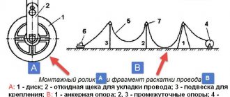
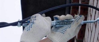
Or one of the anchor elements will not withstand the load and will break off. When installing the hook correctly on the support, the lock on the bandage tape must first come loose.
The SIP itself will fall to the ground without serious damage to the shell. But the installation of reinforcement is not always carried out using steel banding tape.
Through hooks are often used.
How to correctly calculate the tension of an insulated line with SIP wires, so that at low temperatures large bending moments do not appear, and the wire itself and the fittings are not subjected to increased loads?
Installation tables for SIP
Assembly tables will help you in this matter. They are present in almost any typical project.
You can view and download tables of tension and calculated sag (from Ensto) for SIP-4 wire from here (from page 32 to page 104).
However, do not forget to recalculate the mounting tension throughout the entire wire. Since the plates contain data on mechanical stress.
Also, to convert mPa into a more convenient format kgf or kN, used on dynamometer scales, you can use a convenient online converter using the link here.
Let's look at two extreme cases as an example:
- During installation, a minimum cross-section of 4*25 is used
- and vice versa maximum 4*120
From the tabular data you can clearly see how the SIP sag of a correctly tensioned wire changes depending on the temperature.
With a span length of 30 meters between the supports and a temperature of +20C, the sag should be about half a meter. The tension for the same wire does not exceed 84 kg.
This is not a very large value, and many are tempted to pull the line tighter. Fortunately, this can be done even manually by two or three fitters, without the use of special winches.
However, in winter, when the ambient temperature stays below 20 degrees for a long time and reaches -30C, everything changes dramatically. A correctly tensioned SIP with a cross section of 25mm2 already sags by only 14cm! And if you tighten it a little in the summer, then this is where the extra bending and tearing forces arise.
This is all transferred to the supports and anchor clamps. At -30C, the gravity increases 4 times and reaches 323 kg.
For SIP 4*120 at t=+20C, the sag will be 86cm. And at -30C it will rise to 0.6m. On the one hand, visually the difference here will not be so noticeable.
However, look at the gravitational force for yourself. Even in summer it exceeds 200 kg, not to mention the winter maximum or ice.
All these tables are designed in such a way that under any circumstances, even the worst (temperature minus 40C or minus 5C, but with ice), the gravitational forces are achieved to the maximum possible, but at the same time do not go beyond the norm.
That is, if in the summer under good weather conditions you pull the wires according to the table, and not “by eye,” then in the winter, even in the worst case scenario, nothing will break or break.
Installation tables and sag for high-voltage SIP-3 can be downloaded from here (Design Guide - Book 4.1 page 26-50).
The SIP wire itself is very durable. It differs significantly in its properties from the uninsulated bare speaker wire.
Therefore, you cannot pull it into a string.
If you do not have special measuring dynamometers, then it is better to let it sag. The main thing is to ensure clearance above the road.
At least there will be no overloads or emergency shutdowns due to this. And VLI-0.4 kV will quietly serve its allotted 40 years.
How to use these tables in practice in real conditions? In order to correctly stretch the SIP line along them, you can use two methods:
- use a dynamometer
- manually measure the sag in one span
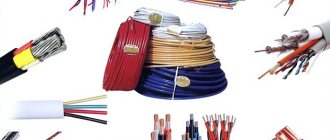
Wire brands
For electrical wiring, it is best to use two brands of wires - VVGng and VVG.
The first one has the ending “-ng”, which indicates that the insulation does not burn. It is used for electrical wiring inside structures and buildings, as well as in the ground, in the open air. It works stably in the temperature range -50... 50. Make sure that there is no letter “A” before the name of the wire (for example, AVVG). This suggests that the cores inside are made of aluminum. There are also foreign analogues - the NYM brand cable, which has a round shape, meets the standards adopted in Germany (VDE0250). The conductors are copper, the insulation is not subject to combustion.
SIP tension through a dynamometer
When using a dynamometer, the tension force taken from the table alone is not enough. It is also necessary to know the given anchor span. What it is?
This is a span or spans on an overhead line between two anchor supports. Between them there can be either one or several intermediate supports.
At the same time, the calculation tables indicate data specifically for the given spans. They represent a certain average mathematical value.
This is due to the fact that the lines are not always uniform. And the distances between the supports sometimes differ by several tens of meters.
Let's say you have two anchors and one intermediate support between them. The length of the first span is 40 meters, and the second is only 10 m. It is clear that with the same tension, in a larger span the sag of the boom will always be greater.
Therefore, the gravity itself is determined precisely for the average value. The average reduced span is calculated using the following formula:
- Li is the length of one span in meters or km
- ∑Li – sum of all spans
By calculating the value using this formula, you will get the final reduced span. For our case (40m+10m) it will be 25m.
Next, using interpolation in the table, we look for the required tension. In the tabular data for spans up to 40m, the values are divided in 2m increments.
For longer distances, integer values of 40-45-50m are usually used. You will need to find the closest one.
Having found out the required value, tension the SIP on the final support through a dynamometer.
In order to do this correctly, simply monitor the readings of the scale of the measuring device so as not to go beyond the limits of this effort.
PUE recommendations
Pue 7. rules for electrical installations.
edition 7 But you can use a set of rules and standards. There is such a document as the Electrical Installation Rules, which regulates all the rules for installing wiring not only in private property, but also in factories, factories, etc. According to these rules, the standard for electrical wiring is the ability to withstand a load of 25 amperes for a long time.
To ensure that all electrical wiring operates as safely as possible, a circuit breaker is installed at the input. It will protect the apartment from short circuits. Also, recently, most homeowners have been installing residual current devices, which instantly change the resistance in the circuit.
In other words, if you accidentally touch exposed live wires, they will immediately de-energize and you will not receive a shock. Automatic switches must be calculated based on current, and they must be chosen with a reserve so that it is always possible to install any electrical appliance in the house.
2.5.238
When crossing an overhead line with an underground communication cable and a power supply (or with an underground cable insert), the following requirements must be met:
1) the angle of intersection of overhead lines up to 500 kV with LS and LPV is not standardized, the angle of intersection of 750 kV overhead lines with LS and LPV should be as close as possible to 90°, but not less than 45°;
2) the distance from underground cables LS and LPV to the nearest ground electrode of an overhead line support with voltage up to 35 kV or its underground metal or reinforced concrete part must be at least:
in populated areas - 3 m;
in uninhabited areas - the distances given in Table 2.5.26.
Table 2.5.26 Shortest distances from underground cables LS (LPV) to the nearest ground electrode of the overhead line support and its underground part
| Equivalent earth resistivity, Ohm m | Shortest distance, m, at overhead line voltage, kV | ||
| Up to 35 | 110-500 | 750 | |
| Up to 100 | 10 | 10 | 15 |
| More than 100 to 500 | 15 | 25 | 25 |
| More than 500 to 1000 | 20 | 35 | 40 |
| More than 1000 | 30 | 50 | 50 |
The distance from underground LAN and LPV cables to the underground part of an ungrounded wooden support of an overhead line with voltage up to 35 kV must be at least:
in populated areas - 2 m; in cramped conditions, the specified distance can be reduced to 1 m, provided that the cable is laid in a polyethylene pipe at a length on both sides of the support of at least 3 m;
in uninhabited areas: 5 m - with an equivalent earth resistivity of up to 100 Ohm m; 10 m - with an equivalent earth resistivity from 100 to 500 Ohm m; 15 m - with an equivalent earth resistivity from 500 to 1000 Ohm m; 25 m - with an equivalent earth resistivity of more than 1000 Ohm m;
3) the distance from the underground cables of LAN and LPV to the nearest ground electrode of the overhead line support of 110 kV and above and its underground part must be no less than the values given in Table 2.5.26;
4) when laying an underground cable (cable insert) in steel pipes, or when covering it with a channel, an angle, or when laying it in a polyethylene pipe, closed on both sides from the ingress of earth, at a length equal to the distance between the overhead line wires plus 10 m with on each side from the outermost wires for overhead lines up to 500 kV and 15 m for overhead lines 750 kV, it is allowed to reduce the distances indicated in Table 2.5.26 to 5 m for overhead lines up to 500 kV and up to 10 m for 750 kV.
In this case, the metal covers of the cable should be connected to a pipe or other metal protective elements. This requirement does not apply to optical cables and cables with an external insulating hose, including those with a metal sheath. The metal covers of the cable insert must be grounded at the ends. When reducing the distances between the cable and the overhead line supports specified in Table 2.5.26, in addition to the given protection measures, it is necessary to install additional protection against lightning strikes by lining the supports with cables in accordance with the requirements of regulatory documentation for the protection of cables from lightning strikes;
5) instead of using a channel, angle or steel pipe, when constructing a new overhead line, it is allowed to use two steel cables with a cross-section of 70 mm, laid symmetrically at a distance of no more than 0.5 m from the cable and at a depth of 0.4 m. The cables must be extended on both sides at an angle of 45° to the route towards the overhead line support and grounded to a resistance of no more than 30 Ohms. The relationship between the length of the cable outlet and the grounding resistance must correspond to the values and given in Table 2.5.27;
Table 2.5.27 Resistance of grounding conductors when protecting LAN and LPV cables at the intersection with overhead lines
Find a
In the previous section, we were unable to present the equation of the first parameter of the chain line: .
This happened because in this case there is no concise solution that can calculate its exact value. In fact, any attempt at derivation will lead us to the following transcendental equation: In other words, we cannot transform this equation into a simpler form so that it is not on the right side of the equation. Sometimes transcendental equations can be rewritten in this form, but often this requires an infinite number of operations (for example, using series or integrals). When this happens, it means we need another way to calculate the value. If it is not possible to solve the problem analytically, then you have to use numerical solutions. That is, we need to use an algorithm to find an approximate solution. We will talk about this in the next article.