5 / 5 ( 1 voice )
The contactor is modular or, as it is often called, a magnetic starter or relay. When used correctly in electrical panel circuits, a modular contactor can be a very useful device, including indispensable when designing automatic transfer switches.
In my electrical panels, as a rule, I use a contactor to remotely (remotely) turn off/on consumers. For example, for controlling non-switchable lines in an apartment or private house, as well as for controlling heating systems together with the GSM controller “Xital” and other similar relays that can command the contactor to turn on or off remotely using GSM communication.
In production, contactors (magnetic starters) are usually used to control motors, pumps, and also in remote control circuits for many other devices and lighting.
Design and principle of operation
You can connect magnetic starters and contactors yourself; you just need to understand the principle of operation of the devices and how to configure the circuits. The magnetic starter consists of a magnetic core and an inductor coil. The magnetic wire has two parts, movable and non-movable , the first is fixed on a spring and carries out free movement, and the second is installed on the body of the device and is motionless.
A coil is installed in the hole of the second part; its location affects the rated contactors of the starter with a coil; they are divided into 12 V and 24 V, 110 V and 220 V and 380 V. And the second part is used for moving and fixed contacts. If power is not supplied, the first part is pressed out by springs, and the state of the contacts does not change and remains in its original form.
As soon as voltage appears, when the start button is pressed or another supply of electricity, the coil regulates the generation of an electromagnetic field, in which the first part of the device is attracted and the arrangement of the contacts changes.
If the voltage disappears, the electromagnetic field zone dries up, the spring part is pressed upward in the moving side of the contactor, and the state of the contacts returns to their original form. This is how an electromagnetic starter works: voltage appears in the contacts, a short circuit occurs, disappears, and an opening occurs. Constant or variable voltage devices are connected to the contact device.
But you need to monitor the device parameters so that they do not exceed those stated in the instructions for use.
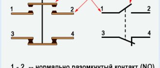
Starters are divided into two types with normal closed contacts and normal open contacts. From this you can understand how they work, the first turn off the voltage, and the second turn on; in order for power to be supplied, you need to use number two, and in order to suppress the first.
How switches, switches, sockets are depicted
There are no standards-approved images for some types of this equipment. So, dimmers (light regulators) and push-button switches remained without designation.
But all other types of switches have their own symbols in electrical diagrams. They come in open and hidden installations, respectively, there are also two groups of icons. The difference is the position of the line on the key image. In order to understand in the diagram what type of switch we are talking about, this must be remembered.
There are separate designations for two-key and three-key switches. In the documentation they are called “twin” and “twin”, respectively. There are differences for cases with different degrees of protection. In rooms with normal operating conditions, switches with IP20, maybe up to IP23, are installed. In wet rooms (bathroom, swimming pool) or outdoors, the degree of protection should be at least IP44. Their images differ in that the circles are filled in. So it's easy to distinguish them.
Read also: What can be used instead of borax
Symbols of switches in drawings and diagrams
There are separate images for the switches. These are switches that allow you to control turning the light on/off from two points (there are also three, but without standard images).
The same trend is observed in the designations of sockets and socket groups: there are single, double sockets, and there are groups of several pieces. Products for rooms with normal operating conditions (IP from 20 to 23) have an unpainted middle; for wet rooms with a housing of increased protection (IP44 and higher), the middle is tinted dark.
Symbols in electrical diagrams: sockets of different types of installation (open, hidden)
Having understood the logic of the designation and remembering some initial data (what is the difference between the symbolic image of an open and hidden installation socket, for example), after a while you will be able to confidently navigate the drawings and diagrams.
Where and why it is used
Electromagnetic starters and contactors are built into a power network that transports current; it can be direct or alternating voltage; the work is used on electromagnetic induction. The devices are equipped with a set of signal contacts, through which the connected devices are powered. Some perform an auxiliary function, while others perform a working function.
Electrical installations and electric motors are controlled by starters, but do not protect them in the event of a voltage drop, since the power contact opens, and the operation of the device to which the electromagnet is distributed is suspended and independent activation is excluded.
To put the equipment into operation, you need to use the “start” button. This ensures safety, since accidents may occur due to spontaneous activation.
The starter connection circuits may include relays with thermal action; they are designed to protect electric motors and other installations from long-term operation. There are single-pole and double-pole magnetic starters. They are triggered when exposed to a current overload of motors through which voltage passes.
Types of circuits in electrical
Drawing and reading different diagrams usually require different elements. There are many types of circuits, but in electrical engineering the following are usually used:
- Functional ones, which display the main components of the device, without detail. Outwardly it looks like a set of rectangles with connections between them. Gives a general idea of the functioning of the object.
The functional diagram shows the blocks and connections between them
Schematic diagram details the device
The installation room displays the location and route of cables/communication lines
There are many other types of electrical circuits, but they are not used in home practice. The exception is the route of cables passing through the site and the supply of electricity to the house. This type of document will definitely be needed and useful, but it is more of a plan than an outline.
Main characteristics
In order for the starter to work correctly, you need to follow certain installation rules, know the basics of devices with relays and select magnetic and reversing device circuits. Contactors and starters operate for a short time and devices with an open contact are most often used. Some have a signal circuit built into them and are designed for devices with consumption from 0.28 to 12 kilowatts, others for from 5 to 70 kilowatts and are capable of operating with a voltage distribution of 220 or 380 V.
Device options are divided into:
- open;
- protected;
- dust- and water-proof;
- dust-splash-proof form.
The PME starter contains a TRN “relay”, and the PAE model differs in the number of relays. If full voltage is supplied, the device's coils operate reliably. the main part of the devices has nodes:
- core;
- electromagnetic coil;
- anchor;
- frame;
- mechanical sensor;
- contact groups, central and additional.
The design may include an additional assembly consisting of a protective relay, an electrical fuse, an additional terminal set and a starting device.
The electromagnetic coil with turns is designed to transmit voltage up to 650 V. The coil is located in the heart, and most of the power is distributed to the power part of the springs. In the normal state, the contact is open and the springs are held in the upper position and hold the magnetic conductive sections.
There are starters that limit overvoltage; they are used for semiconductor systems. The coil begins operation of the alternating current system; the type of current and characteristic do not affect the operation of the installation.
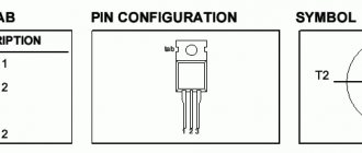
Contactors of the KM-103 series manufactured by DEKraft (Schneider Electric)
are used for switching electrical circuits (closing/opening contacts) and controlling the operation (start/stop) of asynchronous electric motors with a squirrel-cage rotor. Contactors are used to build automated control systems (for example, in automatic reserve connection systems), in industry, transport, etc.
Features of DEKraft modular contactors:
- Wide range of operating voltages of control coils (24-380V);
- Wide range of rated currents (9-630A);
- Availability of 2 additional contacts 1NO+1NC;
- Modern design and compact dimensions;
- DIN rail mounting;
- Large selection of accessories (thermal relays; block of additional contacts, including with a delay to turn on/off; mechanical interlocks, etc.);
- Affordable price and European quality.
Technical characteristics of KM-103 DEKraft (9-95A)
Rated current, A (at 380/400V AC-3)
Contactor coil voltage, V
24, 36, 110, 220, 380
Rated operating voltage Ue, V
Power of the switched electric motor in category AC-3 P, kW
Technical characteristics of KM-103 DEKraft (115-630A)
Rated current, A (at 380/400V AC-3)
Contactor coil voltage, V
Rated operating voltage Ue, V
Power of the switched electric motor in category AC-3 P, kW
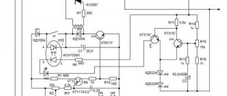
Electrical diagram:
5 starter connection diagrams, connection diagram via start and stop buttons
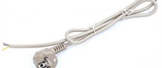
To connect the circuits, two “Start” and “Stop” keys are needed, each is produced in a separate case or in a single one, the operation of the device does not change from this and is called a push-button station.
If the buttons are located separately, then no questions arise, one contact is supplying power, the other is decreasing. And if the buttons are in the same case, then they each have 2 groups of contact lines, two for “Start” and two for “Stop”, each group has its own side. There is a compartment with a terminal for monitoring the current supply.
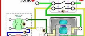
Connection diagrams for magnetic starters with 220 V coils - single-phase network and connection, simple option. 220 V is supplied to the upper and lower coils, which are located in the body of the device. A cord with a power input is connected to the wires; as soon as the plug is in the socket, the starter will begin operating. It is activated with any voltage, and is removed when the starter with contacts t1-t3 is activated.
Setting schemes using the “Start” and “Stop” buttons . The starter is used for electric motors; operation is convenient when there are “Start” and “Stop” buttons. For continuous operation of the devices, they are alternated by supplying phases to a magnetic coil. The starter operates only when the “Start” button is pressed, that is, it is not suitable for constant operation of the device. You can add self-retaining to the circuit; the work occurs with auxiliary contacts that can be installed on some types of devices.
Schemes for connecting 380 V asynchronous motors to 220 V starters - connecting three phases to contact wires and distributing the load along them. These are starters with a thermal relay; it functions to protect the motor from heating.
Reversible connection diagrams - used when it is necessary to ensure rotation of motors in opposite directions. The direction changes when the phase is transferred; the circuit contains two starters and a button block in which the “stop”, “forward” and “backward” keys are located.
The power circuits for connecting the contactor-phase are switched by redirection when the motors rotate, everything is controlled by the power circuit. When the contacts are triggered, a signal comes to the coil, for each of its own, only three phases, the engine runs in the left direction. Phase c is on the third winding, b is on b, and no changes occur in phase number one. In this case, the motor will move to the right.
The circuits are not complicated, but the reversible one requires double-sided protection so that there is no back-to-back switching. Divided into mechanical interlocking and contact protection.
Description
It is also more cost-effective, since there is no need to install contact attachments, where two additional contacts are sufficient.
A wide selection of contactors with different control coil voltages from 24V to 380V expands the functionality of their application.
Operating principle
When the rated voltage is applied to the coil, it draws in the core, and thereby closes a group of power and auxiliary contacts. When the voltage reaches below the release threshold level, the contacts open.
The following range of accessories is offered for contactors of the KM-103 series:
- Electrothermal relays RT-03 series;
- Contact attachments for side and front installation, series PK-03;
- Face-mounted time delay attachments, series PV-03;
- Locking mechanisms of the BM-03 series.
Scope of application
Contactors of the KM-103 are designed for starting and stopping asynchronous motors with a squirrel-cage rotor. They are used in conveyors, machine tools, compressors, pumps, elevators, escalators, heat guns and curtains, heating, ventilation and air conditioning control systems, etc., as well as for switching lighting networks.
In combination with an electrothermal overload relay they can also be used as a starter motor.
Letter designations on electrical circuits
To provide more complete information about the device, it is signed with an abbreviated letter designation. The number of letters is 2 or 3. Sometimes the letter designation turns into an alphanumeric one if you put the device serial number next to it.
Along with international ones, there are also Russian standards. They are listed in GOST 7624-55, but this document is declared invalid.
The article does not provide information about all symbols. Complete materials on graphic symbols can be found in GOST 2.709-89, 2.721-74, 2.755-87.
Download
If the topic interests you more deeply, I recommend that you read the literature listed on the page.
Here is one of the books listed there: • Lomonosov, V.Yu.; Polivanov, K.M.; Mikhailov, O.P. Electrical engineering. / Lomonosov, V.Yu.; Polivanov, K.M.; Mikhailov, O.P. Electrical engineering. One of the best books on the basics of electrical engineering. The presentation begins with the very basics: it explains what voltage, current and resistance are, provides instructions for calculating the simplest electrical circuits, and talks about the relationship and interdependence of electrical and magnetic phenomena. Explains what alternating current is and how an alternating current generator works. It describes what a capacitor is and what an inductor is, what their role is in alternating current circuits. It is explained what three-phase current is, how three-phase current generators are designed and how its transmission is organized. A separate chapter is devoted to semiconductor devices: it talks about semiconductor diodes, transistors and thyristors; on the use of semiconductor devices for rectifying alternating current and as semiconductor switches. The achievements of microelectronics are briefly described. The last third of the book is entirely devoted to electrical machines, units and equipment: chapter 10 deals with direct current machines (generators and motors); Chapter 11 is devoted to transformers; AC machines (single-phase and three-phase, synchronous and asynchronous) are described in detail in Chapter 12; switches, electromagnets and relays are described in Chapter 13; Chapter 14 deals with electrical diagramming. The last, chapter 15, is devoted to measurements in electrical engineering. This book is a great way to learn the basics of electrical engineering, to understand the fundamental principles of the operation of electrical machines and units., zip, 13.87 MB, downloaded: 2653 times./
Graphic images in electrical circuits
An electrical network drawing is a set of graphic elements that together form an inextricable system. In practice, this is a set of devices connected by wires.
Most of the symbols are graphic. Letters and numbers are used to symbolically designate individual elements, their denominations and distances between objects.
Main base images
Electrical circuits lead to devices and installations that are equipped with contacts that can break or connect these circuits.
The simplest example is an ordinary switch. All contacts are divided into make, break and switch contacts - these are the ones that are displayed in the diagrams.
The listed graphic images are mandatory when drawing up circuit diagrams and are usually understandable even to a novice electrician.
Single Line Diagram Symbolism
Drawings are also used to assemble electrical panels. They are usually a single line diagram indicating RCDs, circuit breakers, contactors and other protective equipment.
Some graphic symbols are similar to each other, so special attention is required when drawing up a diagram. For example, a contactor and a switch are designated the same, the difference is in a small element on the fixed contact.
Relay coils are designated by special symbols - in all images a rectangle is used as a basis.
To remember icons, associations or alphabetic clues are often used. For example, a motor drive is represented by a circle with the letter “M” inside it.
When drawing up a diagram, it should be borne in mind that quantity is also important for designating some symbols.
For example, if you need to indicate a 4-pin terminal block, then you should draw four crossed out circles in a row, and not one. Paired checkmarks when depicting sockets indicate the number of wires.
How are tires and wires depicted?
Linear graphics are used to designate buses, cables and wires - almost all symbols consist of straight lines.
Conductor connections are indicated by dots. If there is no mark at the junction of two lines, then this is a simple intersection.
Wires vary in type, purpose, load, and installation method. All this can also be shown schematically.
Additional characteristics facilitate the selection of materials and installation of the electrical network. In the future, thanks to the characteristics indicated in the diagram, one can judge the potential capabilities of the already installed electrical system.
Sockets and switches on diagrams
The designation of switches is divided into several groups - according to the degree of protection, installation method (hidden or open). There are separate switches for two directions. 2- and 3-gang switches are designated differently.
Some light source control devices do not have symbols - for example, push-button devices and dimmers.
Nowadays, to save energy in large rooms, pass-through switches are often installed, which are controlled from 2 or 3 points. You can also find corresponding icons for them.
Sockets, like switches, are divided into groups according to the degree of protection. Within groups, devices are divided by the number of poles and the presence of protection. To designate blocks, alphanumeric signatures are used, indicating the number and purpose of installations in one block.
When memorizing the designations of various electrical elements on the diagrams, each conventionally depicted device should be correlated with a real product.
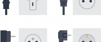
For example, popular types of sockets look like this:
In reality, electrical installation devices look like this:
Switches and sockets are one of the most “in demand” elements in circuits for home use, so they should be remembered first. Read more about the designation of such devices in drawings and diagrams in this article.
Designation of light sources
Separate symbols are also provided for different types of lamps and fixtures. Conveniently, there are special icons for LED and fluorescent light bulbs.
Standard images of various types of lamps are often used to draw up installation diagrams.
If you use the same symbols, you will have to include additional clarifications, but with standard symbols you can draw a diagram much faster.
Elements for drawing up electrical circuit diagrams
The basic symbols for circuit diagrams differ little, but in addition to them there are also special symbols for designating all kinds of radio elements: thyristors, resistors, diodes, etc.
There are separate symbols for radio devices, but they are usually not required when designing a home electrical network.
Lamps on diagrams
This section describes the symbols in the electrical circuits of various lamps and fixtures. Here the situation with the designations of the new element base is better: there are even signs for LED lamps and fixtures, compact fluorescent lamps (housekeepers). It’s also good that the images of lamps of different types differ significantly - it’s difficult to confuse them. For example, lamps with incandescent lamps are depicted in the form of a circle, with long linear fluorescent lamps - a long narrow rectangle. The difference in the image of a linear fluorescent lamp and an LED lamp is not very big - only dashes at the ends - but even here you can remember.
Image of lamps (incandescent, LED, halogen) and lamps (ceiling, built-in, wall-mounted) on diagrams
The standard even includes symbols in electrical diagrams for ceiling and pendant lamps (socket). They also have a rather unusual shape - circles of small diameter with dashes. In general, this section is easier to navigate than others.
Elements of electrical circuit diagrams
Schematic diagrams of devices contain a different element base. Communication lines, terminals, connectors, light bulbs are also depicted, but in addition, there is a large number of radio elements: resistors, capacitors, fuses, diodes, thyristors, LEDs. Most of the symbols in the electrical circuits of this element base are shown in the figures below.
Designation of electrical elements on device diagrams
Image of radioelements on diagrams
Rarer ones will have to be looked for separately. But most circuits contain these elements.
What types of electrical circuits might be useful?
Let's consider the design information from the point of view of an amateur electrician who wants to change the wiring in the house with his own hands or draw up a drawing for connecting the dacha to electrical communications.
First you need to understand what knowledge will be useful and what will not be needed. The first step is to become familiar with the types of electrical circuits.
All information about the types of circuits is presented in the new edition of GOST 2.702-2011, which is called “ESKD. Rules for the execution of electrical circuits."
This is a duplicate of an earlier document - GOST 2.701-2008, which talks in detail about the classification of circuits. There are 10 types in total, but in practice only one may be required - electric.
In addition to the type classification, there is also a standard one, which divides all drawing documents into structural, general, etc., with a total of 8 points.
The home craftsman will be interested in 3 types of diagrams: functional, schematic, installation.
Type #1 – functional diagram
The functional diagram does not contain details; it indicates the main blocks and assemblies. It gives a general idea of how the system works. For the electrical supply of a private home, it does not always make sense to draw up such drawings, since they are usually standard.
But when describing a complex electronic device or for equipping a workshop, studio or control room with electrical equipment, they can be useful.
Type #2 – circuit diagram
A schematic diagram, in contrast to a functional one, is a set of symbols, without knowledge of which it is difficult to understand the structure of the network as a whole. The drawing indicates all devices and connections between them.
If you need to reflect only power lines, it is enough to draw a linear diagram, but to depict all types of circuits with monitoring and control devices you will need a complete one.
Type #3 – wiring diagram
A wiring diagram is a document that is convenient to use when installing networks. Using it you can find out which devices should be connected, where exactly and how far from each other they are located.
The location of elements such as switches and sockets, lamps, and circuit breakers is indicated. You can set the values and lengths of the circuits directly in the diagram.
Requirements for all types of schematic documentation are set out in GOST 2.702-2011 , and this is what should be followed in the future when drawing up your own projects.
Here you can also find full links to other useful documents, which contain tables of graphic and letter symbols of various elements used in electrical circuits, as well as rules for their use.
Read also: DIY lever lift