A short circuit (and overload, as a special case) is the most dangerous emergency situation when operating a power supply. And the point is not only in the increased probability of failure of the elements of the power supply circuit. The thermal effect of a multiply increased current can lead to ignition of the conductor insulation and further development of the fire.
Powerful power supplies can also experience significant dynamic forces in current-carrying elements, which will result in displacement of the conductors and their mechanical damage. Therefore, short-circuit protection for power supplies is not a luxury, but an urgent necessity.
Relay protection circuit
Now let's move on to designs in which an electromagnetic relay is used as a control element. On the one hand, this somewhat reduces reliability - relay contacts can burn out at high currents. But on the other hand, such circuits are quite simple and can be used with power supplies designed for different output voltages - just select the right type of relay.
On one relay
The design is extremely simple, contains a minimum of parts and does not require adjustment. The only thing, as noted above, is to select the relay based on the operating voltage and the corresponding power.
The device works as follows. In the initial position, LED2 is lit, the load is de-energized. When you press button S2, power is supplied to the coil of relay K1 and it is activated, connecting the load to the power source and simultaneously turning off the button and LED2. In this case, capacitor C1 serves to delay the switching off of the relay while its contacts are switched. Together with the load, power through diode D1 is supplied to winding K1 and it becomes self-blocking. The button can be released. LED1 will light up, indicating that the load is powered.
When there is a short circuit, the voltage in the power circuit of the relay drops and it is released, disconnecting the load and reconnecting the button. LED1 goes out, LED2 lights up. In order to restart the node, you must remove the overload and press the S1 button again.
Important! With the relay indicated on the diagram, the device can be used with a 12-volt power supply or charger. If the source voltage is different, it is necessary to select a relay that is triggered by this voltage.
On a relay and a unijunction transistor
This circuit is somewhat more complicated than the previous one, but it allows you to adjust the protection operation current.
As long as the current through the load does not exceed a certain value, the composite transistor T1, T2 is closed. As the current increases, the voltage drop across the current-measuring resistor R1 causes T1 and T2 to open, and after them, relay K1 to operate. The relay disconnects the load and connects resistor R4 to the positive bus, which prevents the relay from turning off.
To return the structure to its original state, just press button S2. The relay will turn off and the load will receive power again. If the cause of the short circuit is not eliminated, then after releasing the button the protection will work again. The magnitude of the operating current can be adjusted using variable resistor P1.
Important! It is not recommended to hold the S2 button for a long time. If the cause of the short circuit is not eliminated, the power supply will be overloaded and burn out, since the protection unit will be forcibly turned off.
In the block you can use KT805 transistors with any letter, 2SC2562, 2N3054 (T2) and any low-power silicon transistors of the pnp structure. The relay response voltage should be slightly lower than the power source voltage. LED1 “Overload” – any indicator.
Option 3
This is a particularly simple circuit, which can hardly even be called a circuit, since it uses only 2 components. This is a powerful diode and fuse. This option is quite viable and is even used on an industrial scale.
Power from the charger is supplied to the battery through the fuse. The fuse is selected based on the maximum charging current. For example, if the current is 10 A, then a 12-15 A fuse is needed.
The diode is connected in parallel and is closed during normal operation. But if the polarity is reversed, the diode will open and a short circuit will occur.
And the fuse is the weak link in this circuit, which will burn out at the same moment. After this you will have to change it.
The diode should be selected according to the datasheet based on the fact that its maximum short-term current was several times greater than the fuse combustion current.
This scheme does not provide 100% protection, since there have been cases when the charger burned out faster than the fuse.
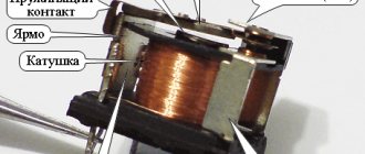
Concept of an asynchronous electric motor
As can be seen in the photo of an asynchronous motor, such a unit is an electric machine, the purpose of which is to convert electricity into mechanical energy. In other words, such equipment, consuming electric current, produces torque. It is this that allows you to rotate many units.
The name "asynchronous" means "non-simultaneous". If you study the description of asynchronous motors, you will notice that in such devices the rotor rotates at a lower frequency than the electromagnetic field of the stator.
This lag or, as it is also called, slip can be calculated using the following formula:
S = (n1 - n2)/ n1 - 100%, where
n1 – frequency of the stator electromagnetic field;
n2 – shaft rotation frequency.
Why might a breakdown occur?
During the constant operation of an electric motor, a lot of unforeseen circumstances can occur that will disable it. And in order to be prepared for all these difficulties, you need to know them and be able to prevent them.
Here's what can damage an electric motor:
- Low voltage in the electrical network.
- The voltage is too high for which the motor is not designed.
- Poor power supply and poor signal quality.
- Constant jumps in the system.
- Incorrect installation or non-standard operating rules of the electric motor.
- Increased temperature in a running engine and frequent overheating.
- Poor cooling of equipment.
- Increased temperature in the space around the engine.
- Low atmospheric pressure due to engine operation in mountainous areas.
- Problems with the engine fluid.
- Frequent turning on and off of the engine.
- Increased inertial load on the engine. This indicator is different for each model.
- Overheating due to blocked rotor or phase loss.
We will consider the simplest and most popular device for this further.
Operating principle of a thermistor
The critical values of the resistance/temperature relationship for motor protection sensors are defined in DIN 44081/DIN 44082.
The DIN curve shows the resistance in thermistor sensors as a function of temperature.
Compared to PTO, thermistors have the following advantages:
• Faster response due to lower volume and weight
• Better contact with the motor winding
• Sensors are installed on each phase
• Provide protection when the rotor is blocked
Literature
- https://www.bourns.com/data/global/pdfs/bourns_tbu_short_form.pdf
- https://www.bourns.com/ProductLine.aspx?name=tbu
- https://www.bourns.com/data/global/pdfs/CP_cell_base_station_appnote.pdf.
Obtaining technical information, ordering samples, ordering and delivery.
Full diagnostic inspection of the engine
In order to inspect the stator and other central elements of the electric motor, special goats are used, equipped with two rollers in the upper part. The latter simplify the rotation of parts.
Self-repair of the motor should begin with a thorough study of all technical documentation. Next, the degree of wear of the bearings is determined, and other defects are detected and eliminated.
Technical work is carried out using a set of special keys, an ordinary tester and lifting mechanisms. The main thing is not to forget to disconnect the motor from the network. All components are cleaned of dust layers using brushes and blown with compressed air. In the future, it is advisable to put small parts and all their fastenings in a separate box to avoid loss.
The electric motor rotor is disassembled taking into account the following recommendations. As soon as the shield is separated from the motor body, it is moved along the shaft, being careful not to damage the insulation of the windings. For these purposes, high-density cardboard is used, placing it between the stator and rotor, and subsequently laying parts on it.
Springs and bearings are also removed from the shaft. The short-circuited winding and core are dismantled. The main requirement when removing the rotor is careful movement along the axis.
When checking fans, pay attention to the integrity of the blades and the reliability of their fastening. The procedure is done using a hammer
Defective parts are replaced. The balancing must not be disturbed, so before inspection it is necessary to make a note on the rotor so that each element falls into place when assembled.
Bottom line
From an efficiency point of view, the first scheme is better than the others. But from the point of view of versatility and speed of response, the best option is scheme 2. Well, the third option is often used on an industrial scale. This type of protection can be seen, for example, on any car radio.
All circuits, except the last one, have a self-healing function, that is, operation will be restored as soon as the short circuit is removed or the polarity of the battery connection is changed.
Author: Eduard Orlov –
Attached files:
How to choose a softstarter
The question of how to choose a soft starter arises quite often, because the mechanism is selected for a specific electric motor and power source.
In order not to make mistakes with parameters and capabilities, it is recommended to pay attention to the following indicators:
- The maximum current produced by the motor at the highest loads;
- The largest number of starts in one hour;
- Rated voltage on the supply system;
- Ability to control and limit the generated current;
- Possibility of bypassing - disconnecting the power supply from the circuit to prevent overheating and fire;
- Number of phases (two – more compact and cheaper, three – more reliable and durable for frequent starts);
- Digital or analog control.
The main thing is that the requirements put forward for the softstarter comply with the criteria, operating conditions, engine power and nominal network values. Pivot tables and calculation algorithms offered by many suppliers will also help in the selection for a more convenient and high-quality search for a suitable device.
Designs and types of permanent magnet synchronous motor
A permanent magnet synchronous motor, like any rotating electric motor, consists of a rotor and a stator. The stator is the stationary part, the rotor is the rotating part.
Synchronous electric motor with built-in permanent magnets
Usually the rotor is located inside the stator of the electric motor; there are also designs with an external rotor - inverted type electric motors.
Permanent magnet synchronous motor designs: left - standard, right-facing.
Rotor
consists of permanent magnets. Materials with high coercivity are used as permanent magnets.
- According to the rotor design, synchronous motors are divided into:
- electric motors with salient poles;
- electric motors with implicit poles.
An electric motor with implicit poles has equal inductance along the longitudinal and transverse axes Ld = Lq, while for an electric motor with salient poles the transverse inductance is not equal to the longitudinal one Lq ≠ Ld.
Cross section of rotors with different Ld/Lq ratios. Magnets are shown in black. Figure e, f show axially laminated rotors, figure c and h show rotors with barriers.
- Also, according to the rotor design, PMSMs are divided into:
- synchronous motor with surface
permanent magnets (SPMSM - surface permanent magnet synchronous motor); - synchronous motor with built-in
(incorporated) magnets (IPMSM - interior permanent magnet synchronous motor).
Rotor of a synchronous motor with surface mounted permanent magnets
Synchronous motor rotor with built-in magnets
Stator
consists of a body and a core with a winding. The most common designs are with two- and three-phase windings.
- Depending on the stator design, a permanent magnet synchronous motor is:
- with distributed winding;
- with concentrated winding.
Electric motor stator with distributed winding
Concentrated winding motor stator
Distributed
they call a winding in which the number of slots per pole and phase Q = 2, 3,...., k.
Focused
they call a winding in which the number of slots per pole and phase Q = 1. In this case, the slots are located evenly around the circumference of the stator. The two coils that form the winding can be connected either in series or in parallel. The main disadvantage of such windings is the inability to influence the shape of the EMF curve.
Three-phase distributed winding diagram
Three-phase concentrated winding diagram
Back EMF form
the electric motor can be: trapezoidal; sinusoidal.
The shape of the EMF curve in the conductor is determined by the distribution curve of the magnetic induction in the gap around the circumference of the stator.
It is known that the magnetic induction in the gap under the pronounced pole of the rotor has a trapezoidal shape. The EMF induced in the conductor has the same shape. If it is necessary to create a sinusoidal EMF, then the pole pieces are given a shape in which the induction distribution curve would be close to sinusoidal. This is facilitated by the bevels of the rotor pole pieces.
INA226 Datasheet PDF
This ADC has high performance and high conversion accuracy. Devices using this module have already been described on the site. For example, “Digital ammeter and voltmeter for INA226 power supply.” There is also an article on the site for people just starting to take their first steps in programming microcontrollers in Assembly language. The article is devoted to the program for interaction of PIC controllers with the INA226 microcircuit - “Program for interaction of INA226 with the PIC microcontroller.”
The display module is developed on the basis of two drivers of TM1637 microcircuits.
Negative Hot Plug Controllers
-48 V is traditionally used to power telecommunications systems. For example, these are ATC systems, optical networks, base stations and blade servers (high-density servers). Initially, the supply voltage was provided by powerful lead acid batteries, so a voltage of -48 V was chosen as high enough to transmit power and signals over long distances and at the same time low enough to ensure safe operation. The common wire in such systems is the positive electrode. Hot-plug controllers for modules in telecommunications equipment racks provide safe connection and disconnection of modules without the risk of disrupting the operation of adjacent operating modules. First of all, the inrush current is limited, which prevents the destruction of the power contacts of the connectors during connection, as well as voltage dips or surges. The TI range includes a wide range of Hotswap controllers that operate with negative polarity voltages up to -80 V. The protective elements of the controllers implement various functions and protection scenarios: with a latch or with auto-recovery after a power failure. Table 6 presents the main parameters of TI Hotswap controllers.
Table 6. Microcircuits of hot-plug controllers for negative voltage
| Name | Operating voltage range, V | Control and protection signals | Error handling |
| TPS2399 | -80…-36 | Enable; PowerGood | Auto repeat |
| LM5068 | -90…10 | Overvoltage; Undervoltage; PowerGood | Auto repeat; latch |
| TPS2398 | -80…-36 | Enable; PowerGood | Latch |
| LM5067 | -80…-9 | Overvoltage; Undervoltage; PowerGood | Auto repeat; latch |
| TPS2394 | -80…-12 | Fault; PowerGood; Overvoltage; Undervoltage | Auto repeat |
| TPS2350 | -80…-12 | Fault; PowerGood; Overvoltage; Undervoltage | Auto repeat |