Kinds
Secondary circuits come in several varieties. So, these include voltage and current circuits. They are distinguished by the presence of devices for measuring current, power, and voltage.
There is also an operational type. It facilitates the transmission of current to the main actuators. Secondary circuits of this type are represented by electromagnets, contactors, automated switches, fuses, keys, and so on.
The current circuit that comes from the CT for measurements is most often used to power:
- Instruments that display and measure ammeters, wattmeters, varmeters, and so on.
- Protective relay systems: remote, against short circuits, against switch failures and others.
- Devices for regulating power flows, emergency automation.
- A number of devices included in the alarm or blocking system.
In addition, a current circuit is used when there is a need to power devices for converting alternating current into direct current, which are used as sources of operational current.
You are master
3.4.1. This chapter of the Rules applies to secondary circuits (control, alarm, monitoring, automation and relay protection circuits) of electrical installations.
3.4.2. The operating voltage of the secondary circuits of the connection, which is not connected to other connections and the equipment of which is located separately from the equipment of other connections, should not be higher than 1 kV. In all other cases, the operating voltage of the secondary circuits should be no higher than 500 V.
The design of the connected devices must comply with environmental conditions and safety requirements.
3.4.3. In power plants and substations, control cables with semi-solid aluminum conductors should be used for secondary circuits. Control cables with copper conductors should only be used in secondary circuits:
1) power plants with generators with a capacity of more than 100 MW; at the same time, at power plants for secondary switching and lighting of chemical water treatment facilities, wastewater treatment, utility and auxiliary structures, mechanical workshops and start-up boiler houses, control cables with aluminum conductors should be used;
2) switchgear and substations with a higher voltage of 330 kV and above, as well as switchyards and substations included in intersystem transit power transmission lines;
3) differential busbar protection and failure backup devices for 110 – 220 kV circuit breakers, as well as system emergency automation equipment;
4) technological protection of thermal power plants;
5) with an operating voltage not higher than 60 V with a diameter of cable cores and wires up to 1 mm (see also 3.4.4);
6) power plants and substations located in explosive zones of classes B-I and B-Ia.
In industrial plants, control cables with aluminum-copper or semi-solid aluminum conductors should be used for secondary circuits. Control cables with copper conductors should be used only in secondary circuits located in explosive zones of classes B-I and B-Ia, in secondary circuits of mechanisms of blast furnace and converter shops, the main line of crimping and continuous high-performance rolling mills, electrical receivers of special group I category, and also in secondary circuits with an operating voltage not higher than 60 V with a diameter of cable cores and wires up to 1 mm (see also 3.4.4).
3.4.4. According to the condition of mechanical strength:
1) the cores of control cables for screw connection to the terminals of panels and devices must have a cross-section of at least 1.5 square meters. mm (and when using special clamps - at least 1.0 sq. mm) for copper and 2.5 sq. mm. mm for aluminum; for current circuits - 2.5 sq. mm for copper and 4 sq. mm for aluminum; for non-critical secondary circuits, for control and signaling circuits, screw connection of cables with copper conductors with a cross-section of 1 square meter is allowed. mm;
2) in circuits with an operating voltage of 100 V and above, the cross-section of the copper conductors of the cables connected by soldering must be at least 0.5 square meters. mm;
3) in circuits with an operating voltage of 60 V and below, the diameter of the copper cores of the cables connected by soldering must be at least 0.5 mm. In communication devices, telemechanics and the like, linear circuits should be connected to screw terminals.
The connection of single-wire conductors (by screw or soldering) is allowed only to fixed elements of the equipment. The connection of cores to movable or removable elements of equipment (plug-in connectors, removable blocks, etc.), as well as to panels and devices subject to vibration, should be made with flexible (stranded) cores.
3.4.5. The cross-section of the cores of cables and wires must meet the requirements for their protection against short-circuit without time delay, permissible long-term currents in accordance with Chapter. 1.3, thermal resistance (for circuits coming from current transformers), as well as ensure the operation of devices in a given accuracy class. In this case, the following conditions must be met:
1. Current transformers together with electrical circuits must operate in the accuracy class:
for settlement meters - according to Ch. 1.5;
for power measuring transducers used to input information into computing devices - according to Ch. 1.5, as for technical metering meters;
for panel devices and current and power measuring transducers used for all types of measurements - not lower than accuracy class 3;
for protection, usually within a 10% error (see also Chapter 3.2).
2. For voltage circuits, the voltage loss from the voltage transformer, provided that all protections and devices are turned on, should be:
to metering meters and power measuring converters used to enter information into computing devices - no more than 0.5%;
to the estimated meters of intersystem power transmission lines - no more than 0.25%;
to technical metering meters - no more than 1.5%;
to panel devices and power sensors used for all types of measurements - no more than 1.5%;
to protection and automation panels - no more than 3% (see also Chapter 3.2).
When the specified loads are powered together via common conductors, their cross-section must be selected according to the minimum permissible voltage loss standards.
3. For operational current circuits, the voltage loss from the power source should be:
to the device panel or to control electromagnets that do not have boost - no more than 10% at the highest load current;
to control electromagnets that have a threefold or greater boost - no more than 25% at the boost current value.
4. For voltage circuits of AVR devices, the voltage loss from the voltage transformer to the measuring element should be no more than 1%.
3.4.6. In one control cable it is possible to combine control, measurement, protection and signaling circuits of direct and alternating current, as well as power circuits feeding low-power electrical receivers (for example, electric motors of valves).
To avoid an increase in the inductive reactance of the cable cores, the wiring of the secondary circuits of the current and voltage transformers must be done so that the sum of the currents of these circuits in each cable is equal to zero in any mode.
It is allowed to use common cables for circuits of different connections, with the exception of mutually redundant ones.
3.4.7. Cables should generally be connected to clamp assemblies. Connecting two copper wires of a cable under one screw is not recommended, and two aluminum wires are not allowed.
Cables may be connected directly to the terminals of instrument transformers or individual devices.
The design of the clamps must match the material and cross-section of the cable cores.
3.4.8. Connecting control cables in order to increase their length is permitted if the length of the route exceeds the construction length of the cable. The connection of cables with a metal sheath should be carried out with the installation of sealed couplings.
Cables with a non-metallic sheath or with aluminum conductors should be connected on intermediate rows of clamps or using special couplings designed for this type of cable.
3.4.9. Secondary circuit cables, cable cores and wires connected to terminal assemblies or devices must be marked.
3.4.10. Types of wires and cables for secondary circuits, methods of their installation and protection should be selected taking into account the requirements of Chapter. 2.1 – 2.3 and 3.1 to the extent that they are not changed by this chapter. When laying wires and cables over hot surfaces or in places where the insulation may be exposed to oils and other aggressive environments, special wires and cables should be used (see Chapter 2.1).
Wires and cable cores that have non-light-resistant insulation must be protected from exposure to light.
3.4.11. Cables of secondary circuits of voltage transformers of 110 kV and above, laid from the voltage transformer to the switchboard, must have a metal sheath or armor grounded on both sides. Cables in the circuits of the main and additional windings of one voltage transformer of 110 kV and higher along the entire length of the route should be laid side by side. For circuits of devices and devices that are sensitive to interference from other devices or nearby circuits, shielded wires must be used, as well as control cables with a common shield or cables with shielded conductors.
3.4.12. Installation of direct and alternating current circuits within switchboard devices (panels, consoles, cabinets, boxes, etc.), as well as internal connection diagrams of drives of switches, disconnectors and other devices, according to the conditions of mechanical strength, must be made with wires or cables with copper conductors cross-section not less than:
for single-wire conductors connected with screw terminals, 1.5 sq. mm;
for single-wire conductors connected by soldering, 0.5 sq. mm;
for stranded conductors connected by soldering or screwing using special lugs, 0.35 sq. mm; in technically justified cases, it is allowed to use wires with stranded copper conductors, connected by soldering, with a cross-section of less than 0.35 square meters. mm, but not less than 0.2 sq. mm;
for cores connected by soldering in circuits with a voltage not exceeding 60 V (control panels and consoles, telemechanics devices, etc.) – 0.197 sq. mm (diameter – not less than 0.5 mm).
The connection of single-wire conductors (by screw or soldering) is allowed only to fixed elements of the equipment. The connection of cores to movable or removable elements of equipment (detachable connectors, removable blocks, etc.) should be done with flexible (stranded) cores.
Mechanical loads on the places where wires are soldered are not allowed.
For transitions to device doors, stranded wires with a cross-section of at least 0.5 square meters must be used. mm; It is also allowed to use wires with single-wire conductors with a cross-section of at least 1.5 square meters. mm, provided that the wiring harness works only in torsion.
The cross-section of wires on switchboard devices and other factory-made products is determined by the requirements for their protection against short-circuits without time delay, permissible current loads in accordance with Chapter. 1.3, and for circuits coming from current transformers, in addition, thermal resistance. For installation, wires and cables with insulation that does not support combustion should be used.
The use of wires and cables with aluminum conductors for internal installation of switchboard devices is not allowed.
3.4.13. Connections of devices to each other within the same panel should, as a rule, be made directly without connecting the connecting wires to intermediate terminals.
The terminals or test blocks must contain circuits in which testing and checking apparatus and instruments are required to be included. It is also recommended to output circuits to a number of terminals, the switching of which is required to change the operating mode of the device.
3.4.14. Intermediate clamps should only be installed where:
the wire goes into the cable;
circuits of the same name are combined (assembly of terminals for trip circuits, voltage circuits, etc.);
required to include portable test and measuring apparatus if test blocks or similar devices are not available;
several cables become one cable or the circuits of different cables are redistributed (see also 3.4.8).
3.4.15. Terminals belonging to different connections or devices must be separated into separate terminal assemblies.
On the rows of terminals there should not be any clamps in close proximity to one another, the accidental connection of which could cause the connection to be turned on or off or a short circuit in the operational current circuits or in the excitation circuits.
When placing equipment related to different types of protection or other devices of the same connection on a panel (in a cabinet), the supply of power from the operational current poles through the terminal assemblies, as well as the wiring of these circuits throughout the panel, must be carried out independently for each type of protection or device. If linings are not provided in the trip circuits from individual protection sets, then the connection of these circuits to the output protection relay or circuit breaker trip circuits should be carried out through separate terminals of the terminal assembly; in this case, connections along the panel of these circuits should be made independently for each type of protection.
3.4.16. To carry out operational checks and tests in protection and automation circuits, test blocks or measuring clamps should be provided, providing (except for the cases specified in 3.4.7) without disconnecting wires and cables, disconnection from the source of operational current, voltage and current transformers with the possibility of preliminary short-circuiting current circuits; connection of testing devices for checking and adjusting devices.
Relay protection and automation devices that are periodically taken out of operation due to the requirements of the network mode, selectivity conditions, and other reasons must have special devices for taking them out of operation by operating personnel.
3.4.17. Clamp assemblies, auxiliary contacts of switches and disconnectors and devices must be installed, and grounding conductors mounted in such a way that accessibility and safety of servicing the assemblies and devices of secondary circuits is ensured without removing the voltage from primary circuits with voltages above 1 kV.
3.4.18. The insulation of equipment used in secondary circuits must comply with the standards determined by the operating voltage of the source (or isolation transformer) feeding these circuits.
Insulation monitoring of operational direct and alternating current circuits should be provided at each independent source (including isolation transformers) that is not grounded.
The insulation monitoring device must provide a signal when the insulation drops below a set value, and at direct current, it must also measure the value of the insulation resistance of the poles. Insulation monitoring may not be performed when the operating current network is unbranched.
3.4.19. Operating current supply to the secondary circuits of each connection should be carried out through separate fuses or circuit breakers (the latter is preferable).
Operating current supply to the relay protection and switch control circuits of each connection must be provided, as a rule, through separate circuit breakers or fuses not connected to other circuits (alarm, electromagnetic blocking, etc.). Shared power supply of control circuits and position signaling lamps of the controlled device is allowed.
For connections of 220 kV and above, as well as for generators (units) with a capacity of 60 MW and more, separate power supply with operating current (from different fuses, circuit breakers) must be provided for the main and backup protections.
When connecting circuit breakers and fuses in series, the latter must be installed in front of the circuit breakers (on the power source side).
3.4.20. Relay protection, automation and control devices for critical elements must have constant monitoring of the state of the operating current supply circuits. Monitoring can be carried out using separate relays or lamps or using devices provided to monitor the health of the circuit of subsequent operation of switching devices with remote control.
For less critical devices, power control can be carried out by sending a signal about the off position of the circuit breaker in the operating current circuit.
Monitoring the health of the subsequent operation circuit must be carried out in the presence of an auxiliary contact of the switching device. In this case, monitoring the serviceability of the shutdown circuit must be carried out in all cases, and monitoring the serviceability of the switching circuit must be carried out on switches of critical elements, short circuiters and on devices switched on under the influence of automatic transfer transfer devices (ATS) or telecontrol.
If the parameters of the drive enable circuits do not provide the ability to monitor the serviceability of this circuit, monitoring is not performed.
3.4.21. In electrical installations, as a rule, an automatic signal must be provided about a violation of the normal operating mode and about the occurrence of any malfunctions.
Checking the serviceability of this alarm system should include periodic testing.
In electrical installations operating without constant personnel duty, a signal must be provided to the location of the personnel.
3.4.22. Operating current circuits in which false operation of various devices is possible from overvoltage during the operation of switching electromagnets or other devices, as well as during ground faults, must be protected.
3.4.23. Grounding in the secondary circuits of current transformers should be provided at one point on the terminal assembly closest to the current transformers or on the terminals of the current transformers.
For protections combining several sets of current transformers, grounding must also be provided at one point; in this case, grounding is allowed through a breakdown fuse with a breakdown voltage of no higher than 1 kV with a shunt resistance of 100 Ohms to drain the static charge.
The secondary windings of intermediate isolating current transformers may not be grounded.
3.4.24. The secondary windings of the voltage transformer must be grounded by connecting the neutral point or one of the ends of the winding to a grounding device.
Grounding of the secondary windings of a voltage transformer must be carried out, as a rule, at the terminal assembly closest to the voltage transformer or at the terminals of the voltage transformer.
It is allowed to combine the grounded secondary circuits of several voltage transformers of one switchgear with a common grounding busbar. If the specified busbars belong to different switchgears and are located in different rooms (for example, relay boards of switchgears of different voltages), then these busbars, as a rule, should not be connected to each other.
For voltage transformers used as sources of operational alternating current, if working grounding of one of the poles of the operational current network is not provided, protective grounding of the secondary windings of the voltage transformers must be carried out through a breakdown fuse.
3.4.25. Voltage transformers must be protected from short circuits in secondary circuits by automatic switches. Circuit breakers should be installed in all ungrounded conductors after assembling the terminals, with the exception of the zero-sequence circuit (open delta) of voltage transformers in networks with high ground fault currents.
For unbranched voltage circuits, circuit breakers may not be installed.
In the secondary circuits of the voltage transformer, it must be possible to create a visible break (switches, detachable connectors, etc.).
The installation of devices that can create a break in the conductors between the voltage transformer and the grounding point of its secondary circuits is not allowed.
3.4.26. On voltage transformers installed in networks with low ground fault currents without capacitive current compensation (for example, on the generator voltage of a generator-transformer unit, on the auxiliary voltage of power plants and substations), if necessary, protection against overvoltage should be provided in the event of spontaneous neutral displacements. Protection can be achieved by including active resistances in an open delta circuit.
3.4.27. In the secondary circuits of linear voltage transformers of 220 kV and above, redundancy from another voltage transformer must be provided.
It is allowed to perform mutual redundancy between linear voltage transformers if they have sufficient power for the secondary load.
3.4.28. Voltage transformers must have monitoring of the health of voltage circuits.
Relay protection, the circuits of which are powered by voltage transformers, must be equipped with the devices specified in 3.2.8.
Regardless of the presence or absence of the protection circuits of the specified devices, the following signals must be provided:
when disconnecting circuit breakers - using their auxiliary contacts;
in case of malfunctions of relay repeaters of bus disconnectors - with the help of monitoring devices for open control circuits and relay repeaters;
for voltage transformers, in the circuit of the high voltage windings of which fuses are installed, in case of violation of the integrity of the fuses - with the help of central devices.
3.4.29. In places subject to shocks and vibrations, measures must be taken against disruption of contact connections of wires, false operation of relays, as well as against premature wear of devices and devices.
3.4.30. The panels must have inscriptions on the serviceable sides indicating the connections to which the panel belongs, its purpose, the serial number of the panel in the panel, and the equipment installed on the panels must have inscriptions or markings according to the diagrams.
How are they built
Installation of secondary circuits is carried out taking into account a number of rules. Thus, each device can be connected to 1 or several current sources. This is determined taking into account the power consumption, the required accuracy, and length.
If we are talking about a multi-winding transformer, the secondary circuit is an independent source of current. All secondary devices that are connected to the CT of one phase are connected to the secondary winding in a certain order. The devices and connecting circuits must form a closed system. You cannot open the secondary circuit of a current transformer if there is current in the primary. Therefore, circuit breakers and fuses are never installed in it.
Preparation and laying of wires.
All secondary devices (panels and remote control panels, protection, alarms and automation, cabinets, assemblies) are supplied by the manufacturers fully assembled, including installation of secondary circuits with devices and instruments that have undergone inspection, adjustment and testing.
Finished elements of electrical wiring of secondary circuits within one device (panel, cabinet, etc.) end with sets of clamps intended for connecting cores of connecting wires and control cables to them. Wiring of secondary circuits is an important part of the electrical installation, therefore, during installation, they are subject to high demands on the quality of work, as well as on the reliability of all contact connections.
Secondary circuits within switchboard panels, relay cabinets, switchgear chambers are made with insulated wires with aluminum or copper conductors (permitted by the PUE in some cases).
According to the conditions of mechanical strength, aluminum conductors of cables and wires connected to the terminals of devices and devices must have a cross-section of at least 2.5 mm2, copper - at least 1.5 mm2. For non-critical secondary circuits in electrical installations with voltages up to 1000 V, control and signaling circuits of electrical installations of industrial enterprises, it is allowed to connect copper conductors with a cross-section of 1 mm2 to the terminals of devices and devices.
In circuits with voltages up to 60 V, the diameter of the copper cores of the cables connected by soldering must be at least 0.5 mm. External connections of the secondary circuits of panels, cabinets, chambers with each other and with blocking, measuring and signaling devices of electrical equipment are carried out with control cables. Less commonly, these connections are made with insulated wires, protected from mechanical damage by steel or other pipes, boxes, trays, etc.
Recently, for the installation of electrical wiring of secondary circuits on switchboards and consoles, new aluminum-copper AMPV wires with a cross-section of 1.5-10 mm2 with polyvinyl chloride insulation, an aluminum core with a copper sheath, have been produced. It is allowed to use them temporarily to test wires under operating conditions.
Installation of secondary circuits, as well as other circuits and devices, begins with a review of design drawings and diagrams and their compliance with the requirements of industrial installation. Project documentation contains: explanatory note; diagrams of electrical connections and connections; schematic electrical diagrams of external and internal connections of electrical devices; general view drawings of boards, panels, cells; working drawings of cable distribution and cable magazine; lists of inscriptions and lists of elements indicating positional and letter designations of names, types, technical data, numbers of cabinets, panels, consoles; custom specifications; lists of MEZ products and drawings of non-standard components and structures.
When preparing for installation in the MEZ, they assemble assemblies and packages of wires, manufacture and complete supporting and fastening structures, products and parts for laying wires and cables of secondary circuits. In the process of installing secondary circuits, different methods of laying packages and wire flows are used: with rigid fastening to the panel, freely hanging packages without attachment to the base, on strings, in boxes, on trays, perforated profiles, tracks and “directly”.
Rice. 1. Preparing a stream of wires using a universal template (a) and bending them onto a plane using a wooden plate (b) or an aluminum bracket (c)
Packages and streams of wires are prepared and assembled in the MEZ according to measurement sketches using templates. In Fig. 1, a-c show the preparation of a stream of wires on a wooden plate using universal templates, their packaging and bending. Using such templates and rearranging the studs, you can prepare threads and packages of wires according to various schemes. To manufacture several identical flows or jumpers according to the same scheme, simple templates are used, made of electrical cardboard, plywood or other sheet material and representing a mock-up of part or the entire mounted panel.
When forming wire flows, comply with the requirements of the instructions: maintain a bending radius for flexible single- and multi-wire wires of at least five diameters, avoid crossing wires during branches, and if necessary, cross them at the exit from the main flow or directly at the device; perform turns equally and at right angles; They bandage wires in streams in straight sections with a pitch of 150-200 mm, as well as in all places where wires exit.
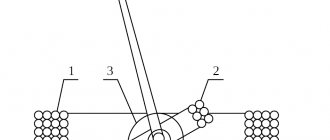
Let's look at the most commonly used methods of laying wires. The laying of wires in freely hanging packages (Fig. 2, a) is carried out without fastening to the panel; the packages are suspended on the connecting terminals of devices and devices. This method is used for this panel with a short length of wires and a vertical arrangement of rows of stacked clamps, which greatly simplifies installation and reduces the complexity of installation. However, connecting the control cable cores in this case becomes somewhat more complicated. Wires of freely hanging packages are laid at a distance of at least 10 mm from the surface.
Rice. 2. Laying wires of secondary circuits: a - freely hanging packages, b - on a string, c - “directly”; 1 — package of wires, 2 — insulating gasket, 3 — buckle strip, 4 — device output, 5 — panel, 6 — device
When mounting on a string (Fig. 2, b), the wires of the secondary circuits are pre-connected into one common bundle. A string is placed in the middle of the bundle, which is a straightened steel wire with a diameter of 5 mm with a polyvinyl chloride tube put on it. The wire has a thread at one end. A bandage of perforated polyvinyl chloride tape, secured with a polystyrene button or buckle strip, is applied to the bundle of wires every 175–200 mm (for horizontal laying blanks) and every 250–300 mm (for vertical laying blanks). The bundles of wire prepared in this way are transferred to the panel and attached to brackets pre-welded to the panel. Tensioning the wire into a string and aligning the bundle is done by screwing a nut on one end of the wire, while its other end is bent on the bracket. The wire cores are connected in the usual way. The string can also be made of a 2X20 mm steel strip with PVC tape wound along its entire length.
Laying wires with rigid fastening to the panel is rarely used. To fasten the wire flows, thin tin strips-buckles are used, welded to the steel sheets of the panels by spot electric welding. When marking on the panels, strips are welded at two points, the length of which should be slightly greater than twice the width of the flow of wires being fixed.
When laying wires on the panels, strips of electrical cardboard or varnished cloth are glued along the flow path. The wires are additionally insulated from the metal strips with varnished cloth or electrical cardboard. Having laid the thread, the strips are bent towards its center, the ends are threaded into the holes of the buckles, pulled together with pliers and slightly bent in different directions. Excess strips are cut off with scissors, the remaining ends are bent as far as possible with a wooden mandrel, hitting it with a light hammer.
The distance between the points of attachment of the wire flow to the panel in straight sections is taken to be 175-200 mm horizontally and 250-300 mm vertically. Wires are connected only in type-set terminals or at the terminals of devices and devices (connecting wires between terminals is not allowed). Within the same panel, the devices are connected to each other without connecting the connecting wires to the terminals. It is not allowed to connect copper and aluminum wires in one clamp with one screw. Connections between the terminals of the devices are made with permanent jumpers that sequentially go around the screws of the connected terminals using limiting star washers.
Laying wires “directly” (Fig. 2, c) reduces the complexity of installation and is used for panels on which devices made with front connection are installed. With this method of laying the wires, they do not intersect at the terminals and are easily replaced in case of damage or changes in the circuits; the panels have a beautiful appearance, since the wiring nodes are located at the back and are additionally covered with a decorative cover. The maintenance conditions for the panels are simplified, since the devices and type-setting clamps are mounted on the front side of the panel. In the panels, at a distance of 40 mm from each clamp, holes with a diameter of 10 mm are drilled into which insulating sleeves are inserted. The wires are laid “directly” along the back side of the panel, pulling from hole to hole. The ends of the wires are pulled through the insulating sleeves to the front side of the panel, where their strands are connected to the clamps. At the intersection points, the wires are tied together with a bandage made of insulating tape.
This method requires the installation of all devices and devices intended for front connection on the front side of the panel, which is not always possible. Therefore, it has not yet received widespread use.
If there are a larger number of wires in the flow, boxes and perforated trays are used for their installation, which are connected to each other with bolts or welding into a continuous electrical circuit and attached to the panels with brackets on screws (4-5 mm in diameter) or welding. Boxes and trays must have anti-corrosion painting or coating. Wires in boxes are laid without fastening and additional insulation with a box fill factor of 0.7. Wires in trays in horizontal sections are not secured, but in vertical sections they are secured after 1 m.
For laying secondary circuit wires, perforated bases on profiles and tracks are also used. The tracks are a metal strip 150-200 mm wide and 0.5-1 mm thick with perforations along the length. The wires are secured in one row across the entire width of the profile (track).
Protection
To protect personnel when faults occur in the secondary circuit, for example when the insulation between the primary and secondary structure is cut off, protective earthing connections are installed. This is done at the points closest to the TT, on the clamps. Isolation of the secondary circuit is also important in the case when several CTs are connected to each other, and it is fixed at one point. Grounding is provided by a fuse-discharger whose voltage rating does not exceed 1000 V.
Be sure to take into account the characteristics of the primary system, in particular the ability to power both lines of 2 bus systems. For this reason, the secondary currents from the CT, which is supplied to the relays and primary connection devices, are added. But this does not take into account the differential protection of busbars and breaker failure.
If the connections are not currently functioning and are subject to repair, then the working cover is removed from the test block. This leads to the fact that the secondary circuits of the current transformers are closed and grounded. At the same time, the circuits that went to the protective relays are subject to rupture.
Secondary circuit devices. Relay protection and system automation elements
Automatic devices, in particular relay protection, are needed where a quick response to a change in operating mode and an immediate command to turn off or turn on the corresponding circuits are required. So, for example, during a short circuit, when the current in a number of circuits increases sharply, it is necessary to immediately turn off the damaged section of the system in order to reduce the size of the destruction and not interfere with the operation of adjacent undamaged circuits. Such a command can only be given by an automatic device that responds to changes in current, direction of power and other factors and closes the control circuits of the corresponding switches.
Automatic shutdown of system elements must be selective. This means that in the event of damage at any cost, only the damaged circuit must be disconnected by the switches closest to the location of the damage. The rest of the system must not be disrupted. So, for example, when there is a short circuit at point K1 (Fig. 2), the current flows through the circuits of generators, step-up transformers, damaged and undamaged lines. However, only the damaged line on both sides must be disconnected. The station will remain connected to the system via another line.
In the event of damage to a generator or transformer, only the damaged element must be disconnected. In Fig. 2, areas of the system that must be disconnected in the event of damage are delimited by dotted lines. Each section is switched off by one or two switches. In the event of damage to the circuit breaker, two adjacent sections must be disconnected.
Fig.2. Electrical diagram of the station and network section. Dotted lines delimit sections of the station and network that are subject to disconnection in case of damage.
The selectivity of relay protection is ensured in various ways, for example, by appropriate selection of the time or current of operation of the protection of adjacent sections of the network, the use of relays that respond to the direction of power, etc.
The circuit shutdown time during a short circuit is composed of the relay protection response time and the circuit breaker shutdown time, calculated from the moment the shutdown command is given until the arc goes out at the breaker breaks.
They strive to reduce the shutdown time of the main lines of the system as much as possible so as not to disrupt the stability of the parallel operation of power plants. The shutdown time of the newest switches is two periods and the relay protection time is another 0.5 periods. The total shutdown time is therefore 2.5 periods. For distribution networks, 2.5-cycle tripping is not required. Here simpler protections and slower-acting switches are used, the cost of which is much lower. The total shutdown time is several tenths of a second or more.
Automatic restart
Automatic devices for re-closing (reclosure) of overhead lines after their protection has been disconnected are intended to quickly restore the operation of the line after a disconnection. The effectiveness of re-closing overhead lines is based on the fact that most short circuits are associated with lightning discharges and lead to overlapping of insulators along the surface. After the line is automatically turned off, the electrical strength of the air gap is quickly restored and when turned on again, the line remains in operation.
Initially, the command to restart was given manually by the person on duty at the control panel. Later, the switching operation began to be automated. Currently, automatic re-closing, single and double, is widely used. It helps to increase the reliability of power supply, especially when feeding consumers via single lines.
The total automatic re-closing time is calculated from the submission of the relay protection command to open the circuit breaker until the re-closure of its contacts. It should be as small as possible so as not to disrupt the work of consumers, but at the same time sufficient to deionize the arc gap at the point of overlap. The restart time depends on the mains voltage and the speed of the switch. In double-reclosing devices, the minimum time is selected for the first switching on from the condition of deionization of the arc gap. If the first switch-on is unsuccessful and the line is disconnected again, a second switch-on occurs with an interval of several seconds.
Automatic reserve input
Automatic devices for turning on a backup circuit (ATS) must automatically turn on a backup transformer or a backup unit to replace the one disabled by the protection, and also automatically connect the busbar section (with the corresponding load) that has lost power to an adjacent section provided with power, in order to quickly restore power supply. The break in the power supply should be relatively small, no more than 0.5 s, so that electric motors that have lost power do not have time to stop, and after power is restored they can quickly return to normal operation.
About voltage circuits
Voltage circuits that come from voltage transformers are used to power:
- Measuring devices that indicate and record data - voltmeters, frequency meters, wattmeters.
- Energy meters, oscilloscopes, telemetering devices.
- Relay protective systems – remote, directional and others.
- Automated devices, emergency automation, power flows, blocking devices.
- Organs that control the presence of tension.
They are also used to power rectifiers, which act as sources of direct operating current.
About grounding
Grounding for protection is always inserted into the secondary circuit. This is done by combining the corresponding device with one of the phase wires or the zero point of the secondary system. Grounding is done at a point that is as close as possible to the VT terminal assemblies or next to its terminals.
In the wires on the grounded phase on the secondary circuit, work on installing automatic switches between it and the grounding point of the switch is not carried out. The terminals of the voltage transformer windings that were grounded are not connected. The cores of the control cables are laid to their destination - for example, to bus bars. The terminals that have been grounded on different voltage transformers are also not connected.
During use, the voltage transformer may be damaged, the secondary circuits of which are protected and connected to automation devices, measurements, and so on. To avoid damage, backups are made.
If there is a circuit that includes a double busbar system, the transformers back up each other mutually when one of the transformers is taken out of service. If the circuit has 2 busbar systems, in the process of switching the connection from one system to the second, the voltage circuits are automatically switched.
Always exclude the possibility that the grounded circuits of both transformers will connect. This is extremely important. Practice proves that if this happens, the operation of the protective relay system and automatic devices will be seriously disrupted.
It is always necessary to ensure that the detachable contacts are in good condition, as well as the secondary voltage and operating current circuits that extend from them.
PUE: Chapter 3.4 Secondary circuits
3.4.1. This chapter of the Rules applies to secondary circuits (control, alarm, monitoring, automation and relay protection circuits) of electrical installations.
3.4.2. The operating voltage of the secondary circuits of the connection, which is not connected to other connections and the equipment of which is located separately from the equipment of other connections, should not be higher than 1 kV. In all other cases, the operating voltage of the secondary circuits should be no higher than 500 V.
The design of the connected devices must comply with environmental conditions and safety requirements.
3.4.3. In power plants and substations, control cables with semi-solid aluminum conductors should be used for secondary circuits. Control cables with copper conductors should only be used in secondary circuits:
1) power plants with generators with a capacity of more than 100 MW; at the same time, at power plants for secondary switching and lighting of chemical water treatment facilities, wastewater treatment, utility and auxiliary structures, mechanical workshops and start-up boiler houses, control cables with aluminum conductors should be used;
2) switchgear and substations with a higher voltage of 330 kV and above, as well as switchyards and substations included in intersystem transit power transmission lines;
3) differential protection of busbars and failure redundancy devices for 110-220 kV circuit breakers, as well as system emergency control equipment;
4) technological protection of thermal power plants;
5) with an operating voltage not higher than 60 V with a diameter of cable cores and wires up to 1 mm (see also 3.4.4);
6) power plants and substations located in explosive zones of classes BI and B-Ia.
In industrial plants, control cables with aluminum-copper or semi-solid aluminum conductors should be used for secondary circuits. Control cables with copper conductors should be used only in secondary circuits located in explosive zones of classes BI and B-Ia, in secondary circuits of mechanisms in blast furnace and converter shops, the main line of crimping and continuous high-performance rolling mills, electrical receivers of special group I category, as well as in secondary circuits with an operating voltage not higher than 60 V with a diameter of cable cores and wires up to 1 mm (see also 3.4.4).
3.4.4. According to the condition of mechanical strength:
1) the cores of control cables for screw connection to the terminals of panels and devices must have a cross-section of at least 1.5 mm2 (and when using special clamps - at least 1.0 mm2) for copper and 2.5 mm2 for aluminum; for current circuits - 2.5 mm2 for copper and 4 mm2 for aluminum; for non-critical secondary circuits, for control and signaling circuits, screw connection of cables with copper conductors with a cross-section of 1 mm2 is allowed;
2) in circuits with an operating voltage of 100 V and above, the cross-section of the copper conductors of the cables connected by soldering must be at least 0.5 mm2;
3) in circuits with an operating voltage of 60 V and below, the diameter of the copper cores of the cables connected by soldering must be at least 0.5 mm. In communication devices, telemechanics and the like, linear circuits should be connected to screw terminals.
The connection of single-wire conductors (by screw or soldering) is allowed only to fixed elements of the equipment. The connection of cores to movable or removable elements of equipment (plug-in connectors, removable blocks, etc.), as well as to panels and devices subject to vibration, should be made with flexible (stranded) cores.
3.4.5. The cross-section of the cores of cables and wires must meet the requirements for their protection against short-circuit without time delay, permissible long-term currents in accordance with Chapter. 1.3, thermal resistance (for circuits coming from current transformers), as well as ensure the operation of devices in a given accuracy class. In this case, the following conditions must be met:
1. Current transformers together with electrical circuits must operate in the accuracy class:
for settlement meters - according to Ch. 1.5; for power measuring transducers used to input information into computing devices - according to Ch. 1.5, as for technical metering meters; for panel devices and current and power measuring transducers used for all types of measurements - not lower than accuracy class 3; for protection, as a rule, within a 10% error (see also Chapter 3.2.).
2. For voltage circuits, the voltage loss from the voltage transformer, provided that all protections and devices are turned on, should be:
to metering meters and power measuring converters used to enter information into computing devices - no more than 0.5%; to settlement meters of intersystem power lines - no more than 0.25%; to technical metering meters - no more than 1.5%; to panel devices and power sensors used for all types of measurements - no more than 1.5%; to protection and automation panels - no more than 3% (see also Chapter 3.2.).
When the specified loads are powered together via common conductors, their cross-section must be selected according to the minimum permissible voltage loss standards.
3. For operational current circuits, the voltage loss from the power source should be:
to the device panel or to control electromagnets that do not have forcing - no more than 10% at the highest load current; to control electromagnets that have a threefold or greater boost - no more than 25% at the boost current value.
4. For voltage circuits of AVR devices, the voltage loss from the voltage transformer to the measuring element should be no more than 1%.
3.4.6. In one control cable it is possible to combine control, measurement, protection and signaling circuits of direct and alternating current, as well as power circuits feeding low-power electrical receivers (for example, electric motors of valves).
To avoid an increase in the inductive reactance of the cable cores, the wiring of the secondary circuits of the current and voltage transformers must be done so that the sum of the currents of these circuits in each cable is equal to zero in any mode.
It is allowed to use common cables for circuits of different connections, with the exception of mutually redundant ones.
3.4.7. Cables should generally be connected to clamp assemblies. Connecting two copper wires of a cable under one screw is not recommended, and two aluminum wires are not allowed.
Cables may be connected directly to the terminals of instrument transformers or individual devices.
The design of the clamps must match the material and cross-section of the cable cores.
3.4.8. Connecting control cables in order to increase their length is permitted if the length of the route exceeds the construction length of the cable. The connection of cables with a metal sheath should be carried out with the installation of sealed couplings.
Cables with a non-metallic sheath or with aluminum conductors should be connected on intermediate rows of clamps or using special couplings designed for this type of cable.
3.4.9. Secondary circuit cables, cable cores and wires connected to terminal assemblies or devices must be marked.
3.4.10. Types of wires and cables for secondary circuits, methods of their installation and protection should be selected taking into account the requirements of Chapter. 2.1-2.3 and 3.1 to the extent that they are not changed by this chapter. When laying wires and cables over hot surfaces or in places where the insulation may be exposed to oils and other aggressive environments, special wires and cables should be used (see Chapter 2.1).
Wires and cable cores that have non-light-resistant insulation must be protected from exposure to light.
3.4.11. Cables of secondary circuits of voltage transformers of 110 kV and above, laid from the voltage transformer to the switchboard, must have a metal sheath or armor grounded on both sides. Cables in the circuits of the main and additional windings of one voltage transformer of 110 kV and higher along the entire length of the route should be laid side by side. For circuits of devices and devices that are sensitive to interference from other devices or nearby circuits, shielded wires must be used, as well as control cables with a common shield or cables with shielded conductors.
3.4.12. Installation of direct and alternating current circuits within switchboard devices (panels, consoles, cabinets, boxes, etc.), as well as internal connection diagrams of drives of switches, disconnectors and other devices, according to the conditions of mechanical strength, must be made with wires or cables with copper conductors cross-section not less than:
- for single-wire conductors connected with screw terminals, 1.5 mm2;
- for single-wire conductors connected by soldering, 0.5 mm2;
- for stranded conductors connected by soldering or screwing using special tips, 0.35 mm2; in technically justified cases, it is allowed to use wires with stranded copper conductors, connected by soldering, with a cross-section of less than 0.35 mm2, but not less than 0.2 mm2;
- for conductors connected by soldering in circuits with a voltage not exceeding 60 V (control panels and consoles, telemechanics devices, etc.) - 0.197 mm2 (diameter - not less than 0.5 mm).
The connection of single-wire conductors (by screw or soldering) is allowed only to fixed elements of the equipment. The connection of cores to movable or removable elements of equipment (detachable connectors, removable blocks, etc.) should be done with flexible (stranded) cores.
Mechanical loads on the places where wires are soldered are not allowed.
For transitions to device doors, stranded wires with a cross-section of at least 0.5 mm2 must be used; It is also allowed to use wires with single-wire conductors with a cross-section of at least 1.5 mm2, provided that the wiring harness operates only in torsion.
The cross-section of wires on switchboard devices and other factory-made products is determined by the requirements for their protection against short-circuits without time delay, permissible current loads in accordance with Chapter. 1.3, and for circuits coming from current transformers, in addition, thermal resistance. For installation, wires and cables with insulation that does not support combustion should be used.
The use of wires and cables with aluminum conductors for internal installation of switchboard devices is not allowed.
3.4.13. Connections of devices to each other within the same panel should, as a rule, be made directly without connecting the connecting wires to intermediate terminals.
The terminals or test blocks must contain circuits in which testing and checking apparatus and instruments are required to be included. It is also recommended to output circuits to a number of terminals, the switching of which is required to change the operating mode of the device.
3.4.14. Intermediate clamps should only be installed where:
- the wire goes into the cable;
- circuits of the same name are combined (assembly of terminals for trip circuits, voltage circuits, etc.);
- required to include portable test and measuring apparatus if test blocks or similar devices are not available;
- several cables become one cable or the circuits of different cables are redistributed (see also 3.4.8).
3.4.15. Terminals belonging to different connections or devices must be separated into separate terminal assemblies.
On the rows of terminals there should not be any clamps in close proximity to one another, the accidental connection of which could cause the connection to be turned on or off or a short circuit in the operational current circuits or in the excitation circuits.
When placing equipment related to different types of protection or other devices of the same connection on a panel (in a cabinet), the supply of power from the operational current poles through the terminal assemblies, as well as the wiring of these circuits throughout the panel, must be carried out independently for each type of protection or device. If linings are not provided in the trip circuits from individual protection sets, then the connection of these circuits to the output protection relay or circuit breaker trip circuits should be carried out through separate terminals of the terminal assembly; in this case, connections along the panel of these circuits should be made independently for each type of protection.
3.4.16. To carry out operational checks and tests in protection and automation circuits, test blocks or measuring clamps should be provided, providing (except for the cases specified in 3.4.7) without disconnecting wires and cables, disconnection from the source of operational current, voltage and current transformers with the possibility of preliminary short-circuiting current circuits; connection of testing devices for checking and adjusting devices.
Relay protection and automation devices that are periodically taken out of operation due to the requirements of the network mode, selectivity conditions and other reasons must have special devices for taking them out of operation by operating personnel.
3.4.17. Clamp assemblies, auxiliary contacts of switches and disconnectors and devices must be installed, and grounding conductors mounted in such a way that accessibility and safety of servicing the assemblies and devices of secondary circuits is ensured without removing the voltage from primary circuits with voltages above 1 kV.
3.4.18. The insulation of equipment used in secondary circuits must comply with the standards determined by the operating voltage of the source (or isolation transformer) feeding these circuits.
Insulation monitoring of operational direct and alternating current circuits should be provided at each independent source (including isolation transformers) that is not grounded.
The insulation monitoring device must provide a signal when the insulation drops below a set value, and at direct current, it must also measure the value of the insulation resistance of the poles. Insulation monitoring may not be performed when the operating current network is unbranched.
3.4.19. Operating current supply to the secondary circuits of each connection should be carried out through separate fuses or circuit breakers (the latter is preferable).
Operating current supply to the relay protection and switch control circuits of each connection must be provided, as a rule, through separate circuit breakers or fuses not connected to other circuits (alarm, electromagnetic blocking, etc.). Shared power supply of control circuits and position signaling lamps of the controlled device is allowed.
For connections of 220 kV and above, as well as for generators (units) with a capacity of 60 MW and more, separate power supply with operating current (from different fuses, circuit breakers) must be provided for the main and backup protections.
When connecting circuit breakers and fuses in series, the latter must be installed in front of the circuit breakers (on the power source side).
3.4.20. Relay protection, automation and control devices for critical elements must have constant monitoring of the state of the operating current supply circuits. Monitoring can be carried out using separate relays or lamps or using devices provided to monitor the health of the circuit of subsequent operation of switching devices with remote control.
For less critical devices, power control can be carried out by sending a signal about the off position of the circuit breaker in the operating current circuit.
Monitoring the health of the subsequent operation circuit must be carried out in the presence of an auxiliary contact of the switching device. In this case, monitoring the serviceability of the shutdown circuit must be carried out in all cases, and monitoring the serviceability of the switching circuit must be carried out on switches of critical elements, short circuiters and on devices switched on under the influence of automatic transfer transfer devices (ATS) or telecontrol.
If the parameters of the drive enable circuits do not provide the ability to monitor the serviceability of this circuit, monitoring is not performed.
3.4.21. In electrical installations, as a rule, an automatic signal must be provided about a violation of the normal operating mode and about the occurrence of any malfunctions.
Checking the serviceability of this alarm system should include periodic testing.
In electrical installations operating without constant personnel duty, a signal must be provided to the location of the personnel.
3.4.22. Operating current circuits in which false operation of various devices is possible from overvoltage during the operation of switching electromagnets or other devices, as well as during ground faults, must be protected.
3.4.23. Grounding in the secondary circuits of current transformers should be provided at one point on the terminal assembly closest to the current transformers or on the terminals of the current transformers.
For protections combining several sets of current transformers, grounding must also be provided at one point; in this case, grounding is allowed through a breakdown fuse with a breakdown voltage of no higher than 1 kV with a shunt resistance of 100 Ohms to drain the static charge.
The secondary windings of intermediate isolating current transformers may not be grounded.
3.4.24. The secondary windings of the voltage transformer must be grounded by connecting the neutral point or one of the ends of the winding to a grounding device.
Grounding of the secondary windings of a voltage transformer must be carried out, as a rule, at the terminal assembly closest to the voltage transformer or at the terminals of the voltage transformer.
It is allowed to combine the grounded secondary circuits of several voltage transformers of one switchgear with a common grounding busbar. If the specified busbars belong to different switchgears and are located in different rooms (for example, relay boards of switchgears of different voltages), then these busbars, as a rule, should not be connected to each other.
For voltage transformers used as sources of operational alternating current, if working grounding of one of the poles of the operational current network is not provided, protective grounding of the secondary windings of the voltage transformers must be carried out through a breakdown fuse.
3.4.25. Voltage transformers must be protected from short circuits in secondary circuits by automatic switches. Circuit breakers should be installed in all ungrounded conductors after assembling the terminals, with the exception of the zero-sequence circuit (open delta) of voltage transformers in networks with high ground fault currents.
For unbranched voltage circuits, circuit breakers may not be installed.
In the secondary circuits of the voltage transformer, it must be possible to create a visible break (switches, detachable connectors, etc.).
The installation of devices that can create a break in the conductors between the voltage transformer and the grounding point of its secondary circuits is not allowed.
3.4.26. On voltage transformers installed in networks with low ground fault currents without capacitive current compensation (for example, on the generator voltage of a generator-transformer unit, on the auxiliary voltage of power plants and substations), if necessary, protection against overvoltage should be provided in case of spontaneous neutral displacements. Protection can be achieved by including active resistances in an open delta circuit.
3.4.27. In the secondary circuits of linear voltage transformers of 220 kV and above, redundancy from another voltage transformer must be provided.
It is allowed to perform mutual redundancy between linear voltage transformers if they have sufficient power for the secondary load.
3.4.28. Voltage transformers must have monitoring of the health of voltage circuits.
Relay protection, the circuits of which are powered by voltage transformers, must be equipped with the devices specified in 3.2.8.
Regardless of the presence or absence of the protection circuits of the specified devices, the following signals must be provided:
- when disconnecting circuit breakers - using their auxiliary contacts;
- in case of malfunctions of the repeater relays of bus disconnectors - with the help of monitoring devices for open control circuits and repeater relays;
- for voltage transformers, in the circuit of the high voltage windings of which fuses are installed, in case of violation of the integrity of the fuses - using central devices.
3.4.29. In places subject to shocks and vibrations, measures must be taken against disruption of contact connections of wires, false operation of relays, as well as against premature wear of devices and devices.
3.4.30. The panels must have inscriptions on the serviceable sides indicating the connections to which the panel belongs, its purpose, the serial number of the panel in the panel, and the equipment installed on the panels must have inscriptions or markings according to the diagrams.
Operating current
At the moment, operative current is often used in electrical installations. When constructing its circuits, be sure to protect them from short-circuit currents. For this purpose, a number of separate fuses or switches are used, which have additional contacts for signaling; they supply the secondary circuit devices with operational current. It is best to use circuit breakers instead of traditional fuses. They cope with this role more effectively, as practice shows.
Operating current is supplied to protective relay systems and switch control systems using separate circuit breakers. This is never carried out in conjunction with alarm and interlock circuits.
On power lines and voltage transformers from 220 kV, switches are fixed to the main and backup protective systems.
A direct current circuit always has provisions to monitor the insulation and also to help provide warning signals when the insulation resistance decreases. In direct current circuits, the insulation resistance is measured at all poles.
In order for the devices to operate reliably, it is necessary to monitor the correct supply of the circuit with operational current at each connection. The best way to do this is by using relays that give a warning signal when the voltage drops.
PREFACE
Electrical installation work occupies an important place in the construction, commissioning and development of new capacities in the national economy. Installation of equipment and wires of secondary circuits is a labor-intensive process that requires electricians: the ability to quickly and correctly “read” secondary circuits; knowledge of the principle of operation and design of the instruments and apparatus used in them; knowledge and ability to use a wide range of materials, installation products, tools and devices; ability to properly organize and perform installation technology. Secondary electrical connection circuits include circuits and devices intended for control, signaling and blocking of switching equipment; measurements of electrical parameters in primary circuits; protection, automation and regulatory operating modes. Secondary circuits are divided according to their purpose into current and voltage, connected through measuring current and voltage transformers that convert the primary current and voltage to standard values (for example, up to 5A and 100 V), and operational with constant, rectified or alternating voltage, using operational current for influencing the on/off coils of oil switches (MB), circuit breakers, magnetic starters, to provide sound and light signals and to issue control commands from control or protection keys. Issues of installation and testing of devices of secondary circuits of electrical installations are reflected in this work on the basis of current technical standards and rules, taking into account the experience accumulated in electrical installation organizations. The peculiarity of the book is that it summarizes scattered materials and supplements them with new information necessary in electrical installation production on the transportation of cables, connecting circuits in semiconductor and telephone technology.
About the term
Technical literature often expresses the concept of “secondary power transmission circuits” differently. So, it also has synonyms. Often the same phenomenon is called secondary switching circuits. However, many experts consider such a replacement unsuccessful. The thing is that the secondary commutation circuit rather refers to the processes of switching electrical circuits, because the term “switching” is the name of an action.
It is important to distinguish between a number of other concepts. Electrical energy is transmitted through primary circuits. Secondary circuits are most often used with auxiliary power supplies. Their voltage is 220 V or 110 V, and the use of combined power supplies is often noted.
The concept of “secondary power transmission circuits” can include several of their varieties:
- with direct current;
- with alternating current;
- in current transformers;
- in voltage transformers.
It also includes several tires with different purposes. To distinguish secondary power transmission circuits from their different sections, a number of special designations are used.
They are numbered taking into account the polarity of the circuits. Thus, areas of secondary power transmission circuits with positive polarity are designated by odd numbers. If the polarity is negative, even ones are used.
If we are talking about a secondary electrical circuit with alternating current, then they are designated by numbers in order, without dividing by parity. Sometimes, along with numerical designations, letters are also used.
Connecting the meter via transformers
To bookmarks
General requirements
Schemes for connecting meters through measuring transformers can be divided into two groups: semi-indirect and indirect connection.
With a semi-indirect connection scheme , the meter is connected to the network only through current transformers (CTs). This scheme is usually used for medium and large enterprises that are powered by a 0.4 kV network and have an connected load of over 100 Amperes.
With an indirect connection scheme , the meter is connected to the network through current transformers (CTs) and voltage transformers (VTs). Such schemes are used, as a rule, for large enterprises that have transformer substations and other high-voltage equipment on their balance sheet that are powered from a network above 1 kV.
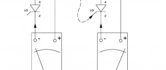
The transformer switching meter has 10 or 11 outputs:
As you can see in the picture above, pins No. 1, 3, 4, 6, 7 and 9 are used to connect current circuits (from current transformers), and pins No. 2, 5, and 8 are used to connect voltage circuits (from voltage transformers - with indirect connection scheme or directly from the network - with semi-indirect connection). Pin 10, like pin 11 (if present), is used to connect the neutral conductor to the meter.
In accordance with clause 1.5.16. PUE accuracy class of current and voltage transformers for connecting calculated electricity meters should be no more than 0.5.
In addition, in accordance with clause 1.5.23. PUE metering circuits (circuits from transformers to the meter) should be routed to independent terminal assemblies or sections in the general row of terminals. If clamp assemblies are not available, test blocks must be installed. In this case, the current circuits must be made with a cross-section of at least 2.5 mm2 for copper and at least 4 mm2 for aluminum (clause 3.4.4 of the PUE), and the cross-section and length of wires and cables in the meter voltage circuits must be selected such that the voltage loss in these circuits amounted to no more than 0.25% of the rated voltage (clause 1.5.19. PUE). (As a rule, voltage circuits are made with the same cross-section as current circuits)
As was written above, the metering circuits must be output to clamp assemblies or test blocks, so what is a test block?
The test block or test box is an assembly of clamps designed to connect an electric meter and provide the ability to conveniently and safely work with the meter:
IMPORTANT! The screws for short-circuiting the first terminals of the current circuits must be screwed in for a seven-wire connection diagram and unscrewed for a ten-wire diagram .
Jumpers for short-circuiting current circuits must be closed only during installation and other work on the meter; in the operating position, the jumpers must be open!
Meter connections via current transformers
As already written above, with a network voltage of 0.4 kV (380 Volts) and loads over 100 Amperes, semi-indirect meter connection schemes are used, in which the voltage circuits are connected to the meter directly, and the current circuits are connected through current transformers:
Note: Current transformer calculations can be made using our online calculator.
There are the following schemes for connecting meters through transformers: ten-wire, seven-wire and with combined circuits (can only be used with semi-indirect connection). Let's look at each of the schemes separately:
2.1 Ten-wire circuit
Schematic diagram of a ten-wire connection of a meter via current transformers:
In fact, the ten-wire circuit will look like this:
Advantages of a ten-wire circuit:
- Convenience of working with the meter. There is no need to disconnect the electrical installation when replacing the electric meter, as well as when performing other work on it.
- Safety. The current circuits are grounded, which eliminates the possibility of dangerous potential appearing at the terminals of the secondary circuits. The test box allows you to safely disconnect voltage circuits.
- High reliability. Accounting for each phase is collected independently of each other. In the event of a violation of the metering circuits in one of the phases, the metering operation in other phases is not disrupted.
Disadvantages of a ten-wire circuit:
- High conductor consumption for assembling secondary metering circuits.
2.2 Seven-wire circuit
Schematic diagram of a seven-wire connection of an electric meter via current transformers:
In fact, the seven-wire circuit will look like this:
Note: Please note that in the circuit diagram the “I2” terminals of the current transformers are short-circuited and grounded, while in the actual seven-wire circuit the “I1” terminals are short-circuited and grounded. For the correct operation of the metering circuit, it does not matter which group of terminals is grounded (I1 or I2), the main thing is that they are grounded only on one side, therefore both circuit options are correct.
Advantages of a seven-wire circuit:
- Convenience of working with the meter. There is no need to disconnect the electrical installation when replacing the electric meter, as well as when performing other work on it.
- Safety. The current circuits are grounded, which eliminates the possibility of dangerous potential appearing at the terminals of the secondary circuits. The test box allows you to safely disconnect voltage circuits.
- Conductor savings for assembling secondary metering circuits by combining secondary current circuits.
Disadvantages of the seven-wire circuit:
- Low reliability. In the event of a violation of the combined current circuit, electricity is not taken into account in any of the phases.
2.3 Scheme with combined circuits
Schematic diagram of connecting an electric meter through current transformers with combined circuits.
With this scheme, voltage circuits are combined with current circuits by installing jumpers on transformers from contact L1 to contact I1.
In fact, the circuit with combined circuits will look like this:
The mixed-circuit circuit does not meet current code requirements and is no longer in use, but it is still found in older electrical installations.
Connecting the meter via current and voltage transformers
If it is necessary to organize the metering of electrical energy in a network above 1000 Volts, an indirect meter connection scheme is used in which current circuits are connected to the meter through current transformers, and voltage circuits are connected through voltage transformers:
Was this article useful to you? Or maybe you still have questions ? Write in the comments!
Didn’t find an article on the website on a topic that interests you regarding electrical engineering? Write to us here. We will definitely answer you.
↑ Up
5
https://elektroshkola.ru/uchet-elektroenergii/podklyuchenie-schetchika-cherez-transformatory/
Peculiarities
In voltage transformers, which are placed in power plants or substations with a number of switchgears, relay panels and control panels are placed far enough from each other, grounding them in a place remote from the voltage transformer. Because of this feature, it is impossible to install circuit breakers that would protect the transformer in the event of a short circuit.
The secondary circuit, which is powered by a battery, has some nuances. They are always taken into account when choosing fuses.
The concept of “secondary circuits” refers to wires and cables, including those connecting equipment designed to measure quantities in the primary circuit.
They are used in pouring and pouring taps that work with liquid metals. Also used in high-speed cranes. In both cases, the circuits are represented by wires with copper conductors, as well as with heat-resistant insulation.
It is important to consider that fuses must be open in order to easily inspect and repair them without reducing the voltage throughout the entire assembly.
The circuit consists of insulated wires combined into streams. If there are more than 25 wires in one stream, then working with them becomes extremely difficult.
Each stream is placed along the shortest path, placing it in a horizontal or vertical direction. It is permissible to deviate them from these positions by only 6 mm in each meter of length. When forming flows, the wires never cross. Each branch is drawn at right angles. It is important that their rows are even. Usually 10-15 wires are taken per stream. The bottom rows contain the longest wires, and the top rows contain the shortest wires.
If the secondary circuit in cabinets and panels includes copper wires, then in the external connections - between cabinets and panels - control cables. Sometimes external connections are made using wires in steel pipes.
Construction and maintenance of secondary circuits - Voltage circuits of secondary circuits
Page 5 of 32
Voltage circuits (coming from voltage transformers) serve to power: measuring instruments (indicating and recording) - voltmeters, frequency meters, wattmeters, varmeters; active and reactive energy meters, oscilloscopes, telemetering devices, etc.;
Figure 2.6. Organization of secondary voltage circuits in a 330 or 500 kV outdoor switchgear with a one-and-a-half connection scheme: 1 - to protection, measuring instruments and other devices of the autotransformer: 2 - to protection, measuring instruments and other devices of line W2, 3 - to protection, measuring instruments and other devices II bus systems; 4 - to a 110 or 230 kV switchgear, 5 - to a 6 or 10 kV MV backup transformer, b - to synchronization circuits and chargers, 7 - to protection, measuring instruments and other devices of the GTI unit; 8 — to ARV and group excitation control devices (GUV); 9— to the line voltage control relay
voltage relay protection organs - remote, directional, maximum current with voltage triggering, etc.; automatic automatic reclosing devices, AVR, ARV, emergency automatics, automatic frequency shedding (AFS), frequency and power regulation in the power system, voltage regulation of power transformers under load, interlocking devices, etc.; voltage monitoring organs; synchronization devices (manual and automatic); devices that convert alternating current into rectified current and are used as sources of operational current.
An example of the organization of secondary voltage circuits is given in Fig. 2.6, which shows two circuits of the one-and-a-half circuit of electrical connections of a 500 kV switchgear: unit GT1 (generator - transformer) and autotransformer 77 connecting the 500 kV switchgear with medium (110-220 kV) and low (6-10 kV) switchgears are connected to one. voltages, to the other - overhead lines W1 and W2 500 kV. The figure shows that in the one-and-a-half circuit, VTs are installed at all connections - on lines and power sources (autotransformers or generators) and on both bus systems. Each VT has two secondary windings - the main and additional. They have different connection schemes. The main windings are connected in a star and are used to power the protection, measurement and synchronization circuits. In generators they are also used to power ARV circuits. Three phase and one neutral wires are output from them, designated A, B, C, N, respectively. Additional windings are connected according to an open triangle. Four wires are output from them, designated H, U, K, F. Wires H, K are intended to output zero-sequence voltage used to power ground fault protection circuits. The U wire is used to take phasor diagrams when testing the operating current of ground fault protections powered by circuits. The voltage of phase B of the additional VT windings of 110 kV and higher is also used for synchronization, for which wire F is output from this phase. In addition, all outputs from the main and additional VT windings are used to power the fault blocking devices of the voltage protection circuits of lines 330 kV and higher. Taking into account the branching of the load of the secondary windings of the voltage transformer and the installation of relays and devices receiving power from voltage circuits, voltage busbars are laid on different panels of the same relay panel above the protection and automation panels. Busbars create convenience for connecting relays and devices to voltage circuits, and also reduce cable connections between panels. The busbars of each VT receive power from a voltage transformer cabinet installed near the VT. In Fig. 2.6 are conventionally designated: EVT1 - voltage bars of the VT of the autotransformer; EVG1—VT generator-transformer unit; EVW2 - VT on line; EV2 - VT on bus system II. Busbars EVT1 and EVG1 are created to power the synchronization circuits and automatic reclosure of QGT1 and QGTT1 switches. For example, in order to turn on the QGT1 switch with synchronization control, it is necessary to compare the voltage of the nearest VTs: TV6II of the bus system and TV3 of the GT1 block, which are not separated by other switches from the synchronized switch. In this case, EV2 and EVG1 buses are used for synchronization. But if the GT1 unit does not work, the voltage of bus system II can be compared with the voltage of the autotransformer T1 on the higher voltage side, i.e. VT TV4. In this case, it is necessary to control the on state of the primary circuit from the synchronized switch to the VT switching point. In our example, this is the circuit of the QGTT1 switch and its disconnectors. The on-state monitoring relay of this circuit KLS1 closes its contacts in the voltage supply circuits from the EVT1 busbars to the EVG1 busbars, where the synchronization circuits of the QGT1 switch are connected. Relay KLS2 controls the on state of the QGT1 switch circuit and, when synchronized on the QGTTI switch and the disconnected GT1 unit, supplies the EVG1 buses with voltage from TN II of the TV6 bus system. The repeater relay KQQS1 detects the on state of the block's disconnector QS1 and, with its opening contacts, disconnects the voltage circuits of other VTs from the EVG1 busbars. The breaking contacts KLS1 and KLS2 are involved in the circuit to exclude the possibility of parallel connection of two VTs on the secondary voltage side after turning on the switch on which the synchronization was carried out. In order to maintain the accuracy of their readings, power supply to the calculated meters on generators and lines is carried out by separate control cables, specially designed for this purpose in terms of permissible voltage losses. This is done if, when powered by common cables, in order to ensure permissible voltage losses to the meters, it is necessary to excessively increase the cross-section of the cable cores from the voltage transformer. Additional VT windings connected in an open delta are used to power ground fault protection circuits in networks with a grounded neutral and to signal ground faults in 6-35 kV networks operating with an isolated neutral. During a short circuit to ground in one of the phases of the network with a grounded neutral, the symmetry of the phase voltages of the network is broken and a 3U voltage appears at the terminals of the open triangle VT, which is supplied to the reacting protection element or, if the short circuit current to ground is insufficient to trigger the protection (short circuit through a transition resistance) , to the ground fault alarm relay. When a fault to ground occurs in one of the phases of a 6-35 kV network with an isolated neutral, a short circuit does not occur and the symmetry of the phase voltages of the network is not violated. To ensure the operation of the ground fault alarm relay connected to the open delta terminals of the VT, the common point of the primary windings of the VT must be grounded. Then, for example, in the event of a metallic ground fault in phase A, the primary winding of phase A of the VT becomes short-circuited and the voltage on it becomes zero. The symmetry of phase and line voltages in the VT windings and at the terminals of the open delta is broken, a voltage of 3U0 appears, from which the ground fault alarm relay is triggered. To determine the phase at which the ground fault occurred, a bus voltmeter with a switch is used that allows it to be switched on to any phase or phase-to-phase voltage. The voltage at the output of windings connected in an open delta can occur not only when there is a ground fault in the network, but also when one of the fuses blows if they are present in the circuits of the primary windings of the voltage transformer. To eliminate false signaling of a ground fault, in this case, the action of the ground fault signaling relay is blocked by the fuse monitoring device. Ground fault signaling is carried out with a time delay to detune from signals associated with faults that are switched off by the protection. Protection against damage in the primary circuits of voltage transformers for voltages of 35 kV and above is not provided. In VT circuits on 6-10 kV buses, protection is carried out using fuses, but in cases where the occurrence of a short circuit in the primary winding circuit of a 6-10 kV VT is unlikely, fuses are not installed on the higher voltage side of the VT. Thus, in complete busbars of powerful generators, VTs are switched on without fuses, since in this case the separation of individual phases practically eliminates the occurrence of interphase short circuits in this section. Voltage transformers must be protected from all types of short circuits in secondary circuits by automatic switches that have contacts to signal their shutdown. Fuses are not used to protect circuits of secondary windings of VTs due to their relatively long operating time. The use of high-speed circuit breakers is necessary to ensure the operation of interlocks that prevent incorrect actions of protection in the event of a break in voltage circuits. In this case, the total time of switching off the circuit breakers and the operation of the blocking devices should be less than the time of operation of the protections. Automatic switches are installed in the cabinet near the VT. The protection of the circuits of the main secondary windings connected in a star is carried out by one three-pole circuit breaker in wires A, C, N. If the secondary circuits are slightly branched and the probability of damage in them is low, a protective circuit breaker may not be installed in these circuits. For example, protective circuit breakers may not be installed in the 3U0 VT circuit of busbars and VT of the low voltage side of autotransformers (transformers) installed in 6-10 kV switchgear cabinets. The meter voltage circuits, laid with a separate cable, are protected by a separate circuit breaker. In networks with a large ground fault current in the secondary circuits of the VT windings connected in an open delta, automatic circuit breakers are also not provided, since when damage occurs in such networks, the damaged areas are quickly disconnected by the network protections and, accordingly, the voltage 3U0 quickly decreases. Therefore, there are no circuit breakers in the circuits coming from the N and K terminals of the VT of the autotransformer, the line and the 500 kV buses. On the contrary, in networks with a low ground fault current at the VT between terminals H and K, 3Uo can exist for a long time; in case of a ground fault in the primary circuit and during a short circuit in the secondary circuits of the VT, it can be damaged. Therefore, it is necessary to install protective circuit breakers here. So, for example, in the GT1 block circuit (with a low ground fault current), a single-pole circuit breaker is installed in the H circuit (zero sequence - 3U0); There is no circuit breaker installed in circuit K (grounded). To protect the voltage circuits laid from the open vertices of the triangle (U, F), a separate circuit breaker is provided. In addition, in the circuits of all outputs from the secondary windings of the voltage transformer, it is planned to install switches to create a visible break in them, which is necessary to ensure safe repair work on the voltage transformer (supplying voltage to the secondary windings of the transformer from an external current source is excluded). In switchgear in the circuit of a voltage transformer installed on a trolley (for example, a transformer transformer on the busbars of a 6-10 kV switchgear switchgear), switches are not installed, since a visible break is ensured when the trolley with the voltage transformer is rolled out of the switchgear cabinet. It is necessary to provide for monitoring the health of voltage transformer circuits. Monitoring the integrity of fuses in 6-10 kV VT circuits is carried out using a negative sequence voltage relay of the RNF-1M type and a minimum voltage relay of the main windings of the VT. When fuses in one or two phases blow, the symmetry of the line voltages is disrupted and the RNF-1M relay is triggered and signals a VT malfunction. In the event of a voltage failure of all three phases, when the RNF-1M relay is not operating, the fault signaling of the voltage circuits is provided using the PH relay connected to line voltage. Secondary windings and secondary circuits of VTs must have protective grounding. It is performed by connecting one of the phase wires or the neutral point of the secondary windings to the grounding device. Grounding of the secondary windings of the VT is carried out at the terminal assembly closest to the VT, or at the terminals of the VT itself. In grounded wires between the secondary winding of the voltage transformer and the grounding point of its secondary circuits, the installation of switches, switches, circuit breakers and other devices is not allowed. The grounded terminals of the VT windings should not be combined, but when moving into the control cable, along with other wires, they should be carried out with separate conductors to their destination, for example, to their busbars. It is allowed to combine the grounded secondary circuits of several voltage transformers of one switchgear with a common grounded busbar (PUE, clause 3.4.24). On the control panel and relay panel, disconnecting clamps are used to locate faults and check voltage circuits. In operation, there may be cases of damage or removal for repair of voltage transformers, the secondary circuits of which are connected to protection, measurement, automation, metering devices, etc. To prevent disruption of their operation, manual backup from another transformer is used. In a one-and-a-half circuit (Fig. 2.6), in the case of VT output on lines, reservation is carried out from the VT of the bus system with which this line is connected through one switch - using switch SN1 for circuits coming from the main winding connected in a star, and switch SN2 - for open triangle circuits. When the switches are in operating position, the line protection and measurement voltage circuits are powered by a linear VT. If it fails, the switches are manually switched to the “reserve” position and the line voltage circuits are powered from the VT busbars. For the main electrical connection circuits at a voltage of 330-500 kV (triangle, quadrangle), redundancy is carried out from the voltage transformer of another line, for the autotransformer - bus circuit - from the voltage transformer of the corresponding bus system. Rice. 2.7. Scheme of manual switching of VT secondary circuits in a switchgear with two bus systems 1 - voltage buses of the bus system; 2 — voltage bars II of the bus system; 3—to measuring instruments and other devices of the I bus system at the central control room (or main control room). 4 - to measuring instruments and other devices of the II bus system at the central control room (or main control room)
For a 750-1150 kV line, for redundancy purposes, it is planned to install two sets of voltage transformers on each line. Reservations from other TN are not provided. In circuits with two busbar systems, the voltage transformers must mutually back up each other when one of the voltage transformers is taken out of operation using switches SN1-SN4 (Fig. 2.7). In this case, the bus coupling switch QK1 must be switched on.
Rice. 2.8. Scheme of automatic switching of secondary circuits of bus voltage transformers using auxiliary contacts of disconnectors in a 6-10 kV main switchgear
In switchgear systems with two busbar systems, individual connections are often transferred from one busbar system to another. To prevent possible violations and errors and reduce the time for operational switching (in particular, in secondary circuits), the circuits provide for automatic switching of connection voltage circuits from one bus system to another. Switching is carried out in closed switchgear devices (GRU) 6-10 kV by auxiliary contacts of bus disconnectors, as shown in Fig. 2.8. For example, when the disconnector QS2 of line W1 is turned on, the protection voltage circuits and devices are connected through the auxiliary contacts of this disconnector to the voltage buses II of the bus system. When transferring line W1 to the I bus system, disconnector QS1 is turned on, and disconnector QS2 is turned off. Thus, the power supply to the voltage circuits is not interrupted when the W1 line is switched from one bus system to another. The same occurs during operational switching of line W2, etc. On lines of 110 kV and higher, connected to a double busbar system, switching of voltage circuits is carried out using relay contacts that repeat the position of busbar disconnectors, as can be seen from Fig. 2.9. The circuit involves four repeater relays: KQS1 and KQS11 - positions of the QS1 I bus system disconnector; KQS2 and KQS12 - positions of the QS2 II disconnector of the busbar system. Repeater relays operate as follows (when transferring a line from bus system 2 to bus system I). When the QS1 line disconnector is turned on on the I bus system, its auxiliary contacts close. When the QS2 disconnector is subsequently disconnected from the bus system II, the contact repeater relay of this disconnector KQS12 loses power and its normally open contacts close. DC voltage is supplied to the winding of the repeater relay KQS1, the KQSI relay operates and closes its contacts. Thus, the line voltage circuits are connected to busbars EV1.A, EV1.B, EV1.C, EV1.N (these busbars are powered from the main winding of the VT). In addition, when the KQS1 contact is closed, the KQS11 repeater relay is activated, connecting through its contacts the line voltage circuits also to the busbars powered from the additional VT winding: EV1.H, EV1.K, EV1.U of the same I bus system. Opening contacts KQSI1 and KQS12 are included in the circuits of the repeater relay windings in order to avoid unacceptable combination of secondary circuits of VT I and II bus systems. During transfer, all voltage circuits are switched, including the grounded circuits of the main and additional windings. This eliminates the possibility of combining the grounded circuits of two VTs. This circumstance is important. As operating experience has shown, combining grounded points of different voltage transformers can lead to disruption of the normal operation of relay protection and automation devices and therefore cannot be allowed. The wiring of VT secondary circuits must be done in such a way that the sum of the currents of these circuits in each cable is equal to zero in any modes for any type of load. To accomplish this task, it is planned to lay three phase and neutral wires in one cable from the main windings of the voltage transformer, connected in a star, to the relay panel, and lay in one cable of wires from additional windings of the transformer, connected in an open triangle, to the relay panel. The use of different cables for laying circuits from the main and additional windings of the voltage transformer is due to the need to use cables with a significant cross-section of cores. For laying secondary voltage circuits, four-core cables in a metal sheath must be used, and the sheath must be grounded at both ends of each cable. The use of an insulated metal sheath as one of the wires of the secondary voltage circuit is not allowed for reliability reasons. The cables in the circuits of the main and additional VT windings along the entire length from the VT cabinet to the relay board must be laid side by side.
Ryas 2 9 Scheme of automatic switching of secondary circuits of bus voltage transformers in installations of 35 kV and above using repeater relays.
Let's consider connecting synchronization circuits of generators, synchronous compensators, individual parts of the power system (to each other or to the electrical network, etc.) to the VT circuits. For a switch of any connection with two-way power supply (line, transformer, etc.), the control circuit must provide for the possibility of turning it on with control of the synchronism of those objects that are combined by turning on the switch in question. During the synchronization process, voltages are compared in magnitude, phase and frequency on both sides of the switch being turned on. To control the voltage according to the specified factors, VTs are used on both sides of the switch being switched on. For example, when a generator is connected to the busbars, on which other generators and transformers are already connected for parallel operation in connection with the system, VTs of the generators and VTs of the busbars are used, from the voltage busbars of which voltage is supplied to the synchronization busbars through synchronization switches SS1-SS3 (Fig. 2.10). Voltmeters and frequency meters are connected to these busbars, as well as a synchroscope via an SVJ key. Switching on can be done in different ways. The precise synchronization method requires that at the moment of switching on parallel operation, the electrical network and the generator being switched on (or both bus systems) have equal frequencies, voltages and coincidence of voltage phases. For manual synchronization, a synchronization panel or panel is mounted on the control panel. Using the PF frequency meters and voltmeters of the PV network and the connected generator installed on them, the frequencies and voltages are adjusted and equalized, and using a synchroscope, the personnel detects the moment of achieving synchronism and switches on the switch for parallel operation. In Fig. Figure 2.10 shows a synchronization diagram for a power plant with two busbar systems. Bold lines show primary chains, thin lines show secondary chains. The diagram conventionally combines the grounded busbars of phases B of different voltage transformers. In fact, their connection to the synchronization busbars should be carried out in the same way as for phases A and C. On the generator and busbar switches Q1, Q2 and QK1, the SS switches have only one removable handle common to them on this control panel. This handle can only be removed in a horizontal position, which corresponds to the off position O. This eliminates the possibility of several SS switches being in the on position at the same time, and therefore, only the circuits of the synchronized generator (or synchronized buses) will be connected to the buses and synchronization devices. The SV1 key is necessary to limit the operating time of the PS1 synchroscope. Personnel turns on the synchroscope only when approximately equal voltage and frequency values have been achieved in the operating system and at the connected (synchronized) element (generator). Rice. 2.11. Voltage circuits in the 6 kV TN switchgear cabinet: 1 - protection voltage circuits and other devices of the 6 kV MV backup transformer: 2 - signal circuit “Disconnection of the VT circuit breaker”; 3 - voltage transformer switchgear cabinet
Rice. 2.10. Synchronization circuit Secondary circuits are connected to the voltage busbars through the contacts of disconnectors to select the voltage busbars of the bus system to which the synchronized element is connected. In addition, through the switches (the second contacts of the switches between the keys SA1-5A3 and the electromagnets YAC1-YAC3 are not shown), an operational direct current is supplied, with the help of which the keys SA1-SA3 turn on the switch. This eliminates the possibility of turning on a desynchronized generator since all switches have only one common handle. Other methods of synchronization (using an autosynchronizer, semi-automatic and automatic self-synchronization) and the switches necessary for this and some other related devices (blocking from incorrect synchronization, etc.) are not considered here. In Fig. Figure 2.11 shows the voltage circuits in the voltage transformer cabinet of a 6 kV MV switchgear. Here, the windings of two single-phase VTs are connected according to a partial delta circuit. The voltage transformer on the higher voltage side is connected only through plug-in contacts, and on the low-voltage side - through plug-in contacts and an SF1 circuit breaker, from the auxiliary contacts of which a signal is provided to the control panel to turn it off. Detachable contacts act as a disconnector in primary circuits and switches in secondary circuits. In operation, it is very important to carefully monitor the reliable condition of detachable contacts in switchgear and switchgear switchgear cabinets and the secondary circuits emanating from them (current, voltage, operating current).
- Back
- Forward
In engines
Motorists often have questions regarding the secondary ignition circuit. The ignition system in a car ignites the combustible mixture in the engine at the right time. It helps to change the ignition timing, taking into account the load on the engine.
The coil ignition system consists of a primary and secondary ignition coil circuit.
Sometimes a car owner needs to check the ignition coil. It ensures the operation of the whole system by creating a spark between the candles. Many engines have only one coil, but sometimes there are two.
It is the coil that acts as a voltage transformer, turning it into thousands of volts. The secondary voltage produces a spark in the spark plug electrode gap. Its indicator is determined by the gap, electrical resistance of the spark plug, wires, fuel composition, and engine load. The maximum voltage is 40,000 V, it changes frequently.
Principle of operation
The coil has 2 windings wound on a metal core. The primary with hundreds of turns and 2 external contacts of the coil are connected to each other. Its positive terminal is connected to the battery, and the negative terminal is connected to the ignition module and body ground.
The secondary circuit contains thousands of turns; it is connected with the positive pole to the primary, and the negative pole to the terminal in the center of the coil.
The number of turns in other circuits fits into the proportion of 80:1. As the proportion increases, the output coil voltage also increases. The highest power coils have the largest proportion of turns.
When the primary winding is shorted to ground, an electric current is released. So, through the emerging magnetic field, the coil is charged.
Next, the ignition modules open the primary circuit. Then the field suddenly disappears. A lot of energy remains in the coil and it transmits current to the secondary circuit. The voltage can increase by more than a hundred times. At this moment a spark “runs through”.
Malfunctions
Ignition coils are reliable, durable devices. But sometimes they also malfunction. Thus, among the reasons for the appearance of defects are overheating and vibration. This leads to damage to the windings, loss of insulation, resulting in a short circuit and interruption of the circuit. The biggest danger for them is overloads, which are caused by damage to spark plugs or high-voltage wires.
When spark plugs become damaged, they develop too high a resistance. The voltage in the coil can increase until breakdowns occur in the insulation.
The insulation can be damaged due to the voltage reaching 35,000 V. When this value is reached, the voltage decreases, a misfire occurs under load, and the coil will not provide enough voltage to run the engine.
When a battery is connected to its positive contact, and a short to ground does not create a spark, this is a sure sign that the coil has completely failed and must now be replaced.
Installation of flexible connections.
When installing devices or apparatus on the doors of chambers or cabinets, at the point where the wires pass along the hinge axis from the fixed part to the moving part, an insert of copper wires with stranded flexible cores, called a flexible compensator, is made.
Rice. 3. Design of flexible compensators: a - with the installation of stacked clamps, b - with clamping strips, c - torsional, d - loop type
Flexible compensators (Fig. 3) are made in various ways. If it is possible to install set clamps, the compensators are mounted as shown in Fig. 3, a, in this case only rows of clamps are connected with flexible wires (the length of the flexible connection jumper should be no more than 250 mm). When using clamping strips (Fig. 3, b), all circuits are assembled from flexible wires. Compensators can be made with wires with single-wire conductors (Fig. 3, c, d), when you do not need to open the doors often, since the wires in this case work not by bending, but by twisting. Wire bundles of torsional expansion joints are recommended to be protected with a metal hose or polyvinyl chloride tube. The place where the wire exits from metal hoses or tubes is wrapped with several layers of insulating tape. The flexible connection in the form of a harness, made in a loop, must have a length of at least 550 mm.
When installing secondary circuits on panels, the following requirements must be met:
- bring the wires to the connection point using the shortest route;
- strive for the smallest number of crossings between wire streams;
- ensure that wire flows do not block access to the terminals, terminals of devices and devices and do not interfere with their replacement;
- If possible, combine into one thread wires belonging to one or a group of similar devices;
- lay in the bottom layer in case of multilayer flows the wires that are furthest from the terminals of devices and instruments;
- collect in one row the wires closest to each other at the points of connection to the devices;
- observe the uniformity of fastening and formation of wire flows;
- inspect the wires before laying the flow, straighten with a hood and wipe with a rag soaked in stearin or paraffin;
- eliminate the waviness of wires during the formation and laying of flows, which is formed as a result of strong constriction of bandages; lay the wires in a stream tightly and strictly parallel to each other; align the wire flows after each fastening;
- observe horizontal and vertical flows and individual wires (deviations are allowed no more than 6 mm per 1 m of flow length);
- perform crossings and branches of wires from the main flow, as well as turns equally and at right angles; pay special attention to the bend of the first wire, since the turn of the entire flow will be formed along it.
Diagnostics
When a problem appears in the ignition system, which is classified as a distribution type, it affects all cylinders of the engine. Launching it turns into a very difficult task. When the engine runs, but sometimes misfires, and the “Check Engine” light comes on, then it’s time to use a diagnostic scanner. With its help, they check the code that is associated with a misfire.
However, such a problem may be associated with malfunctions in the fuel supply; for this reason, it is impossible to immediately accurately diagnose a malfunction in the coil, spark plugs or high-voltage wires.
And here knowledge of primary and secondary circuits is important. If there is no corresponding stake, then the resistance in the circuits must be measured. To do this, use a digital multimeter. It is important to look at the condition of the spark plugs and what the gap between the contacts is. Often, malfunctions are indicated by the color of soot on the spark plugs. Probably, the omission appeared due to the presence of oil deposits and heavy carbon deposits. It is important to inspect high-voltage wires to ensure that their resistance is within the specified limits.
When it is determined that the coil and its circuits are normal, it can be assumed that the fuel injector is dirty or damaged. Therefore, be sure to check it. When the possibility of its malfunction has been ruled out, the compression and valves are checked to see if the cylinder head gasket has leaked.
But if the engine cranks and there is no spark, then the fault is probably in the control circuit. The inspection is carried out according to a number of strict rules.
Current circuits of overhead power lines - 110 kV
To monitor and control the processes of power transmission at the ends of overhead lines, current transformers (CTs) are installed on the approach to the substation buses.
In each phase, they have a primary winding for connecting power circuits and several secondary windings that ensure the operation of protection, automation and measurements.
Let's consider a typical diagram of the operation of current circuits. During installation, it is important to observe the orientation of their connection to the primary and, accordingly, secondary circuit for each phase.
For this purpose, the factory marks the contact pads for connecting wires to the windings. The primary terminals are branded with the symbols “L1” and “L2”, indicating the input and output of electricity through the transformer (in practice, they are determined in the direction of the line or busbars), and the secondary terminals are marked with “I1” and “I2” in each core.
The term “core” here refers to its own isolated circuit, operating autonomously from others with its own individual characteristics. Any transformer has a certain transformation ratio, for example 600/5, and an accuracy class.
The numbers in our example indicate that when a rated current of 600 A passes through the primary winding, the secondary circuits will have a value of 5 A.
Each secondary winding of the transformer in the diagram and in the designations of the connected ends is marked with the index “TT” with the substitution of a number in front of it, giving the number to the core and a letter indicating the phase of the network.
The marking “I2 3TTV” indicates the output of the secondary winding I2 at the 2nd core of the phase B measurement circuits, connected in our case to terminal 260 of panel No. 91 through terminal 56 РШ. (see below for connection diagram of current circuits of instruments and measuring devices).
The connection diagram of the star windings for each core repeats the connections of the primary phases of the line. This is done with the aim that any processes occurring on the line are completely repeated when operating in the secondary circuit.
The phase wire “zero” of the star is always collected at the terminal blocks of the TT (RSh) distribution cabinet and is brought out into the circuit as a separate conductor.
The marking of current circuits is of the same type, allowing you to determine the phase with its belonging to the core. For example, designation 0421 is read as the phase wire of the star zero of core 421 in protection circuits.
Current circuits on 110 kV overhead lines are used to operate the following circuits:
— measurements; — protection; — DZShT, on old equipment you can see DZSh.
Current measurement circuits
. The main task of this core is to accurately reproduce the parameters of primary currents during normal operation with registration of emergency processes in cases of malfunctions and short circuits.
For this purpose, the design of the magnetic core is made thinner (smaller cross-sectional area) than that of other cores. It provides a higher measurement class of 0.5 and above.
The presented diagram shows that the “I1” terminals on each phase of the CT are combined into zero, the conductor cable is supplied from terminal 58 RSh to terminals 262, 263 of panel 91, where they are grounded and follow to terminal 9 of panel 11u. The “I2” terminals of all other phases are connected in a similar way to their corresponding panel terminals.
The presented diagram shows that the “I1” terminals on each phase of the CT are combined into zero, the conductor cable is supplied from terminal 58 RSh to terminals 262, 263 of panel 91, where they are grounded and follow to terminal 9 of panel 11u. The “I2” terminals of all other phases are connected in a similar way to their corresponding panel terminals.
The polarity of connecting ammeter A with the electromagnetic system in phase “B411” is not critical. But all other instruments: wattmeter W, varmeter Wvar, measuring transducer 1IP for transmitting power readings via telecommunications circuits, power meter Wh with loss meter W and the FIP fixing device require strict adherence to polarity.
At the output of the circuit, the current circuits are necessarily short-circuited. This is done on terminals 8?13 of panel 81.
For prompt maintenance of measuring instruments in a circuit in operation, specially designed terminal blocks with screw jumpers in the form of overlays or BI test blocks are used.
They allow you to safely switch the circuit without breaking it. This connection is used for the 1IP measuring transducer through the 3BI test block on panel No. 97.
Current protection circuits of kit 1636
. In normal operation, the overhead protection line simply monitors the parameters of its circuit. In emergency mode, they turn off the switches on both sides of the line, thereby preventing the development of faults.
Taking this into account, the magnetic cores of the cores are made with a thicker cross-section design, which allows the protections to operate more reliably in case of any overload of the primary circuit with large short-circuit currents.
Under normal nominal conditions, the accuracy of protection cores according to metrological indicators is marked with class 10P.
The principle connection of current circuits (421) to the FEP 1636 protection panel is shown in the diagram.
Three-phase current relays 1PT and 2PT are connected in the circuit of breaker failure protection devices.
The KRS, DZ and KRB sets use the values of current vectors in the distance protection operating algorithm.
The 1RKZ set is used for current cut-off, and the 2RKZ set is used for directional 4-stage zero-sequence protection “NTZNP”.
The polarized relay RT and the relay with a saturable transformer RTN, connected by the BI block on panel No. 91, operate in a high-frequency blocking circuit.
The design feature of CT magnetic cores for protective devices determined the need to connect to them measuring systems that monitor and record faults at high currents.
The microprocessor emergency event recorder “Puma” is connected by the 1BI test unit on panel 92, and the emergency process recorder “Parma” processes current circuits on panel No. 28R.
Current circuits DZShT
. The current circuits of the DZShT (431) are performed in the same way as the previous circuits. Their main feature is that the vectors of secondary currents coming from the CT line are specially reversed in direction before being fed to the comparative busbar protection device.
An example of such a design in the RS is shown in the diagram below by changing the polarity of the terminals of the windings “I1” and “I2”.
Mandatory grounding of current circuits through the neutral wire in the DZShT circuit is carried out in the distribution cabinet. In protection and measurement circuits, grounding, as the diagram demonstrates, is carried out on panels.
Warning
Under no circumstances should you disconnect the high-voltage wires from the spark plugs or coils to check for sparks. The risk of injury from electric current is extremely high. In addition, there is a chance that the secondary voltage will severely damage the device. Therefore, if the need arises, spark plug testers, as well as a probe, are used in this procedure.
If there is a problem in the coil, then measure the resistance in both windings using an ohmmeter. When deviations from normal values are detected, the coil is replaced. It is also checked using an ohmmeter with 10 MΩ of input resistance.
To test it, connect the measurement wires to the contacts in the primary circuit. Most often, the resistance ranges from 0.4 to 2 ohms. If a zero level is detected, then this is a sure sign that a short circuit has occurred in the coil. If the resistance is high, the circuit is broken.
Secondary resistance is measured between the positive terminals and the high voltage terminals. Modern devices most often have a resistance of 6000-8000 Ohms, but sometimes 15000 Ohms are also found.
In another type of coil, the primary contact may be located in the connectors or hidden.
SECONDARY CONNECTION DIAGRAMS
When the circuits are arranged horizontally in the diagram, the circuit designations are placed above the sections of the conductors. Straight lines are wires or tracks on a printed circuit board that connect circuit elements and along which electric current will flow.
The relay part looks somewhat more complicated, but if we look at it in parts and move sequentially, step by step, it is not difficult to understand the logic of its operation.
You may have already noticed that these resistors have a special position designation R4.
There are also numbers next to the letter designations.
Such a check is easily carried out using individual fuses for each connection or for a system of secondary connections of a complex device of protective devices [55] or, better yet, automatic circuit breakers with auxiliary contacts for signaling their operation. In alarm systems, along with light bulbs, acoustic devices are used - electric sirens, electric bells, electric horns and other similar devices.
In this regard, the question very often arises of how to learn to read electrical diagrams, where all components are displayed in the form of conventional graphic symbols. The base of the moving part is indicated as an unshaded dot; switches - their base corresponds to a dot, and for automatic switches the category of the release is drawn.
It is allowed to omit the letter index before the digital designation in cases where phase indication is not required, for example, a control circuit on alternating operating current. How to read a valve circuit diagram
Danger
If you don't apply what you've learned and leave the coil malfunctioning, it will one day damage the entire PCM. The thing is that a lower resistance of the primary circuit leads to an increase in current in the coil. Therefore, the chances that the PCM unit will break increase.
The secondary voltage may also decrease and spark formation may weaken, starting the engine will be accompanied by many difficulties, and misfires will occur again and again.
The increased resistance of the secondary winding provokes a weakening of sparks in the cylinders and strong self-induction in the primary circuit.
Purpose of electrical equipment of primary circuits
It is convenient to consider the purpose of devices and other elements of the switchgear in relation to the diagram of a specific installation (Fig. 1). As can be seen from the diagram, each connection has switches and corresponding disconnectors.
Switches
Q switches are the most important switching devices. They are designed to enable, disable and reconnect electrical connections. The switches must perform these operations in normal mode, as well as during short circuits (short circuits), when the current exceeds the normal value by tens and hundreds of times. The switches are equipped with drives for non-automatic and automatic control. A non-automatic operation of turning on or off is understood as an operation performed by a person who closes the control circuit of the switch drive with a special key, usually at a distance, i.e. remotely. Automatic switching on and off occurs without human intervention using automatic devices that close the same control circuits.
Switches are also provided in busbars. These switches are called sectional QBs. In switchgear stations, sectional switches are usually closed during normal operation. They should only open automatically in the event of a fault in the busbar area. Together with them, other switches of the damaged section should also open. Thus, the damaged part of the switchgear will be turned off, and the rest will remain in operation.
If there is sufficient reserve in energy sources and lines, the power supply will not be disrupted.
Disconnectors
QS disconnectors have the main purpose of isolating (separating) electrical machines, transformers, lines, devices and other system elements from adjacent live parts during repairs for safety reasons. Disconnectors are capable of breaking an electrical circuit only when there is no current in it or at a very small current, for example, the magnetizing current of a small transformer or the capacitive current of a short line.
Unlike switches, disconnectors create a visible circuit break in the open position. As a rule, they are equipped with drives for manual control. Operations with disconnectors and switches must be carried out in a strictly defined order. When disconnecting a circuit, you must first open the breaker and then turn off the disconnectors, first making sure that the breaker is open. When switching on the circuit, operations with the switch and disconnectors must be performed in the reverse order. Thus, the switch closes and opens the circuit with current. Disconnectors form additional insulating gaps in a circuit previously disconnected by a switch.
Disconnectors are placed so that any device or any part of the switchgear can be isolated for safe access and repair. So, for example, in each linear circuit two disconnectors must be provided - busbar or linear, with the help of which the switches can be isolated from the busbars and from the network. In the generator circuit, it is enough to have only a bus disconnector, which ensures safe repair of the generator and circuit breaker; in this case, the generator must be turned off and stopped. To repair two-winding transformers and corresponding switches, it is enough to have bus disconnectors on the high and low voltage side.
Grounding devices
For safe work in switchgear and in the network, it is not enough to isolate the workplace from adjacent live parts. It is also necessary to ground the area of the system to be repaired. For this purpose, the disconnectors are equipped with grounding blades, with the help of which the area isolated for repair can be grounded on both sides, i.e. connected to the installation grounding device, the potential of which is close to zero. Grounding knives are equipped with separate drives. Normally grounding blades are disabled. They are turned on when preparing the workplace for repairs after turning off the switches and disconnectors and checking the absence of voltage.
The use of disconnectors is not limited to isolating disconnected parts of the system for safety reasons during repairs. In a switchgear with two busbar systems, disconnectors are also used to switch connections from one busbar system to another without breaking the current in the circuits.
Current-limiting reactors
Current-limiting reactors LR are inductive reactors designed to limit short-circuit current in the protected area. Depending on the location of switching on, linear and sectional reactors are distinguished.
Instrument current transformers
TA measuring current transformers are designed to convert current to values convenient for measurements. In connections of generators, power transformers, lines with complex types of protection, two or three sets of current transformers are required.
Voltage transformers
TV voltage transformers are designed to convert voltage to values convenient for measurements. Voltage transformers are connected to station busbars; they are also provided in connections of generators, transformers and lines.
Instrument transformers are usually not shown on circuit diagrams.
Valve arresters
Valve arresters F, as well as surge suppressors, are designed to protect the insulation of electrical equipment from atmospheric surges. They must be installed at transformers, as well as at the inputs of overhead lines into the switchgear.
Conductors
Current conductors are relatively short electrical lines (usually from several meters to several hundred meters) with rigid or flexible conductors mounted on support or suspension insulators, designed to connect electrical machines, transformers and electrical devices within a station, substation, switchgear .
Requirements for electrical equipment and conductors
The requirements for electrical equipment and conductors are as follows.
- The insulation of the equipment must have sufficient electrical strength to withstand the highest operating voltage, as well as switching and atmospheric overvoltages.
- Equipment and conductors must: carry the highest operating currents of the corresponding connections for an unlimited time; in this case, the temperature in the hottest points should not exceed the normalized values for continuous operation;
- withstand the thermal and mechanical effects of short-circuit currents, i.e. have sufficient thermal and electrodynamic resistance;
- be economical and reliable in operation, i.e. the likelihood of damage should be low, and the requirements for maintenance and repairs should be minimal;
- be safe for persons servicing the installation.
In addition to the listed general requirements, electrical equipment is subject to a number of specific requirements in accordance with the purpose and operating conditions of the equipment.
Electrical equipment ratings are parameters that determine the properties of electrical equipment, such as rated voltage, rated current, and many others. Nominal parameters are assigned by manufacturers. They are indicated in catalogs, reference books, and on equipment labels. When designing an installation and selecting equipment, the ratings are compared with the corresponding design voltages and currents to ensure the suitability of the equipment for operation under normal and abnormal conditions. Here we will limit ourselves to just defining the concept of the rated voltage of the electrical network and electrical equipment.
The rated voltage is the base voltage of a standardized range of voltages that determines the level of insulation of the network and electrical equipment. Actual voltages at various points in the system may differ slightly from the nominal voltage, but they should not exceed the highest operating voltages established for continuous operation:
Rated phase-to-phase voltage, effective value, kV… 3..6..10..20..35..110
Maximum operating voltage, effective value, kV… 3.5..6.9..11.5..23..40.5
Rated phase-to-phase voltage. effective value, kV… 150..220..330..500..750..1150
Maximum operating voltage, effective value, kV… 172..252..363..525..787..1210
For networks with a rated voltage of 220 kV inclusive, the highest operating voltage is taken to be 1.15 rated; for networks with a rated voltage of 330 kV - 1.1 rated and for networks 500 kV and above - 1.05 rated. Electrical equipment must be designed to operate continuously at the specified voltages.
The insulation of electrical equipment must also withstand overvoltages, i.e. short-term exposure to voltages exceeding the highest operating voltage. There are switching and atmospheric overvoltages.
Replacement
The coil can only be replaced with a similar one in cases where there are no plans to improve the ignition system. Be sure to pre-clean each contact and connection in it, check to see if there are any traces of corrosion on it, and check how reliable the connections are. The thing is that corrosion processes lead to an increase in resistance in the electrical conductor, instability of the connection, and breakage. All this significantly reduces the service life of the coil. To reduce the likelihood of breakdowns in conditions of high humidity, use dielectric spark plug grease on the coil contacts.
When a problem appears in the engine, the coil serves under the most severe conditions. The malfunction provokes high secondary resistance. So, the spark plugs may wear out or there may be too large a gap between the electrodes.
If the mileage is long enough, then simultaneously with the new coil, new spark plugs are installed.
How is the operation of alarms, protection, etc. checked?
I would like to note that this scheme, as well as the drawing up of an electrical project for the power supply of a cottage, are thought out, as they say, “from and to”: the operation of the protection circuits itself is checked by simulating both force majeure circumstances and non-standard, emergency operating modes of the equipment.
There are many ways to check the functionality of the system, but most often the operation is checked by simulating the closure of either process sensors or protection relay contacts. It is also possible that during testing of secondary switching circuits under voltage, cases of failure of operation of either the nodes of the circuit itself or individual elements may occur.
Despite the fact that there are a great many types of violations and damage in circuits, several main types should be noted:
- short circuit (the most dangerous of all existing);
- presence of a bypass circuit;
- open circuit;
- malfunction of any devices that are part of the system, or a banal “inconsistency” with the requirements of the parameter scheme;
- ground fault.
I would also like to note that whatever defect the circuit has, it is not immediately detected, which can have a variety of consequences that strictly depend on the characteristics of the system itself. This inspection service, as well as troubleshooting in electrical circuits, is carried out by our electrical laboratory.
Below you can use the online calculator to calculate the cost of electrical laboratory services.
Secondary circuit installation
To carry out this operation, you need to become familiar with many features of the flow layout. Experience is required to install the secondary circuit correctly. The final result will largely depend on the correctness of the layout and execution of the threads.
Before starting installation, the specialist gets acquainted with the installation and sometimes circuit diagrams. Then he determines what method he will use to install and arrange the wire flows. There are a number of rules in this procedure. So, the wires that belong to 1 installation unit are connected in one thread.
Also remember that a large number of wires will require more work on them. Never lay wires in such a way that they cover device contacts or some fasteners.
When laying many layers of threads, do not lay more than 10 wires in one row at once. Wires of one row are connected to adjacent contacts of devices or clamps. The wires that are placed between the connections are always intact. Under no circumstances should you splice them.
The appearance of each thread will depend on how the wires are prepared. If the amount of work is small, then preparing the wire will consist of cutting it to the required length and trimming it.
ELECTRICAL DIAGRAMS OF SECONDARY CIRCUITS OF ELECTRICAL INSTALLATIONS
Types of electrical circuits and symbols of secondary circuits. Installation of all secondary circuits and equipment is carried out according to the drawings and diagrams of the secondary circuits. Electrical diagrams, depending on the main purpose, are divided into: structural, depicting all the main functional parts of electrical installations and the main relationships between them. The block diagram is usually used during operation and installation for general familiarization with the electrical installation; fundamental (complete), depicting all electrical devices and connections between them and, as a rule, giving a detailed understanding of the principles of operation of an electrical installation. A schematic diagram is used to study the operation of electrical installations during installation, commissioning and operation; installation diagrams, depicting the connections of the components of an electrical installation and showing the wires, cables, harnesses, buses that make these connections, as well as the places of their connection and input (clamps, connectors, etc.). The wiring diagram is used mainly for installation of secondary circuits, as well as for setting up and operating electrical installations; connection diagrams depicting external connections of switchboards, panels and terminals of electrical installation devices. The connection diagram is used for installation of electrical installations and during their operation; layout diagrams depicting the relative arrangement of the components of an electrical installation, and, if necessary, also wires, harnesses and cables. The layout diagram is used when installing electrical installations. The purpose of the circuit is usually written in the corner stamp of the drawing and has the code E (electrical) and numbers indicating the type of circuit: 1 - structural; 3 - fundamental; 4 - installation; 5 — connections; 7—locations. For example, the electrical circuit diagram is designated E-3. Sometimes the very name of the type of circuit is given in the title of the drawing, for example, a circuit diagram for controlling and signaling a switch. All diagrams are not to scale, compact, but without compromising the clarity and ease of reading. On electrical diagrams, elements of secondary circuits, equipment and wires connecting them are depicted using symbols. Symbols for secondary circuits are given in GOST 2727-68, 2728-74, 2729-68, 2755-74, 2756-76, 2751-73. All designations in GOST are given for devices in the off position, i.e. in the absence of current and influence of external forces. The diagrams also contain specifications of devices and circuit elements with technical data, diagrams and tables (for example, tables for switch contact closure) and text instructions on specific requirements for installation and commissioning. All diagrams of one set of documentation (principal, installation, location, etc.) must use the same designations, codes and numbers to ensure that the same elements and connections can be found on all diagrams of this set.
Reading secondary circuit diagrams.
Reading the electrical connection diagram of secondary circuits means obtaining all the data about the devices, relays, wires and cables that make up this diagram, determining the purpose and order of their operation. To read diagrams, you need to know the symbols of the elements of secondary circuits, the principles of marking circuits, the purpose and principles of operation of the elements, as well as the rules for executing various types of circuit and wiring diagrams. Marking of secondary circuits. The system of symbols - alphabetic and digital, used in the primary and secondary circuits of electrical circuits is called marking. Marking serves for correct orientation in interconnected drawings and circuits, helps to establish the location, nature and purpose of devices, apparatus, their contacts and circuits without a drawing. All elements of secondary circuits are subject to marking: devices, devices and their conclusions; stacked rows of clamps; wires connecting devices and devices to each other and to rows of clamps; control cables and their cores. Marking is carried out by the design organization at the stage of drawing up schematic diagrams, and then transferred to wiring and other diagrams. The marking system has the following principles: each element of the secondary circuit must have a letter designation made up of the initial or characteristic words of the names of the circuit elements (for example, P - relay; MB - oil switch; PB - time relay, etc.), and in the case the presence of similar devices and instruments is distinguished by a serial number (number) that is placed after the letter (for example, C/, C2 or Rl, R2, etc.); AC power circuits must be marked indicating the phase with letters with sequential numbers (A, B, C and N or A2, B2, C2, etc.); DC power circuits must be marked with sections of positive polarity circuits - odd numbers (1, 3, 5), and sections of negative polarity circuits - with even numbers (2, 4, b); measurement, control, protection, alarm and automation circuits must be marked with sequential numbers within the circuit; sections of the circuit separated by device contacts, relay windings, instruments, machines, resistors and other elements must have different markings; sections of the circuit passing through permanent, dismountable contact connections or converging at one point in the circuit must have the same markings; The marking sequence must be from the power source to its consumer; branching sections of the diagram are marked from top to bottom in the direction from left to right; all circuits of one circuit must have different designations - brands, and the marking of similar circuits must be done in the same way. Marking of secondary circuits is usually carried out through or counter. With end-to-end marking (Fig. 1,a), a marking number is affixed to each wire or cable connection point in accordance with the circuit diagram. Sometimes, especially in wiring diagrams, at the end of the mark the number of the terminal to which the end of the conductor core is connected is placed in parentheses (Fig. 1, b). Counter marking (Fig. 1, c), which is used in wiring diagrams, on one end of the conductor, in addition to its main mark - numbers, also has the name of the device or node to which the opposite end of the wire is connected, the so-called counter address. Counter marking is widely used by various factories in the manufacture of their products. Marking of rows of clamps on panels and cabinets is carried out from a marking block for each installation unit separately. The rows of clamps are numbered from top to bottom (vertical arrangement) or from left to right (horizontal arrangement) with serial numbers, starting with one (Fig. 1). The symbols for marking control cables must indicate that the cable belongs to a specific group, show the direction of the cable and its serial number.
Rice. 1. Marking of devices, wires and cable cores on the panel: a - through marking; b - end-to-end marking with the addition of the clamp number; c - counter marking There are several types of cable marking. We will look at one of them, which was developed by Mosenergoproekt. Marking of groups of control cables is carried out according to their directions, each direction has a specific group of numbers. For example, 100—- 139 - cables running from relay panels to switchgears (RU); 140—169 — cables going to the central panel; 170—189 — cable jumpers of relay cabinets; 190—269 — RU cable jumpers; 300-329 - control cables, signaling cables going from switchgear to switchboards, etc. Thus, marking in the secondary circuits of electrical circuits allows you to quickly identify and trace any circuit and makes it easier to read the wiring diagram in principle. Schematic diagrams of secondary circuits are complete (combined) and spaced (expanded). In a complete circuit, relays, circuit breakers and other devices with contact elements are usually located so that their contacts are located above the windings (coils) of the relay, circuit breakers and other devices, i.e., the way these elements are located in nature. With the spaced method, conventional graphic images of the component parts of the elements are located in different places of the circuit based on the order in which the current passes through them, so that the operation of individual parts of the circuit elements looks more clearly. In Fig. Figure 2 shows a diagram of maximum directional protection in two forms: combined (Fig. 2, a) and deployed (Fig. 2, b). In spaced diagrams, current circuits (upper left part of Fig. 2, b), voltage circuits (lower left part of Fig. 2, b) and operational current circuits (right part of Fig. 2, b), which are usually divided into operational circuits, are distinguished separately control, automation and alarm systems. Current circuits connected to CT current transformers are used to power relay protection (RT and RM relays), measuring instruments (ammeters, wattmeters, meters), automation [automatic reclosing (AR), automatic transfer of reserve (ATR), etc. .], locking and alarm devices. Voltage circuits connected to voltage transformers (not shown in the diagram, the outputs of their secondary windings Uab, Use, Vac are indicated) are used to power relay protection (RM relay), measuring instruments, monitoring the presence of voltage and synchronization. Operating current circuits connected to a direct current source are used to control switching devices (the EO drive MB shutdown electromagnet), create signals using relay equipment (RV relay) to influence the MB drive (MB drive EO) and implement all types of alarms. Usually, in expanded diagrams, a table with inscriptions is given next to it, explaining the purpose of individual circuits, and for clarity, each is placed opposite its own circuit and separated from other circuits by lines. The circuit diagram also contains a list of elements with symbols and an explanation of their technical characteristics (frequency, voltage, current, resistance, etc.). As we can see, circuit diagrams give a detailed idea of the operation of secondary circuits and equipment, allow you to see their interaction, determine the type and parameters of the equipment and other necessary data during installation, commissioning and operation of electrical installations.
Rice. 2. Scheme of maximum directional protection: a - combined scheme; b - expanded (spaced) circuits of secondary circuits