- home
- > Services
- > Tests in electrical installations up to 1000 V
- > Cable test
- > Testing of 0.4 kV cable line
The condition of these elements is considered particularly important for the proper functioning of networks. That is why tests of 0.4 kV cable lines must be carried out in a timely manner - a set of measures necessary for newly laid and acceptance wires that are in operation, have undergone repairs, etc. Work is also carried out as part of processes carried out to determine the location of damage and subsequent repair of lines.
Professional design of power supply lines
Designing 0.4 kV lines is an extremely popular service, the popularity of which is due to the constant increase in the number of electrical appliances in apartments and private houses. Existing electrical networks do not have high throughput, and therefore it is necessary to lay new overhead power supply lines.
It may seem to people who are far from electricians that there is nothing complicated in the task of designing power supply lines, however, any, even the most insignificant errors and errors in calculations during design can cause many problems, the elimination of which will require quite an impressive amount of money.
One of the most common problems on 0.4 kV power lines is excessive voltage loss. This situation occurs due to incorrect design and can cause failure of electrical equipment connected to the network. Moreover, insufficient network capacity can cause a fire, and therefore poses a danger not only to equipment, but also to humans.
At the same time, you should not think that problems in the network can arise only because of low bandwidth or attempts by owners to save money. Errors in design also include overly powerful networks, the implementation of which causes unjustified waste of consumer funds, because more expensive equipment and materials will be used for electrical installation work.
Our employees have extensive experience in implementing high-quality power supply systems that fully comply with the owners’ requests, technical conditions and specifications. We will help you find a middle ground, organize a line that is distinguished by high quality, excellent safety characteristics and reasonable cost.
Prices for services
| № | Name of tests | Units | Cost of work per unit of equipment, including VAT |
| 1 | Measuring the impedance of the phase-zero circuit | 1 chain | 180,00 |
| 2 | Insulation resistance measurement | ||
| 2.1. | Cable 1ph. lines | 1 line | 190,00 |
| 2.2. | Cable 3ph. lines | 1 line | 190,00 |
| 2.3. | Prefabricated and connecting busbars up to 1 kV | 1 dimension | 190,00 |
| 2.4. | Winding of machines and devices | 1 device | 480,00 |
Difficulties in designing power supply lines
The task of designing reliable power supply lines in densely populated areas - in large cities - is associated with additional difficulties, consisting of too many different communication and engineering systems. In addition, in urban conditions, the task of coordinating an electrical project is much more difficult, since electrical installation work requires more various permits and confirmations from regulatory authorities.
At a distance from large cities and main communication systems, it is much easier to coordinate a finished electrical project; this applies to both the design of overhead power supply lines and the design of electrical systems in private homes and other buildings. It is also quite easy to obtain permission to connect a line to a central power transmission support in the countryside. That is why external features play such a high role in the cost of design and implementation of the project.
Our employees will help you draw up a competent technical specification, taking into account all the main characteristics of the electrified facility itself and the territory of its location. Based on this TOR, it will be possible to immediately determine the approximate cost of preparing the necessary design documentation, prices for the purchase of all necessary materials, and even for carrying out the entire range of electrical installation work that will be needed to implement the finished project.
How electrical networks are designed
Only professionals with the necessary approvals, permits and licenses should be involved in the design of any electrical project. This is, of course, due to the complexity of such a task, as well as the fact that any mistakes can pose a danger to human life and health.
The design must be carried out in accordance with the current standards and rules for the design of electrical installations; only generally accepted symbols should be used on the diagrams, which specialists from regulatory authorities and workers performing electrical installation work can subsequently understand.
The selection of consumables and technical means through the use of which the electrical system will operate should be based on two main factors:
- Devices and materials must fully perform the task and comply with the overall network and each other.
- Economic component.
In other words, when designing overhead power lines, the choice of devices and materials must be carried out in such a way that they ensure high-quality operation of the system, and their cost corresponds to the capabilities of the customer.
Below you can use the online calculator to calculate the cost of designing power supply networks:
Online design cost calculation
Decoding abbreviations for cables and wires.
So that you can immediately understand which cable is in front of you, a cable and wire marking system has been introduced. All currently available materials from which cable products are made are designated with certain letters (for example, R - rubber, P - polyethylene, V - PVC (vinyl), etc.), and their position indicates that from this material made - insulation, protection or armor.
Cable marking - what is encrypted in letters and numbers
The first letter in the cable marking is either the letter “A” - aluminum, or a pass. The omission means "copper". So if you see any other letter other than “A” in the first position, it means the conductors are made of copper.
You can also look at information on the topic: Basic abbreviations in electrical engineering and energy
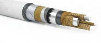
Insulation, armor, protection
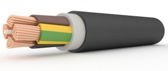
First, let's figure out what armor is, what is protection, and what is insulation. When we talk about insulation material, we mean the material used to insulate aluminum or copper conductors. The purpose of this layer is to prevent the cores from shorting out to each other. Dielectric materials are used here: rubber, polyethylene, PVC, fluoroplastic. Once upon a time, paper was also used, but now this type of insulation is almost never used.
Protective shell (inner) -
placed under the armor or outer protective layer so that they do not damage the insulation and also to increase the degree of protection (from water, temperature, mechanical influences). Not always present.
Cable armor
- These are steel strips (galvanized or not) or braided wire (round or flat). Not all cables have this layer. It is needed to increase mechanical strength. Armored cables are used in places where there is a high risk of damage or there are constant loads. They are used for laying in the ground, on poles, under water, etc. No armor is required for internal wiring - there are no critical loads.
Cable protective layer (outer cover)
- This is the outer sheath that protects the armor and/or conductors. Very often the same materials are used here as for insulation, but the material may differ.
All these three shells come after the designation of the core material, that is, these are the second, third and fourth letters (this is if there is a letter “A”; if there is no letter, the wires are copper). Their designation and decoding are in the table.
| Power cable with PVC (vinyl) and rubber insulation: VVG, VVGng, VVGng-LS, AVVG, AVVGng, AVVGng-LS, VBbShv, VBbShng, VBbShng-LS, AVBbShv, AVBbShng, AVBbShng-LS | |
| Abbreviation | Decoding the abbreviation |
| KG | flexible cable |
| A | (first letter) aluminum core, if absent - copper core by default |
| IN | (first (in the absence of A) letter) PVC insulation |
| IN | (second (in the absence of A) letter) PVC sheath |
| G | lack of protective cover “naked” |
| ng | non-flammable |
| L.S. | Low Smoke - with reduced smoke and gas emissions |
| BB | armored cover made of steel strips |
| Shv | outer cover of PVC hose |
| PVS | P - wire; B - insulation and sheath made of PVC plastic; C – connecting. |
| KVVG | K – control; B - PVC insulation; B - sheath made of PVC plastic; G – naked, lack of protective covers. |
| VVG | B - core insulation made of polyvinyl chloride plastic; B - shell made of polyvinyl chloride plastic; G – naked, lack of protective cover. |
| VVG-ng | B - core insulation made of polyvinyl chloride plastic; B - shell made of polyvinyl chloride plastic; G – naked, lack of protective cover; ng - does not spread fire when laid in groups. |
| SHVVP | Ш – cord; B - PVC insulation; B - sheath made of PVC plastic; P – flat. |
| PPV | P – wire; P – flat; B - PVC insulation. |
| Cable with BPI - cable with insulation made of impregnated paper: ASB, ASBl, ASB2l, AABl, SB, SBl, SBG | |
| A | (first letter) aluminum core, if absent - copper core by default |
| AB | aluminum armor |
| SB | (first or second (after A) letter) lead armor |
| l | Mylar ribbon |
| 2l | double lavsan ribbon |
| G | lack of protective cover “naked” |
| Telephone cable: TPpP, TPpep, TPpPz, TPpePz TPpPBbShp, TPpPzBbShp, TPpePzBbShp, TSV, TSVng | |
| T | telephone cable |
| P | polyethylene insulation |
| P | waist insulation - polyamide, polyethylene, polyvinyl chloride or polyethylene terephthalate tapes |
| E | screen |
| P | polyethylene sheath |
| Z | hydrophobic filler |
| Shp | outer cover made of polyethylene hose |
| WITH | station cable |
| Hanging wires: | |
| A | aluminum bare wire |
| AC | aluminum-steel (the word “steel-aluminum” is more often used) bare wire |
| SIP | self-supporting insulated wire |
| Control cable: KVVG, AKVVG, KVVGng, AKVVGng, KVVGng-LS, AKVVGng-LS, KVVGe, AKVVGe, KVVGeng-LS, AKVVGeng-LS, KVBbShv, AKVBbShv, KVBbShng, AKVBbShng, KVBbShng-LS, AKVBbShng- L.S. | |
| TO | (first or second (after A) letter) - control cable except KG - flexible cable |
| E | screen |
| Some cable types are decrypted in a special way: | |
| KSPV | vinyl sheathed transmission cables |
| KPSVV | fire alarm cables, vinyl insulated, vinyl sheathed |
| KPSVEV | fire alarm cables, vinyl insulated, shielded, vinyl sheathed |
| PNSV | heating wire, steel core, vinyl sheath |
| PV-1, PV-3 | vinyl insulated wire. 1, 3 - core flexibility class (the most applicable core flexibility classes for a given type of wire, however, others can also be used) |
| PVS | vinyl sheathed connecting wire |
| SHVVP | Vinyl insulated cord, vinyl sheathed, flat |
| PUNP | universal flat wire |
| PUGNP | universal flat flexible wire |
| Power cable: NYM, NHMH, NYY, NYCY, NYRGY | |
| N | according to VDE |
| Y | PVC |
| H | halogen-free PVC |
| M | installation cable |
| C | copper screen |
| RG | armor |
| Twisted pair data cable: UTP, FTP, S-FTP, S-STP | |
| U | unfoiled (unfoiled, unshielded) |
| F | foiled (foiled, shielded) |
| S | screened (screened with copper wires) |
| SF | common foil screen + common braided screen |
| SS | foil screen for each pair + common braided screen |
| TP | twisted pair - twisted pair |
| Telephone cable and fire alarm cable: JY(St)Y, JH(St)H | |
| J | installation cable |
| Y | PVC |
| (St) | foil screen |
| Halogen-free flame retardant cable: NHXHX FE 180, NHXCHX FE 180 | |
| N | according to VDE |
| HX | stitched rubber |
| C | copper screen |
| FE 180 | the cable retains its properties for a certain time (in this case 180 minutes) in an open flame, under voltage |
| Mounting wires: H05V-K, H07V-K, N07V-K | |
| H | harmonized wire (HAR approval) |
| N | compliance with national standard |
| 05 | rated voltage 300/500 V |
| 07 | rated voltage 450/750 V |
| V | PVC insulation |
| K | flexible core for fixed installation |
| The Italian-made cable has specific designations according to CEI UNEL 35011: FROR | |
| F | corda flessibile - flexible core |
| R | polivinilclorudo – PVC – PVC insulation |
| O | anime riunite per cavo rotondo - round, not flat cable |
| R | polivinilclorudo – PVC – PVC sheath |
| Cables with XLPE insulation: | |
| N | according to VDE |
| Y | PVC |
| 2Y | polyethylene |
| 2X | cross-linked polyethylene |
| S | copper screen |
| (F) | longitudinal sealing |
| (FL) | longitudinal and transverse sealing |
| E | three-core cable |
| R | round steel wire armor |
| J | the presence of a yellow-green vein |
| O | absence of yellow-green vein |
| Control cable: YSLY, LiYCY | |
| Y | PVC |
| SL | control cable |
| Li | stranded conductor according to VDE |
| SAT - from English. satellite - satellite - cable for satellite television | |
Decoding digital values
After the letters, the cable marking contains several numbers. They reflect the operating voltage for which the cable is designed (if there is no number, then it is used for a 220 V network), as well as the number and cross-section of cores. The first is the quantity, separated by the “x” sign is the section. If all the wires are of the same cross-section, there is only one such pair; if there are dedicated wires for the “zero” (they are of a smaller cross-section), the “+” is followed by a second pair of numbers.
Explanation of the ARNBG cable markings and the main symbols that may appear in these positions
This part of cable marking is not so difficult to understand. Let's look at one example. VVG cables are very popular. The meaning of the marking is as follows:
- copper conductors (the letter “A” is missing in the first position);
- the first “B” is vinyl core insulation (PVC),
- the second “B” is a protective shell, the same PVC,
- D - no outer cover.
This cable is considered by many to be optimal for internal wiring in a house or apartment, since it is relatively inexpensive, comes in many versions, and is produced by a large number of manufacturers.
The numbers indicate the number and cross-section of cores
To better understand the digital designations in cable markings, let’s look at several modifications of this cable product:
- VVG 2*2.5 - two conductors with a cross section of 2.5 mm2;
- VVG 3*4 - three conductors with a cross section of 4 mm2;
- VVG 3*4 + 1*2.5 - three working cores with a cross-section of 4 mm2 and one “zero” - with a cross-section of 2.5 mm2.
The numbers are deciphered in the same way in all other cases.
Temperature conditions and GOST
Few people pay attention to the last part of the cable markings. Here the operating mode (minimum temperatures) and the name of GOST or TU according to which this cable is manufactured are indicated.
Temperature data is important for outdoor cable installation. They are especially relevant for regions with low or high temperatures. Therefore, when choosing a cable type, do not forget about this parameter.
Cable marking: examples of decoding
When studying information on labeling, everything seems quite clear, but when trying to apply knowledge in practice, difficulties often arise. The most difficult thing is that some characteristics are displayed by the absence of symbols. With the first position, everything is more or less simple - the “A” is in front - the wires are made of aluminum, if any other letter is copper.
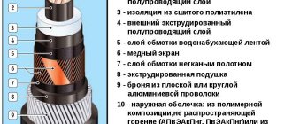
The APvPu2G marking is deciphered as follows:
- A - aluminum conductors;
- Pv - insulation of conductors made of cross-linked polyethylene;
- Pu - protective shell (inner);
- 2G - double waterproofing
Decoding MKESH:
- there is no letter “A” in the first place - copper conductors;
- MK - installation cable
- E - shielded (with aluminum foil);
- Ш - external protection - PVC hose.
As you can see in the example of decoding the MKESH cable, the first position may be the purpose of the cable. Here you can see the following letters:
- G - flexible stranded;
- K - control cable;
- MK - installation cable;
- KSP - transmission systems cable (not power, not used for wiring);
The protective shell and armor may also be missed. They are found in cables that are laid in difficult conditions. That is, confusion may arise here too.
How to navigate? In some cases, by letter. “B” is only the type of armor, “G” is waterproofing, “W” is a protective sheath in the form of an extruded hose. Everything else depends on the situation. But specialists need to study the markings so deeply; a home handyman, basically, needs to know the basic principles, and the specific properties of the cable can be seen in its description. As you can see, cable marking and decoding is not an easy task.
A few more examples of decoding the most popular cables:
VBBShvng:
- there is no letter “A” - copper conductors;
- B - PVC core insulation;
- BB - armor made of two steel strips;
- Shvng - non-flammable external vinyl hose (ng).
AABL:
- A - aluminum conductors;
- A - aluminum shell;
- BL - armor with a backing made of plastic tapes;
KG:
- there is no “A” in front - copper wires;
- K - cable;
- G - naked.
In fact, a CG is just a bundle of copper wires without protective sheaths. Today it is used extremely rarely, but is still found.
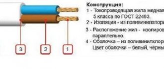
Wire marking
The wires are marked in the same way as the cables. The first position also indicates the core material - A - aluminum, and its absence - copper. The second position can be either P (wire), or PP - flat wire, Sh - cord. In the first case, it can be single-core, in the second, it usually consists of two or three (less often, more) cores. Recently a new type has appeared - heating wires. They are designated PN. And the last - third - position with letters is the insulation material. Everything is standard here:
- B - PVC;
- P - polyethylene:
- R - rubber;
- N - nayrite;
- L - cotton shell, varnished;
- O - impregnated cotton braid;
- M - made of oil-resistant rubber;
But this position may contain information about the design or purpose of the wire:
- G - flexible;
- T - for installation in pipes;
- C - connecting;
After the letters there are numbers. This is the number of conductors (first number) and their cross-section (second number).
Wires - P - regular, round, PP - flat
When deciphering the markings, the main thing is to understand where the cable is and where the wire is. After all, the letter “P” in the second position can indicate polyethylene insulation of wires. You can navigate by the number of letters - the marking of wires usually contains 4 letters, and cables - more. Although this is not an obvious sign, it helps in most cases. But the rest of the decoding of wire markings is much easier than that of cable products. Here are some examples:
APPV:
- A - aluminum conductors;
- PP - flat wire;
- B - vinyl insulation;
PNSV:
- letters A no - copper wires;
- PN - heating wire;
- C - steel core, round;
PV. For wires of this brand, a number is written through a dash indicating the number of conductors in the wire (PV-1, PV-3):
- P - wire;
- B - vinyl shell (PVC).
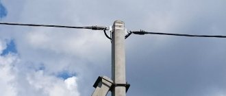
A and AC - uninsulated aluminum wire, AC - twisted.
PR - wire with rubber insulation.
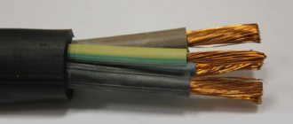
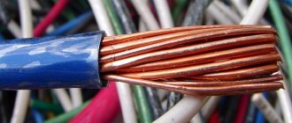
The question often arises: what is the difference between a wire and a cable. Mainly - the number of conductors. The wire most often has one core. Two- and three-core wires differ from cables in that they have only one thin sheath. Cables usually have several of them.
Optical cable marking
Optical cable marking has its own characteristics. The first two letters are OK (optical cable). So there will be no problems with identification. Further, the principle is the same: there is a certain set of notations that encrypt the characteristics. In general, the marking structure after the letters “OK” is as follows:
- Cable laying conditions: G - in the ground
- K - into the sewer
- P - in plastic pipes
- C - self-supporting
- P - suspended
- M - multi-module
- “ng” - non-flammable when laid in groups
- LS - polyethylene, which does not emit halogens, has reduced smoke and gas emissions
- 00 - single-module (no TsSE)
- E1 – single-mode OFF with unshifted dispersion according to ITU-T G.652.B recommendation
Example of a house electrical project
Back
Forward