This introductory article is for those who have already unpacked a dozen or two colored boxes from construction sets with their child, built hundreds of different structures and filled all available containers in the closet with Lego parts. If you are ready to move to the next level: with electronics, microcontrollers, sensors and smart devices, then it’s time to experiment with Arduino!
In this series of articles we will collect the most important things you need to know about Arduino in order to start teaching children yourself. Even if you have never picked up a soldering iron and the words “controller” and “controller” have approximately the same meaning for you, you can be sure that you will still succeed! The world of electronics and robotics today is full of simple and very convenient solutions that allow you to create very interesting projects practically from scratch. Our tutorial will help you quickly navigate and take your first steps.
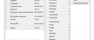
Getting started with Arduino on Windows
If you need to program the device to work with a microcontroller under Windows, you will need:
- any version of the Arduino board;
- USB cable;
- development environment "Arduino IDE".
The latest and drivers are downloaded from the Internet. The board is connected to the computer via a cable. The settings indicate the type of Arduino board with which the programmer is working.
Drivers and development tool are installed. You can open suitable examples of work and create your own applications based on them.
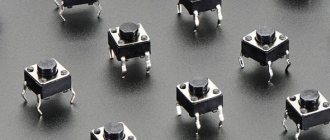
#37. Connecting a 4x4 Arduino matrix keyboard
Today in the lesson we will look at the principle of operation of a 4x4 matrix keyboard . Let's connect a 4x4 keyboard to the Arduino and write a sketch to get values when pressing the buttons .
Technical parameters of the matrix keyboard for Arduino.
Updated: October 19, 2022 Read more...
Features of working with Arduino Mini
Working with Arduino Mini follows the same rules as with other boards, with a few exceptions:
- connecting Arduino Mini to a PC is more difficult than standard models;
- in the IDE settings you must manually specify the board type from the Tools | Board and select “Arduino Mini”;
- Flashing a new sketch into the Arduino Mini begins with physically pressing the reset button on the board right before starting the operation.
Even children can learn to program and work with this controller. The integrated environment provides a simple and logical interface.
Brief information about Arduino Mini
This version of the microcontroller must provide minimal dimensions while maintaining other functions, which imposes some features on the board:
- The microchip in Arduino Mini (ATmega328 is used) is smaller in size.
- It has 2 additional analog inputs, 8 in total. However, 4 of them do not have pins on the board. For them, you need to solder the output pins yourself. 2 pins are used for the I2C interface and the Wire library.
- The strength of Arduino Mini is less than other boards from the manufacturer.
- ATmega328 is soldered into the board and therefore not removable; the entire microcontroller must be replaced.
- Cannot withstand voltage overloads at inputs above 9 V.
#36. GSM module SIM800L. AT commands and sending SMS
Today in the lesson we will look at the GSM GPRS SIM800L V2.0 MicroSIM module with antenna . Let's see what its advantages and disadvantages are. Let's figure out how to control this module using AT commands and send a CMC message .
GSM GPRS module has minimal functionality - data exchange with the GSM module via UART. The board has a slot for installing an external SIM card. SIM800L V2.0 GSM/GPRS is a quad-band GSM/GPRS module compatible with Arduino. The module is used to implement GSM and GPRS functions. The advantage of this module is the ability to directly connect it to an Arduino or other microcontroller with a 5V supply voltage.
Updated: September 15, 2022 Read more...
Main functions
The programming language used in Arduino IDE is a truncated version of C++. The main functions used to organize the operation of the microcontroller are divided into groups, which are:
- carry out signal input and output in digital form;
- control input and output of analog signal;
- provide additional input and output control capabilities;
- manage time;
- carry out mathematical calculations and functions;
- carry out calculations in trigonometry;
- provide random numbers;
- carry out operations with bits and bytes;
- provide calling external interrupts;
- generate a microchip interrupt.
What is a sketch and its functions
A program (function in C++ terms) that has a given structure and is intended for the Arduino platform is called a sketch. The sketch retains a lot from C++:
- syntax - semicolon is used as a line separator;
- integer constants - declared in header files;
- use of language constructs switch case, else if.
When power is applied, the bootloader, stored in non-volatile memory, is launched and transfers control to the user sketch.
The sketch structure includes two required functions:
- setup();
- loop().
When control is transferred to a sketch, the setup() function is called first, and only once. Thus, this function is always executed when voltage is applied to the microcontroller. It should include tasks for initializing variables, setting pin modes and associated sensors and equipment. When setup() completes, the loop calls the loop() function, which runs until the power is turned off.
It is better to teach beginners how to program freeduino microcontroller boards using examples of simple applications. An illustration of the use of these functions will be a sketch that controls an LED, an analogue of the classic “Hello, World!”
| 1 2 3 4 5 6 7 8 9 10 11 12 | void setup() { pinMode(14, OUTPUT); // Set pin 14 to pin } void loop() { digitalWrite(14, HIGH); // apply voltage, turn on the LED delay(500); // delay 0.5 s digitalWrite(14, LOW); // turn off the LED delay(500); // wait 0.5 s } |
void setup() { pinMode(14, OUTPUT); // Set pin 14 to pin } void loop() { digitalWrite(14, HIGH); // apply voltage, turn on the LED delay(500); // delay 0.5 s digitalWrite(14, LOW); // turn off the LED delay(500); // wait 0.5 s }
To get started, you need to upload the sketch to the microcontroller. Launch the Arduino IDE and copy or type the sketch. To transfer, select the environment menu item “Fill”. In this case, the program is compiled and translated into machine code. There is no need to delete previous uploaded sketches - everything happens automatically. Restarting Arduino will cause the sketch to work and the LED on the microcontroller to blink.
If this sketch seemed like a useless demonstration toy, then it is not. Let's make some small changes to the sketch:
| 1 2 3 4 5 6 7 8 9 10 11 12 13 14 15 16 | #define PIN_RELAY 5 // This line can be placed in a separate header file. // it defines the pin to which the relay control signal will be output void setup() { pinMode(PIN_RELAY, OUTPUT); // the relay pin is declared to work as an output digitalWrite(PIN_RELAY, HIGH); // Turn off the relay with a high signal } void loop() { digitalWrite(PIN_RELAY, LOW); // Turn on the relay with a low signal delay(5000); // pause for 5 s digitalWrite(PIN_RELAY, HIGH); // Turn off the relay with a high signal delay(5000); // delay 5 s } |
#define PIN_RELAY 5 // This line can be placed in a separate header file.
// it defines the pin to which the relay control signal will be output void setup() { pinMode(PIN_RELAY, OUTPUT); // the relay pin is declared to work as an output digitalWrite(PIN_RELAY, HIGH); // Turn off the relay with a high signal } void loop() { digitalWrite(PIN_RELAY, LOW); // Turn on the relay with a low signal delay(5000); // pause for 5 s digitalWrite(PIN_RELAY, HIGH); // Turn off the relay with a high signal delay(5000); // delay of 5 s } Pay attention to the syntax of the language used, which is exactly similar to C++, and the way of using ready-made functions.
Arduino, Raspberry Pi
Arduino
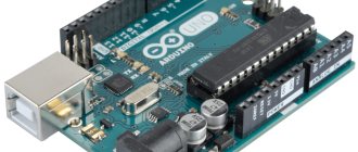
— a hardware platform for device development, with an I/O board and a simple development environment on Processing/Wiring. Based on the Atmel AVR (ATmega) microcontroller, most boards are programmed via USB. Arduino boards allow you to create various devices with your own hands and are a good tool for beginners and learning MK. Most devices can be assembled without even using a soldering iron! In this section you will find various interesting circuits and projects for the Arduino platform, their clones Freeduino, Seeeduino, as well as Raspberry Pi, Python boards, etc. Don't forget to visit the Arduino forum
- Inexpensive DIY thermal imager
- Solar tracker
- Face recognition and tracking system
- Intervalometer with LCD for Sony NEX
- PTZ webcam controlled by Arduino
- Ethernet camera based on Arduino
- A simple timelapse camera using a Raspberry Pi
- 3D Photo Turntable Upgrade
- Battery capacity meter (Li-Ion/NiMH/NiCD/Pb)
- Simple Li-ion battery capacity tester
- Measuring Capacitance of Capacitors Using Arduino
- Arduino based inductance meter
- Winding machine on Arduino
- Winding machine on Arduino version 2.0
- Water flow meter
- Tachometer on Arduino
- Measuring the current consumption of devices using current sensors of the ZXCT series
- Real-time power consumption monitoring using Arduino and LabView
- Display to show the frequency of the power supply
- Digital voltmeter on Arduino with connection to PC via serial port
- 4-channel voltmeter with LCD indicator based on Arduino
- DIY parking sensors
- Bicycle speedometer on Arduino
- How to text a heater?
- Launch and assembly of the M590E GSM module
- GPS tracker for cars with sending data to the server using a GSM/GPRS shield
- Cat collar with GPS navigation based on TinyDuino microcontroller
- Portable compass TinyCompass
- Text display for remote communication with the office based on Arduino Uno
- Smart refrigerator magnet based on Arduino
- Seismic activity monitoring device
- Barometer with advanced features
- DIY barometer
- Contactless temperature control with RFID access for employees with data sent to the LORAWAN cloud
- DIY IR thermometer
- Infrared motion sensor (PIR sensor)
- Automatic lighting AtMega328 (PIR)
- Autonomous LED spotlight on Arduino
- Complex about simple things: digital thermometer
- Thermal relay with NTC resistor
- Arduino, motion sensor and relay module
- Homemade anti-theft device based on Arduino and fingerprint sensor
- GSM security system for home based on Arduino
- Radio Frequency (RFID) Access Control Using Arduino UNO and EM-18 Module
- Electronic visitor registration system
- Morse code decoder and transmitter on Arduino
- Receiving a signal from multiple 433MHz transmitters on Arduino
- Radio on Arduino
- Audio player on Arduino
- Smart home with Arduino
- Home weather station server on Arduino + Android widget for data output
- Home weather station server on Arduino + Widget on Android. Adding a BMP085 sensor
- Home weather station server on Arduino - widget for OS X
- Weather station on Arduino and MR3020 for public monitoring
- Reading the temperature sensor DS18B20
- Weather station on Arduino with wireless temperature sensor
- Arduino: Making your own temperature sensor
- Weather station + plotting + C#
- IoT barcode scanner with results sent to the cloud
- Sending data from an IoT device via the LORAWAN network to The Things Network service
- Covid-19 coronavirus data monitoring
- Fallout style Vault Keeper climate monitor on ESP8266
- Temperature and humidity sensor using ESP8266 Wi-Fi module
- WiFi ESP8266. Nodemcu Lua for ESP-01. Load management via web interface
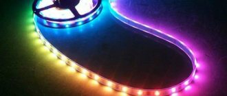
- Setting RGB LED Strip Color Using Capacitive Touch Disk Pad
- NodeMCU - a quick start for Arduino lovers
- WeMos D1R2
- Connecting Arduino to the Internet: setting up client-server mode, processing GET and POST requests
- Sending data from Arduino to server (ENC28J60)
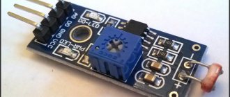
- Ambient air pollution detector
- MQ-2 Gas Sensor Module and Arduino Connections
- Resistive pressure sensor FSR402
- DDS sine wave generator
- Signal generator on Arduino
- LCD oscilloscope on Arduino
- Connecting the Bluetooth module to Arduino
- Transfer data via Bluetooth between Android and Arduino
- Controlling lamps via smartphone
- Control system for 220V appliances from a smartphone
- Internet of Things with RemoteXY
- Internet of Things with RemoteXY: Connection Configuration.
- Internet of Things with RemoteXY: working with the online editor and interface design elements
- Internet of Things with RemoteXY: Controls, Part 2
- Internet of Things with RemoteXY: display elements
- Internet of Things with RemoteXY: Controls
- Smart socket using a kettle as an example
- Arduino as an HID device
- Transferring MIDI data to a computer
- USB MIDI controller on Arduino
- Capacitive touch Midi keyboard
- Mini synthesizer on Arduino using a buzzer
- A simple clock based on gas-discharge indicators, optocouplers and Arduino
- Clock on Arduino using a standard indicator
- Setting up an RTC real-time clock module for Arduino
- Arduino clock from customer display (VFD)
- Clock on Arduino
- LED clock on Arduino
- O-Clock – a simple alarm clock based on Arduino and an 8x32 matrix indicator
- Countdown alarm clock on Arduino with Nokia 5110 display
- Universal 8-channel timer on Arduino
- OLED i2c display 128x64 pixels
- Color OLED display 96x64 pixels
- Arduino and dynamic indicators
- DIY Ambilight
- Dynamic backlight for TV
- RGB LED Piano Lighting
- JoyLED - non-standard RGB LED control
- Controlling an LED strip using a TV remote control and Arduino
- LED disco floor on Arduino
- Game TV console on Arduino. Part 1
- Game TV console on Arduino. Part 2
- Tetris based on Arduino and two-color LED matrices
- Button controller for the game What? Where? When?
- "Smart dumbbell"
- GTO in a modern way
- Logic game Crossing on Arduino
- Arduino toy: Simon said
- Dice game on Arduino
- Unusual control of LED (and other) matrices on Arduino and 74HC585
- New Year's magic or magic box on Arduino
- Sports counter on Arduino
- Passage sensor on arduino
- Digitizer for arduino uno
- Controlling the camera, devices and data from sensors on the TV screen
- TV output on Arduino
- VGA on Arduino
- Unusual combination lock on Arduino
- Arduino code lock
- A safe that recognizes colors
- Brute Force PC BIOS using Arduino
- Automatic watering for indoor plants using Arduino
- Automatic temperature and humidity controller for pets based on Arduino
- SMART-GARAGE
- Frozen pipe alarm on Arduino
- The simplest call with two melodies
- Singing plant based on Arduino
- Rotating platform with adjustable RGB lighting and Bluetooth control
- Playing WAV Files Using Arduino
- Audio spectrum analyzer on RGB tape WS2812
- Audio Spectrum Analyzer
- 3x3x3 LED cube
- LED cube 4x4x4
- LED cube 5x5x5
- LED Cube 8x8x8 on Arduino with RTC
- LED cube brightness control
- Holographic clock on Arduino
- Simple POV display based on Arduino
- LED matrix 24×6
- 3D input interface on Arduino
- Touch control panel
- Makey Makey New Year's RGB garland control
- Apple Remote Shield on Arduino
- Arduino laser tag
- Controlling iRobot Create with a Wireless Gamepad via Arduino
- Development of an Arduino extension for mobile robots
- Sending data from Arduino to WEB server with a GET request
- We control any remote control equipment at home via IR from a web page
- Sound activated socket
- Voice control of UNIEL radio sockets
- Hand controlled RGB night light
- LANp – RGB lamp from scanner parts controlled via network
- Light dimmer controlled by Arduino
- AC dimmer on Arduino
- Light measurement on Arduino and display on Nokia 5110
- Day-night controller based on Arduino
- Battery controller for arduino
- Power supply for Arduino from ATX
- ATX power supply controlled by Arduino
- Single-phase frequency converter on Arduino
- DIY Arduino with USB port
- Nanino - homemade Arduino
- Making your own Arduino Uno Mini
- EGYDuino – DIY Arduino clone
- Homemade Arduino-compatible debug board on a budget MK ATmega88/168/328
- Quick start with Arduino - Arduino UNO R3 development board
- Arduino Pro Mini and UniProf
- Development board with ATmega328 microcontroller
- Bitlash shell on Arduino
- Developing a brainfuck interpreter on Arduino
- Program Arduino using your Android device!
- DIY hive scales
- Automatic feeder for aquarium
- Connecting the coin acceptor to Arduino
- Vending change machine on Arduino
- Connecting a PS/2 keyboard
- Mini USB keyboard on microcontroller
- Wake up PC over network on Arduino and ENC28J60
- Write and read to SD card
- Connecting I2C EEPROM to Arduino
Arduino tutorials
- Arduino IDE - Introduction (video tutorial)
- Arduino UNO Lesson 1 - LED Control
- Arduino UNO Lesson 2 - Servo Control
- Arduino UNO lesson 3 - Timing
- Arduino UNO lesson 4 - Running fire
- Arduino UNO Lesson 5 - Fade
- Arduino UNO lesson 6 - Encoder
- Arduino UNO lesson 7 - Piezo emitter
- Arduino UNO Lesson 8 – Night Light
- Arduino UNO Lesson 9 - Managing a Powerful Load
- Arduino UNO Lesson 10 - LCD
- Arduino UNO Lesson 11 - Serial LCD
- Arduino UNO lesson 12 - Joystick
- Arduino UNO lesson 13 - Connecting the L298N motor driver
- Arduino UNO lesson 14 - Connecting the HMC5883L digital compass
- Controlling a bipolar stepper motor without using a driver
- Arduino Uno. Connecting the IR Receiver
- Connecting a seven-segment indicator (1 digit) to Arduino via SPI
- Shift register 74HC595
- Connecting an 8*8 LED matrix to Arduino via shift registers
- Arduino String object and serial commands
- Monitoring the position of the contacts of a 3-position switch using Arduino
- Text menu on Arduino for 20x4 display
- Arduino: thank you and goodbye
- Android and Arduino. Introduction to ADK
- Android and Arduino. Software
- Android and Arduino. Hello Arduino from Android
- Android and Arduino. Hello Android from Arduino
- Android and Arduino. Two-way data exchange
- Arduino World Young Fighter Course
- Arduino Course - Sensors
- Arduino Course - Logic
- Arduino Course - Serial Monitor
- Arduino Course - Displaying Data on LCD
- Arduino Course - Sound
- Arduino Course - Motors
- Arduino course - Microcircuits
- Arduino Course - Time and Random
- Arduino Course - Interrupts, Function Creation, Tips
- Arduino Course - Modules
- Arduino Course - Rangefinders
- Arduino - Processing course
- Control system for indoor plant parameters
- Temperature and relative humidity logger on chipKIT Uno32
Raspberry Pi and other boards
- Raspberry Pi 4 and Intel Neural Compute Stick 2
- Using Raspberry Pi GPIO Pins
- Z-wave smart home elements on Razberry and Z-Uno. Part 1
- Z-wave smart home elements on Razberry and Z-Uno. Part 2
- Raspberry Pi GPIO Web Control
- Raspberry Pi as an FM transmitter
- Raspberry Pi FAQ
- Raspberry Pi, Raspbian, XBMC and 7" eGalax touchscreen
- Hi-Fi player on Raspberry PI using RuneAudio software
- Double whammy: AirPlay-Pi and new life for an old radio
- FM radio broadcast station on Raspberry Pi
- Media center on Raspberry Pi 2
- Forex quotes board in real time on a 32×64 RGB matrix
- LED display controlled by a Raspberry Pi minicomputer and WiFi adapter
- LED display measuring 128x32 pixels, controlled by a Raspberry Pi microcomputer
- Portable laptop based on Raspberry Pi
- Plotter on Raspberry Pi using components from CD-ROM
- Connecting NES/Dendy console joysticks to Raspberry Pi
- A Raspberry Pi-powered chest that recognizes your face
- Music and light harpsichord on Intel Galileo
- Photo studio for Barbie dolls
- Using HMI TFT display STONE and ESP32 to control a massage chair
- Servo drive control using HMI LCD screen and STM32
- Mini-computer M5StickC on ESP32-PICO module
- MAIXDUINO Development Board for AI + IoT Applications
- Introducing the MicroPython Board
- 10 miniature development boards to solve any problem
- FEZ and .NET Micro Framework
- Particle Photon
- DFRobot Curie Nano
- Latte Panda
- FEZ Panda II Review
- Netduino: Interfacing with Character LCD Display
How digital pins work
The digital outputs have the ability to enable or disable pull-up resistors. They are controlled programmatically.
The pins can provide quite a large current (up to 40 mA). This value is enough to connect an LED or other electronic device, but is not enough for most electromechanical devices such as relays, solenoid, motor.
Under heavy load, the protection in most cases manages to operate and turn off this controller leg. It is recommended to connect the outputs via 470 Ohm or 1 kOhm resistors if there is a need to provide the maximum possible current.
#35. We display symbols on the LCD 1602 and LCD 2004 display.
, LCD 1602 and LCD 2004 displays are often used. How to connect LCD 1602 to Arduino was discussed in the previous lesson. In addition to text, you often need to display special characters . For example, the designation of temperature is degrees Celsius or percentage of humidity , as well as the direction of advancement or rotation . How to display special characters on the LCD 1602 and LCD 2004 display ? In this lesson, we will look at the output from a set of preset symbols and create our own symbols , which we will also display on the LCD 1602 and LCD 2004 .
Updated: July 8, 2022 Read more...
Nuances of analog inputs
The analog output signal is provided by the ADC. Atmega chips use a six-channel ADC. Its resolution is 10 bits or values from 0 to 1023. The main purpose of the inputs is to read the signal of analog sensors.
The Arduino pins corresponding to the analog inputs are numbered 14 to 19. The analog input pins can connect pull-up resistors, which work the same way as the digital pins. The resistors are turned on using the command: digitalWrite(14, HIGH); // enable resistor on analog input pin 0
If you controlled the output by setting the mode, then before subsequently changing its functions, reset the parameters to avoid incorrect operation. When using analog inputs, you should pay attention to working with serial wire, an auxiliary data transmission channel.
Memory in Arduino
The ATmega168 microcontroller used on Arduino platforms uses three types of memory:
- flash - used to store sketches;
- RAM - random access RAM;
- EEPROM - non-volatile.
Flash memory and EEPROM retain data when power is turned off. RAM is losing information. The ATmega168 microcontroller is equipped with:
- 16 KB flash memory (2 KB used to store bootloader);
- 1024 bytes of RAM;
- 512 bytes EEPROM.
A small amount of RAM, with a large number of rows, can be completely used up.
If there is no free space in RAM, the program crashes. There are several ways to solve the problem:
- some data is stored on a computer, the user periodically accesses the data there or saves it there;
- for large arrays, reduce the size of the operated data, for example, replace the Int type with the Byte type;
- Move constants outside of RAM and store them in flash memory.
Work with EEPROM is carried out using a specialized library.
Reflashing the controller
The algorithm for flashing the controller is approximately the same for all circuits; even children can figure it out. Let's consider, as an example, working with Atmega8U2 for Mega2560:
- download the “FLIP” program from the Atmel company website (atmel.com);
- the latest firmware version is downloaded;
- a jumper or, better yet, a 10 kOhm resistor closes two contacts on the back of the board;
- Arduino connects to a PC via USB;
- the two reset contacts of the controller close for a few seconds;
- drivers are installed for the device detected by the PC;
- The FLIP program starts, select “File->Load HEX File” in the menu and load the new firmware;
- in the menu look for “Device->Select”, then select “at90usb82” from the list;
- select the open command in “Settings→Communication→Usb-Open”;
- check the settings of the parameters and start burning “Run”;
- remove the resistor jumper from the board.
Flashing is completed, the device is ready for use.
Creating Libraries
A programmer can create his own libraries for Arduino so as not to write repeated pieces of code from scratch. They are convenient for collecting training algorithms and providing unchangeable visual graphic content. It all starts with developing a sketch that performs the required tasks. After this, you need to determine which part of the code should be transferred to the library. Next, we begin the process of converting the sketch into a library, which consists of two files:
- header with extension .h;
- with code and extension .cpp).
The first gives an explanation of the contents of the library. It includes a list of functions, objects, variables that the library uses. Despite the light version of C++, the library can use object visibility attributes, classes, constructors and destructors, and other OOP features. Headers use C++ language directives. The library is not placed in a special module and is stored in text form, in .cpp and .h file format in a separate folder with the name of the library, but located in the libraries directory. Text files are compiled using the specified library.