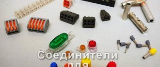
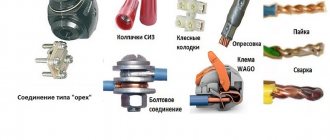
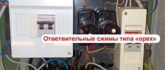
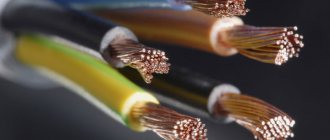
When installing electrical wiring, especially in distribution cabinets, it becomes necessary to organize the wiring. Terminal blocks are used for this.
In addition to accuracy and safety, this installation method makes it possible to quickly disconnect the selected line at any time (for example, for repairs), without the need to de-energize the entire system. There are different types of electrical terminal blocks, but certain standards must be followed in their production. The rules for the construction of electrical installations require that GOST 17557–88 “Lighting terminal blocks” be followed. There are other standards, including international ones (ISO, IEC, ITU, SA, CE and others).
Important! When selecting equipment, make sure that you have a manufacturer’s certificate. Information can be requested from the seller (in the technical documentation), or see the markings on the case.
Compliance with standards is necessary not only to comply with PUE standards, your safety depends on it.
Basic requirements for the design of terminal blocks
One way or another, the requirements for reliability and electrical characteristics are specified in various standards.
- Heat resistance is determined by the material of the supporting body. It must be non-flammable. During operation, contact groups can heat up to high temperatures (especially if the contact is poor or the permissible load is exceeded). In this case, there should be no source of combustion.
- When heated, the housing should not change its strength characteristics. If thermal gaps do not ensure retention of contact groups in the mounting sockets, such products cannot be used.
- Protective covers (if any) are not necessarily made of non-combustible materials. However, the material must not support combustion.
- The strength characteristics should ensure that the terminals are fixed under normal force (when the screw clamps are tightened, the plates remain in place).
- Any types of clamps provide reliable fixation of wires without preliminary preparation (tinning, using lugs, forming rings).
- The length of the contact plates prevents contact between the inserted conductors. This is done to counteract galvanic corrosion (eg copper + aluminum).
- The marking should contain information about the diameter of the conductors, the type of current, and the maximum voltage value.
Permanent connection
This installation method is performed in the same way as using a bolt and nut, but using a special tool - a riveter. The operating principle of the riveter lies in the rivet design.
It is a hollow aluminum tube with a thickening at one end. A metal rod with a head is inserted into the rivet. When the rod is pulled through the rivet, it forms a bulge at the other end of the rivet, while simultaneously expanding the tube itself somewhat.
When a certain maximum force is reached, the rod breaks off, leaving a clean, formed rivet. If you do not take into account the cost of the tool, the price of an individual rivet makes this type of installation the cheapest after twisting. There is only one drawback - such a connection is disposable and permanent.
Another option for permanent connections is obtained by using special tinned copper connecting tubes. Such tubes are produced in several diameters to suit the most common diameters of the wires being connected.
The stripped ends of the wires are inserted into the opposite ends of the tube and the latter is crimped with a special device. Together with twisting, this is the most compact type of connection of conductors.
This method can be used only if the diameter of the wires is the same and exactly matches the diameter of the tube.
Types of terminal blocks according to housing material
At a minimum, the supporting part is made of dielectric. Based on its characteristics, the manufacturer selects the minimum permissible distances between the terminals to prevent air breakdown.
- Ceramics. This material has a lot of advantages, and, perhaps, one drawback: it is fragile. The ceramic terminal block is used in electrical installations with intense temperature conditions: heating devices, powerful power busbars (natural heating of the conductor is allowed). In addition, ceramics are used when organizing wiring near mechanisms that have a high operating temperature. The only limitation is that there should be no vibration or shock loads in the places where ceramic terminal blocks are installed.
- Polypropylene. Durable, relatively plastic material. It resists shock loads and vibration well and does not crack when deformed. However, its temperature and dielectric characteristics do not allow use in high-voltage networks with neutral and phase wires located nearby. Therefore, polypropylene products are usually used on one line (either zero or phase), and are limited to 600 volts.
Another application is terminals for connecting household lighting devices. In such blocks, zero and phase can coexist.
- Polyamide. Durable, non-flammable material with excellent characteristics. At the same time relatively expensive. Used in pads that have high performance requirements. Due to its resistance to external influences, polyamide can be used both in load-bearing elements and in the manufacture of a durable outer casing.
- Carbolite. Perhaps the best non-flammability characteristics, and the dielectric of this material is good. Withstands static loads and vibration, but may crack upon impact. Carbolite terminal blocks are used in any electrical installations, except for heating elements. Except that the cases they make are not very durable.
Carbolite blocks are widely used in household lighting equipment. Almost every second chandelier is connected using such a switch.
- Polyvinyl chloride (PVC). Blocks for mass use for low-current connections. Again, household appliances and lighting. The material is non-flammable, quite durable, but deforms when heated.
The main advantage is the low price. For this reason, many unscrupulous electricians use these blocks for other purposes when assembling powerful electrical installations. Such “savings” often lead to breakdowns of switchboards and electrical equipment failures. In addition, such pads are available in a convenient form factor: the line can be easily divided into the required number of contacts.
- textolite and ebonite are also used . But these are piece products for certain projects: the material is too expensive.
Rules for choosing self-clamping terminals
The main rule for a potential buyer of self-clamping terminal blocks is, perhaps, the mandatory verification of the product for authenticity. There are a lot of counterfeit goods on the commercial market, marked with the German brand - the manufacturer Wago itself warns about this.
The cost of such products is reduced, which naturally attracts the buyer. However, this kind of savings can result in troubles when operating the assembled circuits.
Meanwhile, without unnecessary warnings, it should be obvious that a counterfeit product is a significant reduction in quality. How to choose the right wire connectors without fear of getting a fake? In principle, everything is quite simple. You just need to be more careful when choosing self-clamping terminals for installation.
A branded product traditionally has the Wago logo printed in a clear font, usually on the top or side of the case. Also on the side are the main parameters - voltage and current.
This is what a branded product released under the Wago brand looks like. Counterfeit terminal blocks, as a rule, do not contain such a seal, or contain a partial one applied with low quality
The color of the insulating material of branded products is distinguished by a uniform, clear color. There is a mini connection instruction on the back/side of the terminal block.
When compared with Chinese counterfeit goods, terminal blocks, as a rule, do not have any of the above-mentioned differences. In addition, the fake is immediately distinguished by the blurred color of the insulator, often multi-colored.
Of course, the main points of choice are the purely technical parameters of self-clamping terminal blocks. In particular, the operating voltage and permissible conducted current.
If the mounted circuits are designed for operating voltages that exceed the capabilities of the terminal blocks, then the application becomes impractical and, moreover, dangerous.
You will learn about the color of the connected wires from the following article, the contents of which we recommend that you familiarize yourself with.
Types of terminal blocks according to the method of fastening the conductor
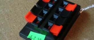
- Screw terminal blocks are available in two form factors: classic plug-in and clamp .
- The classic ones are a screw-nut connection. The contact plate itself acts as a nut. An unprepared conductor is not suitable for such a block: it is necessary to install a terminal at the end, or form a ring. They are mainly used in distribution boxes for wiring indoors.
A more advanced design has a pressure washer-plate under which the unprepared end of the cable can be inserted.
- Clamping blocks are presented in the form of a fixed clamp in which the cable is clamped using a screw:
or in the form of a movable clamp, which is tightened with a screw to the contact pad.
A significant drawback is that the conductor is under pressure and can be deformed (especially for aluminum conductors). As a result, the contact weakens. Such pads need to be tightened at least once a year. Screw connections can also become loose due to vibration.
- Quick-release terminals do not have the disadvantages of a screw connection; the ends of the conductors are attached more securely. The most widely used products are from WAGO; in fact, this is the name given to any pads of this type. Also available in two versions:
- PUSH WIRE (one-piece disposable). When the wire is inserted into the hole, it is clamped. It is impossible to remove it from there: the block will be destroyed.
At the same time, the contact is more reliable than on reusable terminal blocks. They are used after careful checking of the correct cable routing. For possible correction, it is recommended to leave a margin of a few centimeters of wire.
- CAGE CLAMP (reusable). The conductor is clamped using a lever. The advantage is that the contactor can be reused. Disadvantage: the clamping mechanism cannot provide reliable contact.
- Nevertheless, such blocks are quickly gaining popularity, especially among electrician teams involved in connecting apartment buildings.
How it works?
The presented photographs of the terminal blocks show that their design is surprisingly simple: in the cells of the plastic case there are brass tubes with threads on each side. Fixation occurs through tightening screws, pressing or another method of fastening, depending on the type of block.
The principle of operation of the terminal block is to connect a pair of conductors by inserting the cores inside the tube and fixing them. Compared to other options for fastening wires (soldering, twisting, welding), the terminal has some advantages:
- No need for additional tools and materials;
- Quick and easy installation;
- Possibility of fastening short wires;
- Reliability and durability;
- Possibility of connecting aluminum and copper conductors.
However, it is important to take into account the operational features. For example, the terminal block may only be installed in a panel or distribution box, and its placement inside walls is unacceptable.
It is not recommended to use terminal blocks to connect multi-core wires, as their unity can be disrupted or not all the wire can be clamped due to uneven pressure or uneven surface.
Types of terminal blocks by contact arrangement
The simplest block is a metal strip with a series of contact clamps. Designed to combine multiple wires with the same rating. For example, zero bus or grounding.
The main wire comes to one of the screw terminals, and the entire block acquires the necessary potential.
The feed-through type is designed for linear connection of wires. Often used for splicing different metals (copper and aluminum).
There is another type of feed-through terminal block.
The main principle is that parallel conductors are separated by a dielectric.
Barrier blocks are similar to pass-through blocks, but they provide more reliable protection against short circuits of adjacent wires. The dielectric extends beyond the contact plane and additionally protects the block from accidental short circuit (for example, a conductive element falling onto the terminals).
Installation features
Connecting wires and cables using a terminal block is quite simple and does not require any special skills. The required block with a cell of the most suitable size is selected, after which the cores are inserted inside, clamped with screws.
First, the insulation is removed from the ends of the cores at a distance of 5-7 mm, after which the entire conductive surface is thoroughly cleaned. If necessary, multi-section blocks are cut into the required number of segments. It is not recommended to clamp aluminum wires into screw devices, since such wires can be crushed by the screw.
Where can I buy
You can purchase pads as quickly as possible at your nearest specialty store. The optimal option, in terms of price-quality ratio, remains purchasing from the AliExpress online store. Mandatory long waits for parcels from China are a thing of the past, because now many goods are in intermediate warehouses in destination countries: for example, when ordering, you can select the “Delivery from the Russian Federation” option:
| UKK 80A Din Rail Terminal Blocks | Din rail with terminal block 10 pcs. | DIN rail terminal block |
| 10pcs Black Din Rail Terminal Blocks | Terminal blocks for din rail PT-2.5 | 30/50/100 pcs. push terminal block |
What are terminals?
Terminal clamps are electrical devices used to connect cables and wires. The design of the terminals includes 2 or more contacts made of conductive metal, equipped with fastenings for conductors. The terminal block housing is made of dielectric material to prevent short circuits or electric shock.
Conducting plates are made of copper or copper-based alloys. The minimum resistance is ensured by tinning, that is, coating the plate with a layer of tin or tin alloys. Varieties of terminal blocks are equipped with springs; a copper plate is in contact with the wire; the spring itself is usually made of chromium-nickel steel.
Plastic or porcelain is used as the insulating material of the housing. The material is selected taking into account resistance to deformation and high temperatures. The use of terminal blocks in installation has become widespread, and gradually soldering of wires fades into the background, giving way to terminal connections. Using terminals is more economical than soldering and is significantly more reliable. The terminals have proven their effectiveness in connecting wiring with copper and aluminum conductors, providing a high-quality connection and protecting the cable from mechanical stress during installation.
RCD connection diagram: instructions, methods, errors
What is an RCD in electrical engineering: types, principle of operation
RoHS and REACH
RoHS (Restriction of Hazardous Substances Directive): The materials used in the connection blocks comply with EU Directive 2015/863, Annex II as amended by Directive 2011/65.
Certificates issued by an accredited independent laboratory are available upon request.
REACH (EU technical regulation "Procedure for state registration, examination and licensing of chemical substances"): the materials used in the connection blocks comply with the EU REACH Directives, according to the Directive of June 2022, adding 173 substances SVHC (Very Highly Hazardous Substances) to the list, published by ECHA on 12 January 2022, applicable under REACH Directive 1907/2006. Certificates issued by an accredited independent laboratory are available upon request.
Halogen-free and halogen-free
According to the International Electrochemical Commission (IEC 61249-2-21 Restricted Use of Halogen for Electronic Circuits), for a substance to be classified as halogen-free, it must contain less than 900 ppm of chlorine or bromine or less 1500 ppm halogens.
Halogen elements
is any of the six nonmetallic elements that make up group 17 (group VIIa) of the periodic table. These are fluorine (F), chlorine (Cl), bromine (Br), iodine (I), as well as rare and recently discovered elements astatine (At) and tennessine (Ts). The most common are chlorine and fluorine, found in PVC, Teflon and its derivatives, and bromine, used in plastics as a flame retardant additive. The disadvantage of these products is that they release toxic fumes when ignited. In addition to the risk to people, they also emit corrosive gases that are harmful to electrical and electronic equipment. Among the flame retardants used in plastics, polychlorinated biphenyls (PCBs) and polybrominated biphenyls (PBBs) have adverse effects on the environment and people due to their persistence, toxicity, and bioaccumulation.
When exposed to extreme thermal stresses, which can occur during a fire, brominated flame retardants (BFRs) can form halogenated dioxins and furans.
PBBs and PBDEs (polybrominated diphenyl ethers) are currently banned in Europe by the WEEE (Waste Electrical and Electronic Equipment) and RoHS Directives.
Materials provided by https://ultimheat.com/
Installing a radio
Standard devices do not always satisfy the requirements of users, so they are replaced with radios selected to suit their taste.
Car radio installation
Previously, installing a radio caused quite a lot of problems, due to the fact that each manufacturer, be it the expensive Pioneer or the cheap Saundmax, used their own connection standards, and you had to cut into the car wiring diagram to install the connector. Recently, there has been standardization in this process; many manufacturers are introducing the so-called euro feature.
Radio socket
That is, you need to connect the mating part to the car circuit once and then simply remove the radio tape recorder and install another one. If you purchased a fairly “new” car, then this connector may have already been installed by the manufacturer. if it is not there, then it’s okay, the work of installing it is not particularly difficult, you can do without the services of an auto electrician, spending a couple of hours and doing everything yourself.
Car radio connectors
Maximum change in tensile strength with temperature
Comparison of changes in tensile strength of copper, brass UZ34Pb2, SPCC steel, AISI 304 stainless steel and nickel 201 according to maximum exposure temperature maintained for 90 minutes (% of value measured at room temperature)
Copper and steel gradually lose mechanical strength, retaining only about 50% at temperatures around 900° C. Brass remains relatively stable, but reaches a melting point just before 900° C. Stainless steel 304 and nickel 201 do not show significant changes in mechanical strength up to 900 °C.
Clearances and creepage distances
Creepage distances are measured along the surface of the insulation between two wires of opposite polarities or between a wire and ground. The minimum creepage distances established by the standards depend, among other things, on the operating voltage of the electrical network, possible network overvoltages and the specific application.
In the case of leakage measured at the surface of an insulator, the characteristics of the insulator used are important since they allow electrical paths to be created more or less easily by forming conductive paths. This occurs due to surface combustion by electrical current, in the presence of water released from plastics, and also due to surface contamination, which causes the remaining carbon atoms to become the same number of points for current to pass through. Therefore, plastics are classified according to this feature.
In English it is called CTI (Comparative Tracking Index), and in French it is called “Indice de Résistance au courant de Cheminement” (IRC). This is the maximum voltage, measured in volts, at which the material can withstand 50 drops of contaminated water without damaging the insulator. Insulator damage (tracking) is defined as the formation of conductive paths due to electrostatic stress, humidity and contamination. The highest class of resistance to surface leakage current (tracking) is class 600V. Therefore, this class allows for the formation of the smallest creepage distance. Ceramic and polyamide PA66 have a CTI class of 600.
Pinout of different types of sockets
Strict implementation of recommendations is the key to safety and guarantees the functionality of the device. First, we will work with the European outlet, and then we will move on to overseas guests.
7 contacts
The figure below is typical for Russian-made cars. Foreign cars may have differences in the colors of the wires or the use of certain connectors. For now it can be found both on foreign cars and on cars of domestic manufacturers, but gradually these sockets are dying out and the transition to 13-pin modifications is taking place.
Diagram A corresponds to the towbar socket, B to the trailer plug.
- The yellow wire is responsible for the left turn signal.
- Lilac turns on fog lights (may not be used)
- Gray – ground type cable
- Lilac controls the left side light
- Red sets brake light control
- Black controls the starboard side lights.
If the towbar has 13 pins, and the trailer has a 7-pin plug, an adapter will make them friends. Its cost and installation will be cheaper and easier than purchasing a new connector.
13-pin socket
Below is the location and colors for a standard 13-pin socket.
| 01 | Yellow | Left turn |
| 02 | Blue | Rear fog lights |
| 03 | White | Weight for the first eight chains |
| 04 | brilliant green | Right turn |
| 05 | brown | License plate light and right side lights |
| 06 | Red | Brake lights |
| 07 | Black | For license plate and left dimensions |
| 08 | Orange | Reverse marker |
| 09 | Red and brown | 12V from battery |
| 10 | Blue and brown | 12V from ignition |
| 11 | Blue and white | Chain weight 10 |
| 12 | Any | reserve |
| 13 | Green with white | Chain weight 9 |
15-pin
Used on truck tractors to connect semi-trailers of any type. An additional function – control of auxiliary equipment – plays a very important role here. Considering the technological features, the 13-pin connector is not suitable for commercial vehicles.
| Number on the diagram | Wire color | What it does |
| 1 | Yellow | Left turn |
| 2 | Green | Right turn |
| 3 | Blue | Fog lights |
| 4 | White | Grounding |
| 5 | Black | Dimensions on the left |
| 6 | brown | Right size indicator |
| 7 | Red | Brake lights |
| 8 | Pink | Caution, reverse |
| 9 | Orange | 24 volts |
| 10 | grey | Brake pad alarms |
| 11 | White black | Spring Brake Pressure Information |
| 12 | White-blue | Bridge lifting mechanism |
| 13 | White-red | Exchange of information signals |
| 14 | White-green | CAN-H |
| 15 | White-brown | CAN-L |
American guests
American modifications of sockets differ from their Russian and European counterparts not only in the arrangement of channels, but also in the connection method. Take, for example, the 7-pin socket of the HOPKINS modification.
Here the first contact is responsible for both side lights at once. The second cord provides 12 V additional voltage for the equipment. Channel 3 is intended to serve the left side turning lights, and channel six is for the right side. The fourth includes top signals, the fifth includes mass control. The seventh outer contact marks the reverse signal.
We complete the review of the Americans with a 4-pin connector. Its feature is the control of turn signals and brake lights along one line. This will cause a problem when connecting to European 7-pins. There are 2 options to solve the problem.
The easiest and least expensive way is to connect to the turn signals directly. But the electrical wiring may not withstand the additional load. The result is expensive repairs or complete loss of the car.
Therefore, the second method is recommended. It is more complicated, but more correct. It is necessary to route all wiring under the European connector. How to do this depends on the car model. Don't forget to read the manual that came with your car.
Characteristics of Wago
Vago terminal blocks are used both in household electrical wiring and in industrial devices. This explains the wide range of their technical characteristics.
The conductive part of the connector is made of copper. This material conducts electricity well without significant heat losses. The copper is coated with a thin layer of soft tin-lead solder. Its task is to maximize electrical contact with the wiring.
Dimensions of terminal blocks of the car
The terminal block insulation is made of overheat-resistant material. It can withstand temperatures up to 200 °C for a short time. This property is necessary from the point of view of fire safety requirements.
Tags: machine, ampere, beat, sconce, vago, view, harm, choice, house, , clamp, grounding, ground, sign, cable, like, computer, design, contactor, , installation, load, voltage, nominal, crimp, soldering iron, connection, potential, rule, wire, start, , work, size, relay, row, garden, light, lamp, LED, system, twist, connection, connection wire, resistance, means, ten, type, current, , phase , shield, electricity, effect
