During electrical installation work related to the arrangement of power lines or the formation of overhead cable branches from the main line, it is necessary to use connecting adapters. Electric walnut is one of the varieties of such connectors that provide high-quality transition contact and its reliable protection from external influences. To understand the principle of operation of the branch compressor called “nut”, you will need to familiarize yourself with its design and application features.
Branch clamp "walnut" type
When carrying out electrical installation work that is associated with the commissioning of new electrical equipment or laying electrical wiring, there is a need to connect a cable line extending from the main cable. To make a branch from the main cable, special devices are used - branch clamps, which are also known as “cable nuts”. They are widely used when installing electrical networks for household and industrial purposes, connecting lighting equipment, etc.
As an electrician, I often have to deal with the problem of lack of voltage. And it must be said that 60% of the consumer’s lack of voltage problems are due precisely to poor contact in panels, distribution boxes and other power points.
Of course, an important fact in all these problems is that over the last half century the electrical load of household consumers has increased sharply. Each home has water heaters, electric kettles, hobs, washing machines and other powerful equipment. We try to make our environment as comfortable and cozy as possible.
Compared to the last century, when twisting was used almost everywhere, today there are many known methods for high-quality connection of electrical wires: various self-clamping and screw terminal blocks, crimping wires with sleeves. soldering, welding.
If we consider the topic of connecting wires, we cannot but ignore one very practical way of connecting wires using nut-type clamps.
Nut for connecting wires
Connecting wires using nut-type clamps is quite common. They are widely used in floor distribution panels to divert power from main lines to apartments. Such a clamp is correctly called a branch clamp, and electricians called it the word “nut”, since it is very similar in appearance.
Connecting wires through the “nut” is very simple, but if you want to learn more about this connection, then read this article.
What are branch clamps intended for?
Their main task is to make branches from different main wires without cutting the conductor itself. Those. At the connection point on the main wire, the insulation is removed and a clamp and branch conductor are attached to this place. They are used in networks with voltages up to 660V.
Here is an example of some floor panels with “nuts”
“Nuts” consist of a metal core and a dielectric polycarbonate body. The core consists of two dies and an intermediate plate, connected to each other with bolts. Each die has a groove for a certain cross-section of wire.
In order to choose the right compression, you need to know the cross-section of the conductors being connected. Below I post a table from which you can quickly select the desired type of “nut”.
| Branch compression type | Cross-section of main wires, mm 2 | Section of branch wires, mm 2 | dimensions |
| U731M | 4-10 | 1,5-10 | 42x41x31 |
| U733M | 16-35 | 1,5-10 | 42x41x31 |
| U734M | 16-35 | 16-25 | 42x41x31 |
| U739M | 4-10 | 1,5-2,5 | 42x36x23 |
| U859M | 50-70 | 4-35 | 62x61x43.5 |
| U870M | 95-150 | 16-50 | 84x85x60 |
| U871M | 95-150 | 50-95 | 84x85x60 |
| U872M | 95-150 | 95-120 | 84x85x60 |
Branch clamps are sold in any electrical goods stores. They can be used to connect copper and aluminum wires. A combination of them is also possible, i.e. You can connect a copper to an aluminum conductor through an intermediate plate.
Also remember that the nut-type compression housing is not sealed and water, dust or small debris can easily get in there. Therefore, for reliability, it is worth insulating them with electrical tape.
Connecting wires using walnut clamps
Now let's look at the connection process itself.
First you need to disassemble the compression housing. To do this, use a thin screwdriver to pry up the retaining rings and remove them.
We strip the wires to the length of the dies and loosen (unscrew) the bolts.
We insert the wires into special grooves in the dies. If you connect an aluminum wire to a copper wire, there must be an intermediate plate between them. Copper and aluminum should not be in direct contact, as this will cause rapid oxidation of the metals and subsequently there will be poor contact at the junction.
Tighten the bolts so that you can no longer climb there, but carefully so as not to strip the threads
Now we put the die with the wires into the “nut” body. There are special holes in it for the passage of conductors.
We close the case and put on the locking rings so that it does not open.
That's all! We connected the two wires using nut clamps.
The branch wire is connected to the main wire in the same way. Only at the main line part of the insulation is removed without cutting it.
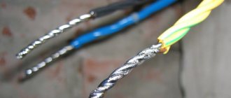
Today, in floor panels, most of these connections are in a deplorable state, since no one is monitoring them. This can be seen in the top two photographs. Often, in addition to the main conductors, they are connected to an intercom, entrance lighting, some kind of socket, signalmen their equipment, etc. Usually they do all this at random and do not pursue the goal of making a reliable connection.
What condition are the “nut” type compressions in your floor panel?
{SOURCE}
What it is
Such products come in a variety of designs and shapes, but in many situations they require nut connectors. The device includes 2 clamping plates made of high-quality anodized steel. Each has special recesses for wires. When it is between the plates, they are tightly compressed by tightening 4 screws.
Branch compression
The terminal blocks are located inside a durable housing, which is made of special plastic. Like the clamp, the housing includes 2 separate parts. The plates are located in the middle: both are attached to the body halves using a spring. Every connection is hidden inside. The “nut” for connecting the cable acts as a connecting and protective device.
Important! The main advantage of the technical component will be the ability to reliably and safely connect copper wires and cables. To carry out such switching, there is no need to cut the main line. It is necessary to clean a small section of the cable placed in the die. The branch is fixed to a perpendicular gutter.
"Nuts" produce various parameters with similar technical indicators. The dimensions of a certain model are selected according to the cross-section of the conductor core. According to GOST, clamps of 4-150 are selected for main lines, and 1.5-120 sq. for branches. mm.
What does a branch squeeze look like?
Installation of networks using sleeves
This option claims to be the most reliable connection method. Any load and quality of wires.
Crimping wires with sleeves
The conductive wires are inserted into a special tube - a sleeve, and crimped with a certain force. There is one thing, but. The cross-section of the wires should not exceed the cross-section of the mounted sleeves. Having inserted and crimped the clip, the sleeve is carefully insulated with heat-shrinkable tubing or other insulating materials.
Overall rating. A great way to securely connect wires. The direction of the conductors can be on different sides of the tube or on one side. The sleeves are quite inexpensive. A good way to reliably connect wires to each other.
There are also disadvantages. Disposable use of sleeves, they are not dismountable. To carry out such work you will need a tool: pressing pliers, which are also used as a special tool. They remove the insulation. They have a crimping device in their arsenal, and electrical installation work takes a little longer.
Connector design
You should start by getting acquainted with the internal structure of the product, studying which will help you understand the principle of the formation of a branch and why it is called that. The fact is that in its shape this connector with steel clips is very similar to a nut (photo below).
This connector consists of the following parts:
- The dielectric outer shell is oval in shape, which is the body of the product with latches located on it.
- A kind of “core”, which is a structure of metal plates held together with bolts.
After disassembling the nut, two dies are visible with recesses (grooves) on each of them, intended for fixing and clamping the bare ends of the wires. Their depth and width depend on the section for which the branch compression sample is designed. The most common models of products of this class and the cross-sections of the cores fixed in them are indicated in the table below.
The samples of “nut” type compressions given in it are used in alternating current networks with operating voltages up to 660 Volts inclusive.
Methods for connecting aluminum and copper wires
There are many situations in which there is an urgent need to organize such connections. And it is not always possible to quickly and easily replace old aluminum wiring in a house with new copper wiring. If, when trying to connect new electrical equipment, it turns out that the wiring in the house is aluminum, then be sure to use one of the available connectors.
We list the main types of electrical connectors for different conductors:
Terminal block (terminal block)
These devices deserve a separate article for consideration, but for now let us draw your attention to the main nuances of their operation. For reliable contact of aluminum and copper conductors in a screw or self-clamping type device, it is necessary to make plates from neutral materials
Alternatively, their surface should be coated with a special paste made exclusively for such actions. This information must be indicated on the label or in the instructions for the product. "Nuts." We wrote about them above. The products got their name due to their structure: the role of the shell is played by a plastic body made of carbolite, the filling is played by clamping plates for good contact. You can use branch clamps without any problems. To begin with, the aluminum conductor line is stripped at the commutation point, after which it is placed in the channel of one of the clamping plates. The copper core of the new equipment is installed in another plate without contact with the external channel. Products with a cross section of 120-150 sq. mm are used mainly by professional electricians, 1.5-4 sq. mm - at home. The piercing clamp is connected directly to the self-supporting insulated wire (SIP) on the main line. It is best to entrust the implementation of such branches to qualified specialists. If you decide to do this yourself, then the device should be connected to the conductors without breaking the insulation (without stripping the cable). Tighten the nut firmly, which will pierce and ensure contact. A homemade connector can be made from one bolt, three brass washers, a nut and electrical tape. To connect aluminum and copper conductors, the area of their direct contact is separated by three washers. This method is considered a temporary connection, but in fact the node will last for several decades.
Connector markings
How to choose a cap? After all, their sizes and twist sections are different and are classified according to the total cross-sectional area of the cores. This area is indicated by the connector number, which can be from one to five. The higher the number, the more wires the cap can connect.
But you need to be careful with such numbers, since there are two types of devices: domestic and European. The designation for both standards is the same - numbers, only European denominations are much smaller than domestic ones
Therefore, when buying PPE, it is better to pay attention to the total cross-section than to its number. All this is written on the packaging
Product marking is carried out as follows: first, the abbreviation PPE is written down, then the type of body is marked (with or without protrusions). The protrusion is necessary for better fixation of the clamp with your fingers. After the housing type, the total cross-section of the wires that are connected in the clamp is written down. The cross section ranges from 0.5 to 10 mm2. As a rule, depending on the type and size of the product, their cases are painted in a certain color to make it convenient to use the caps. The table below indicates the color scheme depending on the type of case, which will make it clearer to you how to choose PPE for twisting:
It should also be remembered that caps can only be used when two identical wires are connected. If you need to connect wires made of aluminum and copper, then it is no longer possible to do this using PPE. In this case, you can use a terminal block, a metal clamp (nut) or a bolt.
Piercing clamps for SIP wire. Characteristics, comparison tables. Connection errors.
The contact in them must be constant and, most importantly, reliable throughout the entire service life of the power line, which is 40 years or more. If somewhere they use homemade hooks for hanging a line and this may not affect its reliability for years, then the connection of SIP wires and cables, SIP and SIP, should only be factory-made.
The two most common types of punctures are waterproof and sealed. All manufacturers have recently opted for sealed ones to modernize and develop their line.
In piercing clamps, contact is ensured by plates with pyramidal teeth and a calibrated breakaway head. The moment of failure varies from 9 to 20 Newton, depending on the brand of “nut” and the cross-section of the connected wires.
Two characteristics must be indicated on the body of each clamp - the cross-section of the main line and the cross-section of the branch. Moreover, these parameters can be in a wide range.
For example, sealed clamp SLIW54 16-120/6-50. The first inscription means a line from 16mm2 to 120mm2 inclusive. The second is the cross-section of the seal cable or SIP, which can be connected through this puncture. When choosing, it is better to buy nuts closest to the larger cross-sections of the wire to be connected in order to ensure better transition contact.
Most of these clamps can be used to connect a cable to a live SIP, since the stripping head and the bolt inside do not come into contact with the contact plate.
All clamps except the breakaway clamp have a second head, but it is only necessary for dismantling. Remember that all these punctures are considered one-time use. Do not confuse them with simple die clamps, which can be unscrewed and tightened at least a hundred times.
There are times when electricians try to reuse piercing clamps on the same or a different line. Although the first head is broken, they use the second one to tighten it.
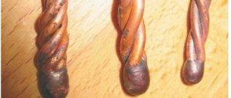
Besides the fact that it is impossible to calculate the exact tightening torque without a torque wrench, for some reason everyone forgets about the deformation of the contact plate teeth after the first puncture. In the photo below, on the right are the teeth after a SIP puncture, on the left - without a puncture. Feel what is called the difference.
Their sharpness is no longer the same, and accordingly, some of them can simply crush the insulation rather than pass through it.
So that manufacturers don’t advertise or talk. Precisely because of the teeth, and not because of the nut breaking.
Technical characteristics and brands of piercing clamps from the most famous manufacturers of SIP fittings:
Combining tires from different materials
Connecting copper and aluminum wires with a walnut clamp
Connecting wires using electric nuts can be done using more than one branch method. Due to the simplicity of the design and the reliability of the resulting connection, these elements are used in any sections of existing electrical networks, including distribution boxes. When using them inside installation products, you need to take into account the dimensions of the clamps themselves and select boxes of appropriate dimensions.
If it is necessary to connect aluminum and copper conductors, electrical wiring clamps “nuts” are simply irreplaceable. The need for them is explained by the following reasons:
- When aluminum and copper wires come into direct contact, the metals in the connection area oxidize over time.
- With prolonged use of the twist, it gradually breaks down and can weaken so much that the circuit through which the load current flows is completely broken.
- As a result of this destruction, the power supply to the object connected to it is completely interrupted.
When forming nut connections, first the copper and aluminum wires are stripped of insulation to the width of the plate. After this, the fasteners are first loosened, and the corresponding wires are inserted into the vacated grooves. At the final stage of assembly, they are tightened with the previously loosened screws. Due to the fact that a brass plate is placed between the copper and aluminum wires in the nut, direct contact between them is not formed.
Branch from a high-voltage line pole
Branch from a high-voltage line pole
According to the provisions of the current regulatory documentation, work on connecting the cable stretched from the power line pole to the entrance to the house is carried out by specialized organizations. This is explained by the fact that the open part of the general electricity supply route is very important from the point of view of the correctness of its arrangement.
Such work can only be performed by specialists who, during installation, use special methods for laying lines, including designing branches from a standard SIP cable.
According to the requirements of the PUE, the following types of wire material can be used with the air connection method:
- Copper conductors with a cross section of 4 mm square at a distance from the pole to the house of about 10 meters;
- the same cable, but with copper conductors with a cross-section of 6 mm square - at distances from 10 to 15 meters;
- aluminum wires with a cross-section of at least 16 mm in diameter - in all cases when, in order to save money, their copper substitute is not used.
Arrangement of a branch from a pole located on the street near the house is exactly the case when an end-to-end connection of the “nut” type is required. When using this connecting element, it will be possible to ensure reliable contact of the conductors of the aluminum cable of the high-voltage line with the copper outlet towards the residential building.
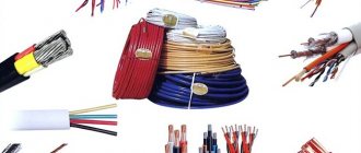
Choosing a cable
Computer networks To build local computer networks and connect Internet access services, a twisted pair cable is used. As the name suggests, the cable consists of several twisted pairs. The conductor in the pair can be made of solid copper wire (Cu) with a thickness of 0.4–0.6 mm or can consist of a large number of stranded copper wires of small diameter (for flexible cables). The best cable is the one whose central core is made of copper. But now there is a budget cable on the market with a copper-coated aluminum (CCA) conductor.
As a rule, the thickness of the conductor is indicated according to the American standard in AWG (American Wire Gauge System). Each AWG value corresponds to a wire diameter expressed in mm and a cross-section expressed in sq. mm. The AWG gauge of a wire reflects its average diameter. The great thing about the AWG standard is that the thicker the wire, the smaller the AWG gauge. This has its own explanation: the AWG value characterizes the number of stages of wire processing, when during manufacturing it is sequentially pulled through gauge holes of smaller and smaller diameters. For example, a 24 AWG cable is thinner than a cable labeled 22 AWG (table).
The standard cable length in a coil is 305 m. This unrounded value resulted from
that the standards were set in the USA, where length is usually measured in feet. If we convert 305 m to US units, we get a round value of 1,000 feet.
Depending on the presence of protection - electrically grounded copper braid or aluminum foil
around twisted pairs - determine the types of cables:
• unshielded twisted pair (UTP - Unshielded twisted pair) – without a protective screen;
• foil twisted pair (FTP - Foiled twisted pair) - there is one common external shield in the form of foil.
Unlike UTP (unprotected twisted pair) cable, FTP cable is not sensitive to low frequency, electromagnetic and high frequency radio interference. Although UTP has traditionally been used, interest in FTP is constantly growing. This is explained by the fact that in networks where 10-Gigabit Ethernet technology will be actively used, shielded cables (FTP) will eliminate not only problems such as inter-cable interference, but also background noise from sources operating in the same frequency range as 10 Gbps systems.
The cable for indoor use has an outer sheath made of PVC. For outdoor use - made of polyethylene, usually black, resistant to UV rays.
The cable may also have a metal cable (most typical for outdoor cable). Cable
with cable is usually used when laying aerial cable routes.
There are several categories of twisted pair cable, which are numbered from Cat. 1 to Cat. 7 and determine
purpose of the cable and its high-speed data transmission capabilities. The most common cable categories are 3 and 5e.
Cat.3 is basically a 2-pair cable. It is used in the construction of telephone and local networks; it supports data transfer rates of up to 10 Mbit/s at a distance of no further than 100 m. The bandwidth is 16 MHz.
Cat.5e, unlike Category 3, is most often a 4-pair cable. It is the most common and is used to build local computer networks. The data transfer speed over this cable is up to 1,000 Mbit/s. Bandwidth – 125 MHz *.
Sometimes you can find 2-pair Category 5e cable. It transmits data at a lower speed - up to 100 Mbit/s, but it also has its advantages: its cost is lower and its thickness is less (the latter makes it easier to install in heavily loaded risers of residential buildings). This cable is used by Internet providers and home local network operators. up to 100 Mbit/s when using 2 pairs.
Telephony
Wires used in telephony (excluding trunk telephone cables), unlike data cables, are not subject to such stringent requirements. To connect a subscriber to public telephone networks, a single-pair cable is often used without any twisting at all (the so-called “noodles”), although in modern conditions the connection is often made with more modern types of cables, including twisted pair category 3. In an apartment, to connect a telephone set to an outlet A multi-core flexible telephone cable with 2 or 4 conductors is used.
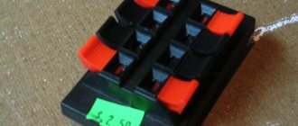
Wiring nut
Terminals are widely used to connect wires and cables. To make the connection, you must remove the insulation and insert the stripped wire into the terminal. But it is not at all necessary to limit yourself to stripping the ends of the conductors. Insulation can be removed anywhere. In this case, you don’t have to cut the wire, but use a terminal of a special design - a clamp. This device can connect two wires without cutting them at the junction. But most often it is used to obtain branches from the main wire, which in this case is similar to an electrical bus.
The main part of this product, which is also called “walnut” by electricians, consists of several steel plates. Usually there are three:
- The top and bottom are equipped with a groove.
- The middle plate is flat.
The grooves are mutually perpendicular and are designed to enclose a core of suitable diameter.
The dimensions of the grooves determine one or another “nut” model, which is recommended to be used for connecting conductors with certain cross-sections. The image below shows that the wires in this connection do not touch. Therefore, in the “nut” it is possible to connect an aluminum wire with a copper one. The metal part is placed in a plastic case. In some models it is sealed.
A compression connector called a "die"
One of the compression models with the body disassembled
Nut, terminal block, soldering, twisting - how to properly connect electrical wires
Connecting cables and wires
The quality of the electrical contact is determined by the quality and reliability of the wire connection, without which not a single installation operation can still be done.
In places where electrical contacts are directly connected, the following must be provided:
reliability of the contact - its connection resistance should not exceed the resistance of a solid section of wire;
mechanical resistance to stretching - if accidental stretching is possible at the junction, then the strength of the connection should not be less than the strength of a solid section of wire;
The most common wire connection options:
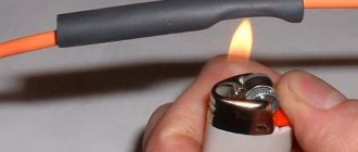
#1 - twist
This is the simplest and, obviously, the most common connection method. To connect two wires by twisting, you simply need to clear their ends of insulation (it is highly advisable to remove at least 5 cm of the insulating coating from each) and twist both bare wires together.
Next, such twisting is insulated with ordinary electrical tape or a special cap, which is screwed onto the twisted wires, properly insulating their bare parts and compressing the contact
It is important to remember that wires made of dissimilar metals (aluminum and copper, for example) are strictly prohibited from being connected by twisting.
#2 - soldering
This method, as a rule, requires more time, but is more reliable than twisting. The fact is that in the place of twisting, even of very high quality, resistance and varying degrees of overheating of the twisted contacts are inevitable, which leads to damage to the insulation and can cause a short circuit and fire.
Soldering provides a more reliable electrical contact with low resistance and sufficient strength. Soldering of wires is most often carried out using conventional tin-lead solder and rosin.
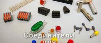
#3 - terminal block
This is the name given to special insulating plates with contacts. These plates are divided into two types according to the method of fastening the wires: a terminal block with a pressing plate and a terminal block with tightening screws.
The latter has one significant drawback: when tightening, the wire (especially if it is aluminum or stranded) in such a terminal block is often damaged by the screw. Therefore, a terminal block with a pressure plate is considered more reliable. We also note that terminal blocks of both types are also used for connecting wires made of dissimilar metals.
#4 - spring terminal
Currently, this connection method is rightfully considered the most effective and fastest. At one end, the conductive core only needs to be cleared of insulation and inserted into the terminal, after which the wire is secured with a spring lock.
Spring terminals are also versatile and are used to connect solid wires of various cross-sections, soft stranded wires and wires made of dissimilar metals (for example, to connect a copper cable to an aluminum overhead line cable).
#5 - nut (branch squeeze)
... used to connect to main lines without breaking them and consists of metal plates with screws in an insulating box housing. “Nuts” are also often used to connect wires made of dissimilar metals and, in particular, to connect a copper cable to an aluminum overhead line cable.
Well, to finish the post, let us remind you how at home you should connect the same wires from dissimilar metals, that is, a copper wire and an aluminum wire.
If it turns out that the terminal clamp is not available, then we will do without it. However, twisting in this case, as they say, is also not an option due to its disadvantages listed above. Instead, it is better to use a regular bolt with a nut and washer, that is, in fact, a terminal block, but from scrap materials. The disadvantage of such a connection is that it is clumsy, so for high-quality insulation of the tape you will also need a little more.
What is the best way to connect wires in a junction box?
Above are all the permitted methods by which you can connect electrical wires in a junction box when installing wiring in an apartment or house. Each of them has its own characteristics, strengths and weaknesses. Obviously, the choice should be made between two:
1. Welding of wires should definitely be considered first, because... This method of connecting wires guarantees maximum reliability of all wiring. If you want to be completely confident in your electrical network, and as you know, connections are the bottlenecks of any electrical wiring, I recommend renting, buying or assembling a welding machine yourself in order to be able to weld wires in boxes.
2. Connecting wires with self-clamping terminals, suitable for those who want to do the wiring quickly, while still getting a fairly high-quality connection
In this case, it is very important to correctly calculate the electrical wiring and not overload it. Many electricians, not just self-taught ones, have recently chosen terminals because of the ease and speed of installation
I would recommend performing crimping only in cases where you already have specialized equipment (press jaws) and material - sleeves.
And if you know other convenient permitted ways to connect wires during electrical installation, leave a comment. In addition, write about your experience, which connection method and why you prefer. I think this will be useful to everyone! Just as usual, any comments on the topic, questions, discussions are welcome!
Application example and assembly procedure
As an example of the use of nut-type products, a three-phase cable is usually considered, from which wiring with a cross-section of 1.5 mm2 is removed. The correct approach to arranging such a branch involves the following procedure:
- On a cable line with a cross-section of 6 mm2, at the outlet point, the insulation is removed for the length of the connector pressure plate.
- The nut itself is prepared by taking a screwdriver and using it to first pry up and then remove the locking ring on the body.
- The halves of the product are separated.
- You need to unscrew the clamping bolts from the contact plates.
- The protective insulation is also removed from the outlet core with a smaller cross-section to a length corresponding to the size of the pressure plate.
At the final stage of the work, the exposed parts are first tucked into the grooves for the connector dies, and then tightly tightened with screws.
When tightening the screws, do not apply too much force, which could damage the clamp threads. Upon completion of this operation, proceed to assembling the nut body
It is important to distinguish between the two halves, which have four target holes. One of them is simply soldered, the other is intended for outputting the outgoing wire, and two more are for wiring the main cable
Parts of the assembled body are securely fixed with special locking rings.
Purpose and advantages of connectors
Marking of cable clamps
The nut clamp for electrical wires is especially in demand in situations where it is necessary to prepare a branch from the main wire without the need to cut it. An illustrative example of the use of this connector is its use in floor access panels, from which electricity is supplied to apartments via branches from the main cable line. When registering the next branch to a residential premises, the main wire at each site is laid in an unbreakable manner. Power is supplied to individual apartments by installing a branch using electrical wiring nuts.
With such an organization, a loss of contact on the second floor of a building, for example, will lead to a simultaneous loss of power in all apartments located on its upper floors.
Wire nuts can be installed in power supply lines with an operating voltage of up to 660 Volts, within which it is possible to obtain a reliable connection of the outgoing wire to the main cable route. Thanks to the use of these electrical elements, significantly less time is spent on the corresponding installation work. At the same time, special skills and efforts are not required from the installer.
Nuts for connecting wires do not guarantee absolute tightness, since under certain conditions dust or moisture may enter them. To avoid this trouble, experts advise wrapping the “nut” compression housing with insulating tape after forming the connection.
The indisputable advantages of clamps of this type include:
- With their help, it is possible to connect branches without breaking the cable.
- To work with these connecting elements, no special training or high qualifications are required.
- By using nuts to connect electrical wires, it is possible to combine dissimilar materials (copper and aluminum, in particular).
The last advantage is especially important when installing conductive lines, since in this case oxidation of contacts and the possibility of a complete interruption in the supply of electricity to the consumer are eliminated
Compression models
To branch from the main cable lines, it is necessary to use high-quality clamps. When choosing, you need to familiarize yourself with the main characteristics of the models.
Branch compressor U-733 m16-35/o1.5-10
Products from the French manufacturer Schneider Electric. The product is mounted externally. Made from aluminum and copper. The device does not have a protective coating, the connection is screw. Temperature indicators for use vary in the range of −25+60 degrees, settings −5C +60. The price is approximately 40 rubles*
You might be interested in Features of pliers and pliers
Pros:
- build quality;
- made of aluminum and copper;
- wide operating temperature range.
Minuses:
There is no protective surface coating.
Branch compressor U-733 m16-35/o1.5-10
Branch compressor U-731 m4-10/o1.5-10
Designed for making branches from cables and wires with voltages up to 660 V. The insulation is first removed at the installation site without cutting the conductor. The warranty period is 10 years. The body is made of polycarbonate and is flame resistant. The contact material is anodized steel. The cost is approximately 70 rubles.
Pros:
- build quality;
- made of polycarbonate and quality steel;
- long period of use.
Minuses:
The housing has a leak-proof design.
Branch compressor U-731 m4-10/o1.5-10
Branch compressor U-734 m16-35/o16-25
Product from the developer Hegel. Manufacturing materials: polypropylene and steel. The fire resistance of the housing is 650 degrees. The color of the clamp is black, the number of contacts is 2. Installation occurs by screwing the bolts and snapping the housing onto the unit. It is used primarily for branches of cables and wires. The price is approximately 35 rubles.
Pros:
- made of polypropylene and steel;
- fire resistance;
- ease of installation.
Minuses:
The housing has a leak-proof design.
Branch compressor U-734 m16-35/o16-25
Soldering or welding wires
This method is reliable. Typically, this method of connection in a junction box involves first stripping and twisting the ends, after which they are dipped into heated solder. It is advisable to connect aluminum to aluminum wires by soldering. They are then insulated using a heat pipe or insulating tape.
Method of twisting wires
It is strictly not recommended to immediately cool soldered wires in water; microcracks that occur with this type of cooling affect the quality of the connection. They don't last long.
Evaluation of the soldering method. It provides strong circuit contacts and excellent quality, is not expensive, and is the most reliable method of connecting electrical wires in a soldered box.
Technological disadvantage. You can't do this without a soldering iron. The speed of work is not high. The connection is naturally not detachable. It follows from this that soldering is done in extreme cases, using more modern connection methods. It has not been popular among masters for a long time because it takes more time.
There is also a less common method for connecting electrical wires, welding. The process is similar, but requires the use of a special welding machine, of course, and certain skills.
Using a bolt
Bolted connection is one of the simplest and most effective. In order to connect any wires, you only need a bolt, a few washers and a nut. The insulating layer is peeled off the conductor. A washer is put on the bolt, and a coil of wire is placed on top of it around the bolt.
The next washer is put on and the second wire is wrapped around the bolt leg. The last washer is put on and secured tightly with a nut. The structure is insulated in the traditional way - with insulating tape.
The disadvantage of this method is the bulkiness of the structure, which will not allow you to hide the wires in the junction box.
A simple connection of two wires to a bolt requires subsequent insulation.
Rules for connecting wires
To connect the desired conductor to the main electrical cable, you must first disassemble the clamp. To do this, you need to remove the retaining rings located on the sides of the “nut”. After this, the bolts connecting the dies and the plate between them are unscrewed.
Then it is necessary to remove the insulation from the cable in accordance with the length of the intermediate plate inside the clamp. It is no longer advisable to strip the insulation.
How to connect the wires further? Very simple! The exposed sections of the conductors are inserted into the grooves of the dies, and then tightened with screws. Now the resulting structure is placed back into the insulated polycarbonate body of the “nut”. You will notice that there are four holes in the case. The first hole is tightly sealed, the second is intended for a branch cable, and the main electrical conductor is pulled through the remaining two holes. This is how electrical cables are connected using a nut.
Do not forget that a “walnut” type connection is not able to guarantee the tightness of all joints, therefore, during operation under different climatic and weather conditions, dust, dirt and moisture can get inside the case. To provide some degree of protection, the compression housing must be insulated or, in other words, simply wrapped with electrical tape.
Finally, we recommend watching a video that clearly shows how to connect wires using a nut clamp:
Device
The design of the electrical installation element includes a dielectric housing, which is made of special plastic. The material is classified as thermoplastics, which are polyesters. A metal core is installed in the compression housing, which includes 2 dies with a plate in the middle. Both parts are connected to the others via screws. Grooves are made in 2 dies to lay the wire. The nut terminals are marked approximately the same.
Compression design