Simple overlapping or slight twisting of the contact surfaces of the connected conductors does not provide good contact, since due to micro-irregularities, actual contact does not occur over the entire surface of the conductors, but only at a few points, which leads to a significant increase in the contact resistance.
At the point of contact of two conductors, a transition resistance of the electrical contact always arises, the value of which depends on the physical properties of the contacting materials, their condition, the compression force at the point of contact, temperature and the actual area of contact.
From the point of view of the reliability of electrical contact, aluminum wire cannot compete with copper . After a few seconds of exposure to air, the pre-cleaned aluminum surface is covered with a thin, hard and refractory oxide film with high electrical resistance, which leads to increased transient resistance and strong heating of the contact zone, resulting in an even greater increase in electrical resistance. Another feature of aluminum is its low yield strength. A tightly tightened connection of aluminum wires weakens over time, which leads to a decrease in the reliability of the contact. In addition, aluminum has poorer conductivity. That is why the use of aluminum wires in household electrical systems is not only inconvenient, but also dangerous.
Copper oxidizes in air at normal residential temperatures (about 20 °C). The resulting oxide film does not have great strength and is easily destroyed when compressed. Particularly intense oxidation of copper begins at temperatures above 70 °C. The oxide film on the copper surface itself has insignificant resistance and has little effect on the value of the contact resistance.
The condition of the contact surfaces has a decisive influence on the growth of the contact resistance. To obtain a stable and durable contact connection, high-quality cleaning and surface treatment of the connected conductors must be performed. The insulation from the conductors is removed to the required length with a specialized tool or knife. Then the exposed parts of the veins are cleaned with emery cloth and treated with acetone or white spirit. The length of the cutting depends on the characteristics of the specific method of connection, branching or termination.
The transient contact resistance decreases significantly with increasing compression force of the two conductors, since the actual contact area depends on it. Thus, to reduce the transition resistance in the connection of two conductors, it is necessary to ensure sufficient compression, but without destructive plastic deformations.
There are several ways to make an electrical connection. The highest quality of them will always be the one that provides, under specific conditions, the lowest value of transient contact resistance for the longest possible time.
According to the “Rules for Electrical Installations” (clause 2.1.21), connection, branching and terminating of wires and cables must be done by welding, soldering, crimping or clamping (screw, bolt, etc.) in accordance with current instructions. In such connections it is always possible to achieve a consistently low transient contact resistance. In this case, it is necessary to connect the wires in compliance with technology and using appropriate materials and tools.
Connecting wires in a junction box is an important and responsible operation. It can be performed in various ways: using terminal blocks, soldering and welding, crimping, and often ordinary twisting. All of these methods have certain advantages and disadvantages. It is necessary to select a connection method before starting installation, as this also involves the selection of appropriate materials, tools and equipment.
When connecting wires , the neutral, phase and ground wires must be of the same color. Typically, the phase wire is brown or red, the neutral wire is blue, and the protective ground wire is yellow-green.
Very often, electricians have to connect a wire to an existing line. In other words, it is necessary to create a branch of wires. Such connections are made using special branch clamps, terminal blocks and piercing clamps.
When copper and aluminum wires are directly connected, copper and aluminum form a galvanic couple, and an electrochemical process occurs at the point of contact, as a result of which the aluminum is destroyed. Therefore, to connect copper and aluminum wires, you need to use special terminal or bolt connections.
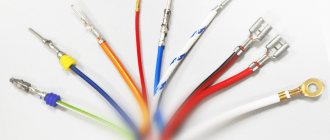
Wires connected to various devices often require special ferrules that help ensure reliable contact and reduce contact resistance. Such lugs can be attached to the wire by soldering or crimping.
Tips come in a wide variety of types. For example, for copper stranded conductors, lugs are produced from a solid-drawn copper pipe, flattened and drilled for a bolt on one side.
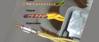
Welding. Connecting wires by welding.
Connecting conductors by welding provides a monolithic and reliable contact, so it is widely used in electrical installation work.
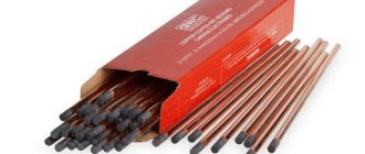
Welding is performed at the ends of pre-stripped and twisted conductors with a carbon electrode using welding machines with a power of about 500 W (for twist cross-sections up to 25 mm2). The current on the welding machine is set from 60 to 120 A depending on the cross-section and number of wires being welded.
Due to the relatively low currents and low (compared to steel) melting point, the process occurs without a large dazzling arc, without deep heating and spattering of the metal, which makes it possible to use safety glasses instead of a mask. At the same time, other security measures may be simplified. After welding is completed and the wire has cooled, the bare end is insulated using electrical tape or heat-shrink tubing. After a little training using welding, you can quickly and efficiently connect electrical wires and cables in the power supply system.
When welding, the electrode is brought to the wire being welded until it touches, then withdrawn a short distance (OD—1 mm). The resulting welding arc melts the twisted wires until a characteristic ball is formed. Touching the electrode should be short-term to create the desired melting zone without damaging the wire insulation. It is impossible to make a longer arc length, since the welding site turns out to be porous due to oxidation in the air.
Currently, it is convenient to carry out welding work on connecting electrical wires with an inverter welding machine, since it has a small volume and weight, which allows the electrician to work on a stepladder, for example, under the ceiling, hanging the inverter welding machine on his shoulder. To weld electrical wires, a graphite electrode coated with copper is used.
In a welded joint, electric current flows through a monolithic metal of the same type. Of course, the resistance of such connections turns out to be record low. In addition, this connection has excellent mechanical strength.
Of all the known methods of connecting wires, none of them can be compared with welding in terms of durability and contact conductivity. Even soldering breaks down over time, since the connection contains a third, more fusible and loose metal (solder), and at the border of different materials there is always additional contact resistance and destructive chemical reactions are possible.
Advantages over a soldering iron
Copper is a specific metal that must be welded in a well-protected area to prevent the interaction of ambient air and carbon. However, when welding wires made of this metal, there is no need to create a long weld seam. Therefore, the process of welding electrical wiring can be performed outdoors.
To solder two copper wires to each other, you need to simply melt the ends of the temporary twisting point in a short period of time. An ordinary inverter or welding transformer is perfect for these purposes. However, it should be noted that the equipment used must produce a current strength that is sufficient to fuse the edges of the cables.
The main advantage of using an inverter and transformers compared to a soldering iron is that:
- there is no need to additionally use filler material during welding;
- there is no need for tinning the metal;
- weld metals much faster than soldering (effective when performing large volumes of wiring installation work);
- welding machines, by changing the operating mode, can be switched to work with conductors of any cross-section (to solder materials with different diameters, you need to purchase soldering irons that differ in power).
In addition, when laying electrical wiring, cables of large thickness can be used. In this case, it will not be possible to connect them together using a soldering iron. Also, during soldering, when using a soldering iron, you must constantly monitor its temperature. After all, if you use a poorly heated or low-power soldering iron, the wiring connections will not warm up well.
Soldering. Connecting wires by soldering.
Soldering is a method of joining metals using another, more fusible metal. Compared to welding, soldering is simpler and more affordable. It does not require expensive equipment, is less fire hazardous, and the skills needed to perform good quality soldering will require more modest skills than when making a welded joint. It should be noted that the metal surface in air is usually quickly covered with an oxide film, so it must be cleaned before soldering. But the cleaned surface can quickly oxidize again. To avoid this, chemicals are applied to the treated areas - fluxes, which increase the fluidity of the molten solder. This makes the soldering stronger.
Soldering is also the best way to terminate copper strands into a ring - the soldered ring is evenly coated with solder. In this case, all wires must completely fit into the monolithic part of the ring, and its diameter must correspond to the diameter of the screw clamp.
The process of soldering wires and cable cores consists of covering the heated ends of the connected wires with molten tin-lead solder, which after hardening provides mechanical strength and high electrical conductivity of the permanent connection. The soldering must be smooth, without pores, dirt, sagging, sharp bulges of solder, or foreign inclusions.
To solder copper conductors of small cross-sections, use solder tubes filled with rosin, or a solution of rosin in alcohol, which is applied to the joint before soldering.
To create a high-quality soldered contact connection, the wire (cable) cores must be thoroughly tinned, and then twisted and crimped. The quality of the soldered contact largely depends on correct twisting.
After soldering, the contact connection is protected by several layers of insulating tape or heat shrink tubing. Instead of insulating tape, the soldered contact connection can be protected with an insulating cap (PPE). Before this, it is advisable to coat the finished joint with a moisture-resistant varnish.
Heating of parts and solder is carried out with a special tool called a soldering iron. A prerequisite for creating a reliable connection using soldering is the same temperature of the surfaces being soldered. The ratio of the temperature of the soldering iron tip and the melting temperature is of great importance for the quality of soldering. Naturally, this can only be achieved with the help of a properly selected tool.
Soldering irons vary in design and power. To perform household electrical work, a conventional electric rod soldering iron with a power of 20-40 W is quite sufficient. It is advisable that it be equipped with a temperature regulator (with a temperature sensor) or at least a power regulator.
Experienced electricians often use an original method for soldering. In the working rod of a powerful soldering iron (at least 100 W), a hole with a diameter of 6-7 mm and a depth of 25-30 mm is drilled and filled with solder. In a heated state, such a soldering iron is a small tin bath, which allows you to quickly and efficiently solder several multi-core connections. Before soldering, a small amount of rosin is thrown into the bath, which prevents the appearance of an oxide film on the surface of the conductor. The further soldering process involves lowering the twisted connection into such an improvised bath.
Soldering as a reliable alternative to twisting
The closest alternative to twisting, which is prohibited for electrical installation, is to connect wires using the soldering method. It requires special tools and consumables, but provides absolute electrical contact.
Advice! Overlapping wire soldering is considered the most unreliable in technology. During operation, the solder crumbles and the connection opens. Therefore, before soldering, apply a bandage, wrap a piece of wire of a smaller diameter around the parts being connected, or twist the conductors together.
You will need an electric soldering iron with a power of 60–100 W, a stand and tweezers (pliers). The soldering iron tip should be cleaned of scale, sharpened, having first selected the most suitable shape of the tip in the form of a spatula, and the body of the device should be connected to the ground wire. Among the “consumables” you will need POS-40, POS-60 solder from tin and lead, rosin as a flux. You can use solder wire with rosin placed inside the structure.
If you need to solder steel, brass or aluminum, you will need a special soldering acid.
Important! Do not overheat the junction points. To prevent the insulation from melting when soldering, be sure to use a heat sink. To do this, hold the bare wire between the heating point and the insulation with tweezers or needle-nose pliers.
- The wires stripped of insulation should be tinned, for which the tips heated with a soldering iron are placed in a piece of rosin; they should be covered with a brown-transparent layer of flux.
- We place the tip of the soldering iron tip into the solder, grab a drop of molten solder and evenly process the wires one by one, turning and moving along the tip blade.
- Attach or twist the wires together, securing them motionless. Warm up with the tip for 2–5 s. Treat the areas to be soldered with a layer of solder, allowing the drop to spread over the surfaces. Turn over the wires to be connected and repeat the operation on the reverse side.
- After cooling, the soldering joints are insulated in the same way as twisting. In some compounds, they are pre-treated with a brush dipped in alcohol and coated with varnish.
Advice! During and after soldering for 5–8 s. The wires cannot be pulled or moved, they must be in a stationary position. A signal that the structure has hardened is when the solder surface acquires a matte tint (it shines in the molten state).
Connecting wires with screw terminals
One common way to create a contact is to use screw terminal blocks . In them, reliable contact is ensured by tightening the screw or bolt. In this case, it is recommended to connect no more than two conductors to each screw or bolt. When using stranded wires in such connections, the ends of the wires require preliminary tinning or the use of special tips. The advantage of such connections is their reliability and disassembly.
According to their purpose, terminal blocks can be feed-through or connecting.
Connecting screw terminal blocks are designed to connect wires to each other. They are usually used for switching wires in junction boxes and distribution boards.
Feed-through terminal blocks are used , as a rule, for connecting various devices (chandeliers, lamps, etc.) to the network, as well as for splicing wires.
When connecting wires with stranded conductors using screw terminal blocks, their ends require preliminary soldering or crimping with special lugs.
When working with aluminum wires, the use of screw terminal blocks is not recommended, since aluminum cores, when tightened with screws, are prone to plastic deformation, which leads to a decrease in the reliability of the connection.
Spring and screw terminals
The above is quite easy to practice in everyday work with household networks. Since the abandonment of stranded conductors has become almost universally accepted, either solid conductors or strands processed by soldering or sleeve tips can be connected. One of the oldest and most reliable methods is screw blocks, which cut deeply into the core and provide good contact at the expense of the dynamic strength of the core. For permanent connections, it is also recommended to fill the open parts of the pads and the “necks” of the screws with hot glue.
An alternative to such connections are WAGO spring clamps and the like. The core in such a clamp can be bent several dozen times, and it will not break off at a weak point. For use in damp environments, it is recommended to purchase spring pads filled with petroleum jelly. Such devices, despite a slight increase in the total cost of the project, remain detachable for quickly changing the network configuration when an error is detected, at the same time, their service life is comparable to a cable - from 50 years.
Wago quick release coupling
Connecting wires with self-clamping terminal blocks
Recently, self-clamping terminal blocks of the WAGO type . They are designed for connecting wires with a cross-section of up to 2.5 mm2 and are designed for an operating current of up to 24 A, which allows you to connect a load of up to 5 kW to the wires connected by them. In such terminal blocks you can connect up to eight wires, which significantly speeds up the installation of wiring in general. True, compared to twisting, they take up more space in soldered boxes, which is not always convenient.
The screwless terminal block is fundamentally different in that its installation does not require any tools or skills. The wire, stripped to a certain length, is inserted into place with little effort and securely pressed by a spring. The design of a screwless terminal connection was developed by the German company WAGO back in 1951. There are other manufacturers of this type of electrical products.
In spring-loaded self-clamping terminal blocks, as a rule, the effective contacting surface area is too small. At high currents, this leads to heating and release of the springs, resulting in a loss of their elasticity. Therefore, such devices should be used only on connections that are not subject to heavy loads.
WAGO produces terminal blocks both for installation on a DIN rail and for fastening with screws to a flat surface, but when installed as part of home electrical wiring, construction terminal blocks are used. These terminal blocks are available in three types: for distribution boxes, for lamp fittings and universal.
WAGO terminal blocks for distribution boxes allow you to connect from one to eight conductors with a cross-section of 1.0-2.5 mm2 or three conductors with a cross-section of 2.5-4.0 mm2. And terminal blocks for lamps connect 2-3 conductors with a cross section of 0.5-2.5 mm2.
The technology for connecting wires using self-clamping terminal blocks is very simple and does not require special tools or special skills.
There are also terminal blocks in which the conductor is fixed using a lever. Such devices allow you to achieve good pressure, reliable contact and are easy to disassemble.
What is the most reliable way to connect electrical wires?
Every electrician who performs electrical installation work knows that the most critical area during electrical installation is connecting the wires. The main requirement for them is to create maximum conductivity between the wires and reliability of the joint. Ideally, the connection resistance should be minimal and not increase during long-term operation. Failure to comply with this requirement leads to overheating of the wire connections, damage and often a fire.
Currently, many ways of connecting conductors have been invented, each of them has its own advantages and disadvantages. Here are the most popular: twisting, welding, soldering, terminal connections and clamps, screw branch clamps, bolt connectors, PPE insulating connecting clamps, WAGO type clamps, crimping. Let's look at them.
Twist
Once the most popular method of connecting wires among electricians, it is now prohibited. In the 1970s, wires with a cross-section of up to 10 mm2 inclusive were allowed to be connected by twisting, without soldering or welding. But in the 7th edition of the “Rules for Electrical Installations”, published in 2009, in paragraph 2.1.21 of Chapter 2, it is written: “Connection, branching and terminating of wires and cables must be carried out using crimping, welding, soldering or clamps (screw, bolted, etc.) in accordance with current instructions approved in the prescribed manner."
As you can see, there is no twist in the list. Here it should be clarified that twisting is prohibited in its pure form, i.e. as a complete technological process, but with other connection methods, for example when welding or soldering wires, it is permitted and used as its component.
The prohibition of twisting is due to the fact that the quality of contact, i.e. its conductivity deteriorates over time. In a fresh twist, the contact resistance (TS) may be normal, which is why some electricians advocate it so much. Note that the twist strength depends on the contact area of the wires, the force of their compression, the cleanliness of their surface (lack of dirt) and the presence of an oxide film.
Over time, the wires, interacting with oxygen in the air, oxidize, the PS at the points of their connection increases, and the twist heats up, heating leads to an even greater increase in the oxidation of the wires and a weakening of the compression force of the wires, which makes the twist heat up even more.
The higher the current in the circuit, the more the twist heats up. It is important to note here that the circuit breakers will not break the electrical circuit in which the twist has heated up to the point of fire, since the current in the circuit remains almost unchanged, and only the temperature of the joint increases. This is precisely the danger of twisting, and this is the main cause of electrical fires, so twisting is prohibited.
Welding
According to the unanimous opinion of electricians, welding is the most reliable type of connecting wires. The PS at the junction of welded wires does not increase over time, so the welded wires do not overheat and last for many decades, providing the proper level of fire safety.
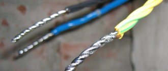
The technology (sequence) for welding wires is shown in Fig. 1, and photographs of welded copper and aluminum wires are shown in Fig. 2 and Fig. 3, respectively. Welding of wires is usually carried out with alternating current (Fig. 1, c) and lasts 2.3 s. As a welding electrode, you can use copper-plated graphite electrodes, sold in specialized welding equipment stores, or graphite brushes from commutator motors, or brushes from trolleybus rods.
Both factory-made clamps (Fig. 4a) and home-made clamps can be used as electrode holders. Alligator clips are also suitable, the same ones that are used to connect to lead acid car batteries. Wires connecting the welding machine to the network
220 V/50 Hz, can be of any required length, with a cross-section of 2.5 mm2, and the wires between the welding machine and the twist must be up to 1.5 m long with a cross-section of 10 mm2, in extreme cases -6.0 mm2, but in this case, no more than 1.0 m long. These wires will carry a current of up to 100 A.
The magnitude of the current depends on the number of wires in the twist being welded and, naturally, on the power of the welding transformer. If the welding machine is capable of delivering a current of 50.90 A, then this is enough for practical work.
As a contact of a welding machine with twisting, i.e. “mass”, use pliers, the handle of which is connected with a wire through a bolt and terminal (Fig. 4,b) to the welding machine. Pliers, in addition to creating contact between the twist and the welding machine, act as a heat sink that prevents the wire insulation from burning.
Copper wires are easy to weld. If you have not made twists before, then you need to practice on separate pieces of wire with different numbers in the twist. Aluminum wires are difficult to weld; the main obstacle here is aluminum oxide, its melting point is 2050°C, although pure aluminum melts at 660°C. In addition, aluminum oxide does not respond well to flux.
A good solvent for it is the following composition (sold in specialized stores for welding): - potassium fluoride - 1 part; - zinc chloride - 8 parts; — lithium chloride — 32 parts; - potassium chloride - 5 parts. Before use, this flux must be diluted to a thick paste, rubbed onto aluminum wires and then welded in the same way as copper wires.
Connecting wires with connecting insulating clamps
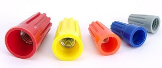
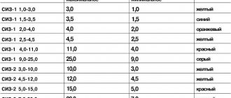
One of the popular connecting products among electrical installers is the connecting insulating clamp (PIC) . This clamp is a plastic case, inside of which there is an anodized conical spring. To connect the wires, they are stripped to a length of about 10-15 mm and folded into a common bundle. Then the PPE is screwed onto it, rotating clockwise until it stops. In this case, the spring compresses the wires, creating the necessary contact. Of course, all this happens only when the PPE cap is selected correctly according to its rating. Using such a clamp, it is possible to connect several single wires with a total area of 2.5-20 mm2. Naturally, the caps in these cases are of different sizes.
Depending on the size, PPE has specific numbers and is selected according to the total cross-sectional area of the strands being twisted, which is always indicated on the packaging. When choosing PPE caps, you should focus not only on their number, but also on the total cross-section of wires for which they are designed. The color of the product has no practical meaning, but can be used to mark phase and neutral conductors and ground wires.
PPE clamps significantly speed up installation, and due to the insulated housing, they do not require additional insulation. True, their connection quality is somewhat lower than that of screw terminal blocks. Therefore, other things being equal, preference should still be given to the latter.
[Your opinion] Crimping or soldering? Who can resist nature?
Welcome to ChipTuner Forum.
Theme Options
Region 36
santa62
There is nothing to squeeze with. There are no ticks. But hitting with a hammer is not pretty. About soldering they say it cracks at the soldering itself and the wire becomes brittle after soldering. And it will also sway at least a little in the wind.
Added after 1 minute
Region 36
Region 36
viktor5462
s a n i
Maslov Vladimir
Region 36
Somehow I don’t understand you! There should be a bus running from the circuit to the switchboard (I don’t remember the dimensions). And there is a welded bolt, and from it there is an entry into the shield. IMHO, take this VERY CAREFULLY. Everything else is from the evil one. Only a loop of cable, clamped under the washer, washer, and nut.
Added after 34 minutes
And hey, I’m thinking about making a second circuit. And parallelize it.
Taras
sergcr
santa62
Just as it heats up to 185 Celsius, it will work like a fuse (if you want to solder it at the joint). So at least the car won't burn out!
Added after 7 minutes
Certainly. If you use “rosin”, “soldering acid”, etc. fluxes from the 20th century.
Hummer-74
Taras
I have nothing against soldering; you can solder it if you don’t have a press. When soldering, use neutral fluxes or rosin, and nothing will crack or rot. But we need to be friends with the RES members, they have a lot of good things that we need, including the press. And they are not bad guys. Ask them for a press and squeeze it. Or buy a crimping service from them.
I don’t understand what’s wrong with these materials, other than a cold soldering iron? Well, I have nothing against rosin and Soviet POS-61 (I haven’t tried POS-60, but I don’t see any difference). If everything is clean and heated to the required temperature, then the solder flows into the soldering area like a teardrop, and the quality is excellent, just a sight for sore eyes.
kimmaster
Somehow I don’t understand you! There should be a bus running from the circuit to the switchboard (I don’t remember the dimensions). And there is a welded bolt, and from it there is an entry into the shield. IMHO, take this VERY CAREFULLY. Everything else is from the evil one. Only a loop of cable, clamped under the washer, washer, and nut.
Added after 34 minutes
And hey, I’m thinking about making a second circuit. And parallelize it.
That's just where the tire goes, and there's a bolt on it. And the wire will be between the bolt and the shield. I will do it again as I will pull it into the garage. Right now I have a counter with a box on my facade, then there is a shield going along the wall to the back wall of the house. From the panel there is 1 phase to the house and 3 phases to the garage. How to get into the garage, I’ll draw another circuit from behind the garage. And the main circuit is where the meter is located right now.
Added after 5 minutes
I have nothing against soldering; you can solder it if you don’t have a press. When soldering, use neutral fluxes or rosin, and nothing will crack or rot. But we need to be friends with the RES members, they have a lot of good things that we need, including the press. And they are not bad guys. Ask them for a press and squeeze it. Or buy a crimping service from them.
I don’t understand what’s wrong with these materials, other than a cold soldering iron? Well, I have nothing against rosin and Soviet POS-61 (I haven’t tried POS-60, but I don’t see any difference). If everything is clean and heated to the required temperature, then the solder flows into the soldering area like a teardrop, and the quality is excellent, just a sight for sore eyes.
The wire dangles from the meter to the circuit. It's about a meter long. I'm thinking of going to the store to look at the staples to secure.
Source
Twisting. Twisted connection of wires.
Twisting of bare wires as a connection method is not included in the Electrical Installation Rules (PUE). But despite this, many experienced electricians consider a correctly performed twist as a completely reliable and high-quality connection, arguing that the transition resistance in it is practically no different from the resistance in the whole conductor. Be that as it may, good twisting can be considered one of the stages of connecting wires by soldering, welding or PPE caps. Therefore, high-quality twisting is the key to the reliability of all electrical wiring.
If the wires are connected according to the “as it happens” principle, a large transition resistance may arise at the point of their contact with all the negative consequences.
Depending on the type of connection, twisting can be performed in several ways, which, with a small transition resistance, can provide a completely reliable connection.
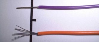
First, the insulation is carefully removed without damaging the wire core. Sections of cores exposed to a length of at least 3-4 cm are treated with acetone or white spirit, sanded with sandpaper to a metallic shine and tightly twisted with pliers.
Testing the connection resistance
The test was carried out using a Micromilliohmmeter IKS-1A device. It is designed to determine the electrical resistance of bolted and terminal connectors.
For each connector, pieces of wire with a cross section of 2.5 mm 2 and a length of 3.5 cm each were taken. After this, the device was connected to the two ends of the conductor and a current of 1.2 A was passed through it. Here are the readings:
In the tests, the screw terminal block performed best. The twist, oddly enough, surpassed Wago and KBM. However, the resistance reading alone is not enough to decide which type of connection is best for wiring. After all, a lot depends on the contact area, and over time, the joint can become clogged with dust and dirt, which will worsen the contact. Let's take a closer look at each type separately.
Connecting wires by crimping
The crimping method is widely used to make reliable connections in junction boxes. In this case, the ends of the wires are stripped, combined into appropriate bundles and pressed. The connection after crimping is protected with electrical tape or heat shrink tubing. It is one-piece and does not require maintenance.
Crimping is considered one of the most reliable methods of connecting wires. Such connections are made using sleeves by continuous compression or local pressing with special tools (press jaws), into which replaceable dies and punches are inserted. In this case, the wall of the sleeve is pressed (or compressed) into the cable cores to form a reliable electrical contact. Crimping can be done by local pressing or continuous compression. Continuous crimping is usually done in the shape of a hexagon.
Before crimping, it is recommended to treat copper wires with a thick lubricant containing technical petroleum jelly. This lubrication reduces friction and reduces the risk of damage to the core. Non-conducting lubricant does not increase the contact resistance of the connection, since if the technology is followed, the lubricant is completely displaced from the contact point, remaining only in the voids.
For crimping, manual press pliers are most often used. In the most common case, the working parts of these tools are dies and punches. In general, the punch is a movable element that produces local indentation on the sleeve, and the matrix is a shaped fixed bracket that perceives the pressure of the sleeve. Dies and punches can be replaceable or adjustable (designed for different cross-sections).
When installing ordinary home wiring, small crimping pliers with shaped jaws are usually used.
You can, of course, use any copper tube as a sleeve for crimping, but it is better to use special sleeves made of electrical copper, the length of which corresponds to the conditions for reliable connection.
When crimping, the wires can be inserted into the sleeve either from opposite sides until mutual contact is strictly in the middle, or from one side. But in any case, the total cross-section of the wires must correspond to the inner diameter of the sleeve.
Materials used in the manufacture of Wago terminals
In the manufacture of Wago terminals, polyamide is usually used as a material that insulates live parts. It is a poorly flammable, corrosion-neutral material that has self-extinguishing properties. The upper limit of the short-term temperature of polyamide is more than 170 degrees Celsius, and the lower limit is less than - 35 degrees Celsius. Current-carrying elements are made of special electrolytic copper and have a tin-lead coating, which guarantees long-term corrosion protection. When exposed to high specific pressure at the contact point in the clamp, the surface of the conductor is laid in a special lead-tin layer in the contact zone. This guarantees high reliability of protection of the contact point from various corrosive influences.
The clamps in the spring terminals are made of high quality chromium-nickel steels, which have excellent tensile strength. During the entire period of operation of such materials, not a single case of contact corrosion was detected between the contact materials and the chrome-nickel steel of the spring, which allows the use of Wago terminals even for connecting copper wires.
chromium-nickel steel plates vago reliable spring clamp conductor
Wago construction terminals make it possible, after connecting single-core and stranded wires, if the need arises, to easily change the configuration without using a special tool. Today, Wago terminals are used in construction almost all over the world. The reason for their high popularity lies in their high reliability and ease of installation.