Our organization is ready to offer you the most popular brand of cable in the country for a wide range of work - VVG, in an assortment from leading domestic manufacturers. Thanks to close cooperation with the largest manufacturers, we are ready to give a 100% guarantee of maximum reliability and quality of cable products.
You can find out any information you are interested in by calling in the corner of the screen, or in the specially designated “Contacts” section - there you will find addresses and maps.
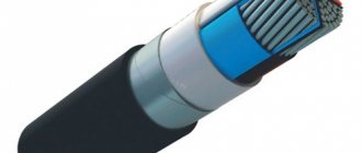
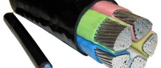
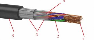
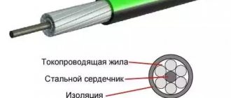
Design of the VVG cable product
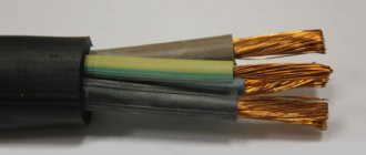
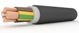
The structural composition of the cable with the abbreviation VVG is the following device:
- In the center there is a metal core that carries current, the material of which is copper. The vein can be round or sectoral in shape. It is common for multi-core cables of these types to contain a grounding or neutral conductor;
- The conductors can be distinguished by the bright colors on the shells: the grounding conductors are contained in light blue or light blue shells, and the grounding conductors are yellow-gray.
- A twist is formed from several cores, the voids of which are filled with insulating material;
- This structure is placed in a surface shell, which is made of a similar polyvinyl chloride.
Common Features for These Cables
According to clause 4.1 a)-e) GOST 31996-2012, the general characteristics for these VVG are:
clause 4.1 a) according to the material of current-carrying conductors: copper conductors (without designation);
clause 4.1 b) by type of insulation material of current-carrying conductors: insulation made of polyvinyl chloride plastic, including reduced fire hazard (B) ;
clause 4.1 c) by the presence and type of armor: unarmored (D) ,
clause 4.1 d) according to the type of material of the outer sheath or protective hose: made of polyvinyl chloride plastic, including reduced flammability or reduced fire hazard: outer sheath (B) ,
e) by the presence of a metal screen: without screen (no designation) ;
Specifications
Unom - from 0.66 to 1 kV; Frequency - 50 Hz; Operating temperatures, t - from -50 °C to +50 °C; Air humidity (at t0 +35 °C) – up to 98%; Working life: up to 30 years; Warranty from the date of purchase: 5 years; Installation without heating: at temperatures from -15 °C;
Maximum heating:
- In stable mode: +70 °C;
- In emergency situations: +80 °C;
- With one core - 10;
- With several cores - 7.5.
Minimum bend radius:
Construction length:
- from 1.5 mm2 to 16 mm2 - 450 m.
- from 25 mm2 to 70 mm2 - 300 m.
- from 95 mm2 and above - 200 m.
More clearly in the table:
Application area
VVG cable is used for installation inside residential apartments and public buildings. Suitable for installing lighting lines, socket groups and powering individual household appliances with high power consumption, such as electric stoves, heating boilers, split systems and air conditioners and equipment with powerful electric motors.
VVG is designed for transmission and distribution of electricity with voltages of 0.66, 1, 3 and 6 kV, frequency 50 Hz, the cross-section of the wires depends on the amount of current consumed. Gasket is allowed:
- Outdoors, provided there is protection from UV rays and there is no danger of mechanical damage;
- By air on cables;
- Along the walls of buildings;
- On the surface of the earth;
- In dry rooms and with high humidity;
- In tunnels on cable ladders (cable ladders);
- In cable mines;
- In areas with increased fire hazard.
It is recommended to lay it underground only in metal, asbestos or plastic pipes.
Estimated weight for VVG cable
| Core cross-section, mm., External ? cable, mm. | Weight of 1 km cable, kg. | ||
| With copper core | With aluminum core | ||
| 1.5 2.5 4 6 10 16 25 35 50 70 95 120 150 185 240 | 10.7 11.8 14.0 15.3 17.4 20.3 24.6 27.4 31.8 34.8 38.8 42.0 46.2 50.2 56.6 | 170 231 343 456 674 1007 1537 2035 2844 3811 5051 6246 7763 9472 12235 | — 151 216 265 356 499 743 940 1301 1625 2120 2544 3135 3765 4831 |
Decoding of other types of VVGng cable
- VVG – interpretation: standard copper wire, does not spread flame when laid alone, has polyvinyl chloride insulation of the inner and outer layers;
- VVGNG hf – there are no halogens, the wire is used in group laying, taking into account the volume of flammable load for rooms filled with working computer and microprocessor equipment, as well as in rooms visited by a large number of people;
- VVG PNG - interpretation: core insulation is made of thermoplastic polyethylene, flat design, used for making wiring in industrial buildings, non-flammable;
- vvgng p – conductors are laid in one plane, used for laying in air on cable racks or blocks, without mechanical stretching;
- kvvgng ls - control cable, fixedly attached to electrical appliances, devices and clamp assemblies, can be laid externally, in cable ducts and indoors, works in aggressive conditions, ensures fire safety of cable communications in group installations;
- VVGNG-frls - VVGNG frls cable is an analogue of the VVGNG-LS sample, with increased fire resistance, this is confirmed by the decoding of the letters frls (Fire Resistance Low Smoke), characterized by reduced formation of smoke and gas, prevents combustion in group gaskets;
- nym cable – power wire, application: stationary installation inside industrial and domestic buildings of power and lighting lines. nym wires stand for “standard cable in the German classification with polyvinyl chloride insulation with an outer sheath.”
Weight and dimensions parameters of VVGNG cables include:
- number of cores;
- core cross-section in mm²;
- outside diameter;
- wire weight, kg/km. Gngi
An example of the weight and size parameters of a 3×1 5, 3×1 wire: number of cores 3 pieces, core cross-section 1.5 mm².
The weight of the VVGNG cable for current with an operating voltage of 660 V and 1000 V differs by several kilograms.
For example: 1 km of wire VVGNG 3×1 5 for a current voltage of 660 V weighs 96 kg, and for 1000 V - 122 kg.
What are the problems when using a cable?
Over time, the insulation material wears out, which also affects the physical and chemical properties of the power cable.
The main factors influencing the aging process of insulation are:
- mechanical loads (vibrations, electrodynamic forces);
- chemical exposure to aggressive substances;
- moisture ingress;
- oxidation and regular heat exposure;
- overvoltage.
Problems cannot be ruled out when laying the wire.
Different types of insulation also exhibit aging in their own way. Solid dielectrics are destroyed, microcracks appear on their surface, organic ones emit gases, and the impregnation of paper insulation changes its physical and chemical properties.
The aging process is natural and irreversible, but it can be delayed. To do this, it is necessary to strictly follow all the manufacturer’s instructions for the wiring process and operating mode.
Systematic overheating of the power wire leads to rapid aging of the material. To avoid this, do not lay the cable near heat sources. It is advisable only to use the type of cable recommended by the manufacturer for the work (for example, rubber is not suitable for transmitting high voltage).
Important! It is necessary to use a wire with a suitable conductor cross-sectional area. Incorrect calculations lead to rapid wiring failure.
Laying methods
The VVG cable can be used in the construction of various objects, as well as in underground trenches.
The laying method directly depends on the specific purpose. The conductor can be laid on various surfaces consisting of non-combustible materials. These include concrete, plaster, brick or plaster. The VVG cable can be laid openly under a variety of suspended structures. A prerequisite is the exclusion of any mechanical influences. If there is a possibility of damage to the conductor, you need to think about additional protection. Often, special channels, tubes, metal or corrugated hoses are used for this.
Protective elements are also installed when the wire is laid on objects consisting of flammable materials.
The most popular is the hidden method. It is often used in residential premises when the cable is laid under plaster. First you need to make grooves in the walls , and then treat the product with cement plaster. In such situations, the possibility of mechanical impacts is eliminated, so there is no need to use additional protection. The only exception is when the wire is laid in wooden buildings. This option can be used in structures made of fireproof materials, for example, in pipes.
There is no wire that can be laid underground without the use of special protective elements. This is due to the fact that the cable needs to be preserved for a long period, but it itself is not equipped with built-in protection. Because of this, certain elements of protection against mechanical damage are used. In most cases they are sealed boxes.
Open position
If you study the technical parameters of the cable, you can conclude that installation is allowed in surfaces made of difficult-to-flammable or non-flammable materials, for example brick, concrete, gypsum or plaster. In an open way, VVG wire can be laid under various suspended structures , such as cables and the like.
In this case, the gasket must be very reliable. Any mechanical influences should be excluded. If the cable may be damaged, additional protection must be provided. Usually, special channels, metal hoses, corrugated hoses or tubes are used for this purpose. Protection is installed if the open installation method is carried out on flammable objects, built, for example, from wood.
Hidden option
This installation method is the most popular and is used in residential premises. The wire is usually laid under the plaster. Until this point, grooves are made in the walls, and after that the cable is covered with plaster and cement. In this case, mechanical damage is excluded, and therefore there is no need to apply additional protection. The exception is when the cable is laid in wooden houses. Hidden gasket can be used in various fireproof materials, for example, in pipes.
Location underground
No type of cable can be laid underground without the use of special protection. This is because the wire needs to be preserved for a long time, but it itself is not equipped with built-in protection. That is why protective measures are taken against various mechanical damages. For underground installation, sealed boxes are used.
Design features
Cable VVG PNG (A): decoding
The flexibility of a multi-core cable increases with the number of wires per certain cross-sectional area, S. For example, a cable consisting of 10 cores, total S = 5 mm², has less flexibility and resistance to kinks than a 50-core cable with the same cross-section. But the latter oxidizes faster and corrodes, which increases the internal resistance and wear of the cable.
Stranded and solid wires
This property must be taken into account to achieve optimal results when choosing. For stationary wiring, it is better to use a cable with cores consisting of one current conductor. If it is subject to large bends during operation, then it is better to use a stranded one from a small number of strands (for example, carriers, extension cords).
Flat cable is more often used as power conductors. Since its wires are arranged in a row, this reduces the parasitic effect between the electrodes, which is noticeable under heavy loads.
VVGng(A), VVGng
View prices → Cables VVGng(A) and VVGng - power cables identical in design are manufactured in accordance with GOST R 53769-2010.
Description
Cable VVGng(A), VVGng - power cable consists of copper cores in polyvinyl chloride insulation, enclosed in a PVC sheath. Does not propagate combustion when laid in bundles. The cables are intended for the transmission and distribution of electrical energy in stationary installations at a rated alternating voltage of 0.66 kV and 1.0 kV at a frequency of 50 Hz.
Cable design VVG(A)ng and VVGng:
- Copper current-carrying conductor: - single-wire (class 1) with a cross-section of 1.5-50 sq. mm - “ozh”, - multi-wire (class 2) with a cross-section of 50-240 sq. mm;
- PVC insulation, - color marking: white or yellow, blue or green, red or crimson, brown or black, - digital marking for cables with a cross-section of 70 sq. mm and above: 1, 2, 3, 4, 0;
- Winding made of non-woven fabric for multi-core cables with a core cross-section of 16 sq. mm and above;
- Sheath made of PVC plastic compound of low flammability.
Explanation of cable VVG(A)ng and VVGng:
B - vinyl insulation B - vinyl shell G - without armor (bare) ng - does not support combustion
Characteristics
Conditions for laying and operating cables VVG(A)ng and VVGng:
The cables are designed for use in areas with temperate, cold and tropical climates, on land, rivers and lakes at altitudes up to 4300 m above sea level. — in the air in the absence of danger of mechanical damage during operation; - for installation in dry or damp rooms (tunnels), channels, cable mezzanines, shafts, collectors, industrial premises, partially flooded structures in the presence of an environment with weak, medium and high corrosive activity; — for laying on special cable overpasses, over bridges and in blocks; - for installation in fire hazardous areas; - for installation in explosive zones of class B-Ib, B-Ig, B-II, B-IIa;
The permissible heating of the conductors in emergency mode should not exceed +80°C and the duration of operation in emergency mode should not be more than 8 hours per day, but not more than 1000 hours over the service life.
Group characteristics
Power cables with plastic insulation for low voltage
This group includes cables with aluminum or copper conductors with plastic insulation in a plastic sheath, with or without protective covers, intended for the transmission and distribution of electricity in stationary installations at a rated alternating voltage of 0.66 - 6 kV with a frequency of 50 Hz at ambient temperature from -50°С to +50°С.
Brands, design elements and applications
| Cable brand | Core material A - aluminum M - copper | Insulation P - polyethylene B -PVC plastic | Shell P - polyethylene B -PVC plastic compound Vng - PVC plastic compound of reduced flammability | Protective cover (section 4.1) |
| APVG | A | P | IN | absent |
| AVVG | A | IN | IN | absent |
| VVG | M | IN | IN | absent |
| AVVGng | A | IN | Vng | absent |
| VVGng | M | IN | Vng | absent |
| AVVGz | A | B (with filling) | IN | absent |
| VVGz | M | B (with filling) | V | absent |
| AVBbShv | A | IN | absent | BbShv |
| VBBShv | M | IN | absent | BbShv |
| AVBbShng | A | IN | absent | BbShng |
| VBBShng | M | V | absent | BbShng |
| AVVB | A | V | IN | B |
| VVB | M | V | IN | B |
| AVVBG | A | V | IN | BG |
| VVBG | M | V | V | BG |
The basic brands in this group of cables are APVG, AVVG, VVG, AVVGz, VVGz, AVBbShv, VBBShv. Cables are produced in accordance with GOST 16442-80.
APVG, AVVG, VVG cables are intended for installation in dry and wet industrial premises, on special cable racks, and in blocks. At the same time, cables of the AVVGz and VVGz brands are used for power supply to electrical installations that require cable sealing during entry, and they are recommended for laying in the ground with low corrosive activity and the absence of the possibility of mechanical damage and tensile forces.
Cables of the AVBbShv and VBBShV brands are intended for all of the above applications (except for laying in blocks), but if there is a risk of mechanical damage during operation.
To the designation of cable brands AVVG, VVG, AVBbShv VBBShV in tropical design, add the letter “T” through a hyphen, for cables with single-wire conductors - the letter “ozh” in brackets, for cables in flat design - through a hyphen, the letter “P”
Cables of the AVVGng, VVGng, AVBbShng and VBBShng brands differ from the basic brands in that the sheath or hose is made of low-flammability PVC plastic and are used to ensure the fire safety of cable chains when laid in bundles.
Cables of brands AVVB, VVB, AVVBG, VVBG differ from cables of brands AVVG and VVG in the presence of protective covers of type B and BG and are intended mainly for the same areas of application as cables of brands AVBbShv and VBbShv.
Design parameters
The number of cores in the cables, the range of nominal cross-sections of the cores and rated voltages are indicated in the table.
| Cable brand | Number of cores | Nominal core cross-section, mm2 | |||
| Rated cable voltage, kV | |||||
| 0,66 | 1 | 3 | 6 | ||
| VVG | 1,2,3 and 4 | 1,5-50 | 1,5-240 | — | — |
| VVGz | 2,3 and 4 | 1,5-50 | 1,5-50 | — | — |
| AVVG, APVG | 1,2,3 and 4 | 2,5-50 | 2,5-240 | — | — |
| AVVGz | 2,3 and 4 | 2,5-50 | 2,5-50 | — | — |
| AVBbShv, VBBbShv | 2,3 and 4 | 4-50 | 6-240 | 6-240 | — |
| AVVG, VVG, AVBbShv, VBBShv | 3 | — | — | — | 35-240 |
| AVVG, APVG | 5&6 | 2,5-50 | 2,5-35 | — | — |
| VVG | 5&6 | 1,5-25 | 1,5-25 | — | — |
For four-core cables, the largest nominal cross-section of the cores is 185 mm2.
Cables for voltages of 3 and 6 kV are made only with three cores. Two-core cables must have cores of the same cross-section. Three-, four- and five-core cables must have all conductors of the same cross-section or one conductor of a smaller cross-section (grounding or neutral conductor). Six-core cables must have four cores of equal cross-section and two wires of smaller cross-section.
The nominal cross-sections of neutral conductors (smaller cross-section) and grounding conductors must correspond to those indicated in the table.
Nominal sections of cores, mm2
| Basic | 1,5 | 2,5 | 4 | 6 | 10 | 16 | 25 | 35 | 50 | 70 | 95 | 120 | 150 | 185 | 240 |
| Zero | 1,5 | 1,5 | 2,5 | 4 | 6 | 10 | 16 | 16 | 25 | 35 | 50 | 70 | 70 | 95 | 120 |
| Grounding | 1,0 | 1,5 | 2,5 | 2,5 | 4 | 6 | 10 | 16 | 16 | 25 | 35 | 35 | 50 | 50 | 70 |
Current-carrying conductors can be single-wire or multi-wire in accordance with the table and must comply with classes 1 and 2.
| Core name | Nominal core cross-section, mm2 | |||
| round | shaped | |||
| copper | aluminum | copper | aluminum | |
| Solid wires | 1,0-50 | 2,5-240 | 25-50 | 25-240 |
| Stranded cores | 16-240 | 25-240 | 25-240 | 25-240 |
The current-carrying conductors of single-core cables of all cross-sections and multi-core cables with a cross-section of up to 16 mm2 must be round in shape. Conducting conductors of belt-insulated cables with a cross-section of 25 mm2 or more must be sector or segment shaped.
The radius of curvature of single-wire sector cores must be at least 0.5 mm.
It is allowed to manufacture cables with round conductors with a cross-section of up to 50 mm2.
The conductors are insulated, depending on the brand, with PVC plastic or polyethylene. The current standard provides for insulation made of cross-linked polyethylene (designation Pv).
The insulated cores of multi-core cables must have a distinctive color. The insulation of the neutral conductors should be blue (light blue).
The insulation of the grounding conductors must be two-color (green-yellow), with one color covering at least 30 and no more than 70% of the insulation surface, and the other the rest.
The color marking must be continuous or in the form of a longitudinal stripe with a width of at least 1 mm.
It is allowed to mark cores insulated with polyvinyl chloride plastic with numbers, starting from zero. Marking with numbers is done by embossing or printing. The height of the numbers is at least 4.0 mm. The distance between numbers should not be more than 35 mm.
The insulation of single-core cables can be of any color.
Cable insulation thickness, mm
| Rated voltage, kV | Nominal core cross-section, mm2 | Insulation made of polyethylene or polyvinyl chloride plastic | XLPE insulation |
| 0,66 | 1-2,5 | 0,6 | 0,7 |
| 4 and 6 | 0,7 | 0,7 | |
| 10 and 16 | 0,9 | 0,7 | |
| 25n35 | 1,1 | 0,9 | |
| 50 | 1,3 | 1,0 | |
| 1 | 1-2,5 | 0,8 | 0,7 |
| 4-16 | 1,0 | 0,7 | |
| 25 and 35 | 1,2 | 0,9 | |
| 50 | 1,4 | 1,0 | |
| 70 | 1,4 | 1,1 | |
| 95 | 1,5 | 1,1 | |
| 120 | 1,5 | 1,2 | |
| 150 | 1,6 | 1,4 | |
| 185 | 1,7 | 1,6 | |
| 240 | 1,9 | 1,7 | |
| 3 | 6-240 | 2,2 | 2,0 |
| 6 | 10-240 | 3.0 - for polyethylene | 3,0 |
| 3.4 - for polyvinyl chloride plastic compound |
Twisted insulated conductors must have gaps between them filled.
In cables of the AVVGz and VVGz brands, the PVC filling is applied simultaneously with the sheath and must be separated from the insulation and sheath without damage.
Cables with sector conductors, cables of the AVVG, APVG, VVG brands for voltages up to 1 kV inclusive, as well as cables of the AVBbShv and VBbShv brands with conductors with a cross-section of up to 25 mm2 inclusive can be without filling.
In cables of the AVVG, VVG, APVG brands for voltages up to 1 kV inclusive, a tape made of polyethylene terephthalate film or polyvinyl chloride plastic compound or other equivalent material and a sheath made of pressed-out polyvinyl chloride plastic compound must be overlapped over the twisted insulated conductors.
It is allowed to manufacture cables without tapes over twisted insulated cores, provided that the mobility of the insulated cores is maintained and the sheath can be separated from the insulation without damaging it.
In cables of all brands, except those indicated and brands AVVGz, VVGz, belt insulation must be applied over the twisted insulated cores.
The belt insulation must be pressed out of the insulation material or from polyvinyl chloride plastic compound or applied by winding or longitudinally with strips of polyethylene terephthalate film, polyvinyl chloride plastic compound or other equivalent material.
For cables with voltages up to 3 kV inclusive, belt insulation consisting of two strips of polyethylene terephthalate film and two strips of crepe paper is allowed.
The nominal thicknesses of PVC shells must correspond to category Obp-2
Reference values of outer diameters and weights of cables of individual standard sizes are indicated in the tables
Taking into account significant tolerances, actual values may differ by 5-10% down or up.
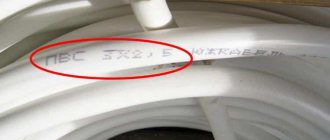
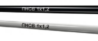
On the plastic sheath or protective hose, no more than every 300 mm, the distinctive index of the manufacturer and the year of manufacture of the cable must be applied.
Electrical Requirements
The cables must withstand an alternating voltage test with a frequency of 50 Hz for 10 minutes. The test voltage values are given in the table.
| Rated cable voltage, kV | Test voltage value |
| 0,66 | 3 |
| 1 | 3,5 |
| 3 | 9,5 |
| 6 | 15 |
Electrical insulation resistance of cables, MOhm
| Core cross-section, mm2 | Electrical resistance, MOhm |
| With PVC insulation for voltage 0.66 and 1 kV | |
| 1 and 1.5 | 12 |
| 2,5-4 | 10 |
| 6 | 9 |
| 10-240 | 7 |
| With PVC insulation for voltage 3 kV | |
| 1 — 240 | 12 |
| With PVC insulation for voltage 6 kV | |
| 1 — 240 | 50 |
| With polyethylene insulation | |
| 1 — 240 | 150 |
Outer diameters of cables for voltage 0.66 kV, mm
| Nominal core cross-section, mm2, nx S | AVVG, VVG | AVBbShv, VBBbShv |
| 1x1.5 | 5,0 | — |
| 1x2.5 | 5,5 | — |
| 1x4 | 6,1 | — |
| 1x6 | 6,6 | — |
| 1x10 | 7,8 | — |
| 1x16 | 9,3 | — |
| 1x25 | 11 | — |
| 1x35 | 12 | — |
| 1x50 | 14 | — |
| 2x1.5 | 7,6 | — |
| 2x2.5 | 9,1 | — |
| 2x4 | 10,5 | 15 |
| 2x6 | 11,5 | 16 |
| 2x10 | 14 | 19 |
| 2x16 | 16 | 20 |
| 2x25 | 19 | 24 |
| 2x35 | 21 | 26 |
| 2x50 | 25 | 29 |
| 3x1.5 | 8,0 | — |
| 3x2.5 | 9,5 | — |
| 3x4 | 11 | — |
| 3x6 | 12 | 16 |
| 3x10 | 14,5 | 17 |
| 3x16 | 17 | 19 |
| 3x25 | 20,5 | 21 |
| 3x35 | 23 | 25 |
| 3x50 | 27 | 31 |
Weights of cables for voltage 0.66 kV, kg/km
| Nominal cross-section of cores, mm2 | AVVG | VVG | AVBbShv | VBBShv |
| 1x1.5 | — | 37 | — | — |
| 1x2.5 | 35 | 51 | — | — |
| 1x4 | 45 | 70 | — | — |
| 1x6 | 55 | 91 | — | — |
| 1x10 | 80 | 140 | — | — |
| 1x16 | 115 | 215 | — | — |
| 1x25 | 160 | 320 | — | — |
| 1x35 | 200 | 420 | — | — |
| 1x50 | 260 | 570 | — | — |
| 2x1.5 | — | 67 | — | — |
| 2x2.5 | 75 | 105 | — | — |
| 2x4 | 97 | 140 | 320 | 370 |
| 2x6 | 120 | 190 | 360 | 440 |
| 2x10 | 170 | 290 | 460 | 590 |
| 2x16 | 220 | 410 | 550 | 750 |
| 2x25 | 330 | 630 | 700 | 1050 |
| 2x35 | 400 | 820 | 810 | 1300 |
| 2x50 | 560 | 1200 | 1050 | 1700 |
| 3x1.5 | — | 90 | — | — |
| 3x2.5 | 90 | 140 | — | — |
| 3x4 | 120 | 200 | 360 | 440 |
| 3x6 | 150 | 260 | 400 | 520 |
| 3x10 | 220 | 410 | 520 | 710 |
| 3x16 | 290 | 600 | 630 | 940 |
| 3x25 | 440 | 810 | 830 | 1300 |
| 3x35 | 550 | 1300 | 1000 | 1700 |
| 3x50 | 760 | 1700 | 1300 | 2200 |
Outer diameters of cables for voltage 1 kV, mm
| Nominal cross-section of cores, mm2 | AVVG, VVG | AVBbShv, VBBbShv |
| 1x1.5 | 5,4 | — |
| 1x2.5 | 5,8 | — |
| 1x4 | 6,7 | — |
| 1x6 | 7,2 | — |
| 1x10 | 8 | — |
| 1x16 | 9,5 | — |
| 1x25 | 11 | — |
| 1x35 | 12 | — |
| 1x50 | 14 | — |
| 1x70 | 17 | — |
| 1x95 | 19 | — |
| 1x120 | 21 | — |
| 1x150 | 23 | — |
| 1x185 | 25 | — |
| 1x240 | 28 | — |
| 2x1.5 | 8,4 | — |
| 2x2.5 | 10 | — |
| 2x4 | 11,5 | — |
| 2x6 | 12,5 | 17 |
| 2x10 | 14 | 19 |
| 2x16 | 16 | 21 |
| 2x25 | 20 | 24 |
| 2x35 | 22 | 26 |
| 2x50 | 25 | 30 |
| 3x1.5 | 9,4 | — |
| 3x2.5 | 10,5 | — |
| 3x4 | 12 | — |
| 3x6 | 13 | 18 |
| 3x10 | 15 | 20 |
| 3x16 | 17 | 22 |
| 3x25 | 21 | 25 |
| 3x35 | 23 | 28 |
| 3x50 | 27 | 31 |
| 3x70 | 29 | 33 |
| 3x95 | 32 | 37 |
| 3x120 | 36 | 40 |
| 3x150 | 39 | 44 |
| 3x185 | 43 | 47 |
| 3x240 | 49 | 53 |
Weights of cables for voltage 1 kV, kg/km
| Nominal cross-section of cores, mm2 | AVVG | VVG | AVBbShv | VBBShv |
| 1x1.5 | — | 42 | — | — |
| 1x2.5 | 39 | 55 | — | — |
| 1x4 | 55 | 80 | — | — |
| 1x6 | 60 | 100 | — | — |
| 1x10 | 80 | 145 | — | — |
| 1x16 | 120 | 220 | — | — |
| 1x25 | 165 | 320 | — | — |
| 1x35 | 200 | 420 | — | — |
| 1x50 | 270 | 580 | — | — |
| 1x70 | 340 | — | — | — |
| 1x95 | 430 | — | — | — |
| 1x120 | 530 | — | — | — |
| 1x150 | 630 | — | — | — |
| 1x185 | 760 | — | — | — |
| 1x240 | 970 | — | — | — |
| 2x1.5 | — | 80 | — | — |
| 2x2.5 | 85 | 120 | — | — |
| 2x4 | 115 | 170 | — | — |
| 2x6 | 135 | 210 | 400 | 480 |
| 2x10 | 175 | 300 | 470 | 590 |
| 2x16 | 230 | 430 | 560 | 770 |
| 2x25 | 340 | 660 | 720 | 1050 |
| 2x35 | 420 | 860 | 850 | 1300 |
| 2x50 | 580 | 1200 | 1050 | 1700 |
| 3x1.5 | — | 115 | — | — |
| 3x2.5 | 105 | 155 | — | — |
| 3x4 | 145 | 220 | — | — |
| 3x6 | 170 | 290 | 460 | 570 |
| 3x10 | 230 | 420 | 540 | 730 |
| 3x16 | 300 | 610 | 650 | 960 |
| 3x25 | 450 | 930 | 850 | 1300 |
| 3x35 | 560 | — | 1000 | 1700 |
| 3x50 | 780 | 1200 | 1300 | 2200 |
| 3x70 | 1050 | 1700 | 1600 | 2900 |
| 3x95 | 1350 | 2400 | 2000 | 3800 |
| 3x120 | 1650 | 3100 | 2300 | 4600 |
| 3x150 | 2000 | 3900 | 2700 | 5600 |
| 3x185 | 2400 | 4800 | 3200 | 6700 |
| 3x240 | 3100 | 5900 | 3900 | 8500 |
terms of Use
Permissible operating temperatures, °C
| Type of cable insulation | Long-term permissible core heating temperature | Maximum permissible temperature at short circuit currents |
| Polyvinyl chloride plastic compound | 70 | 160 |
| Polyethylene | 70 | 130 |
| Cross-linked polyethylene | 90 | 250 |
The shelf life of cables in open areas is no more than 2 years, under a canopy - no more than 5 years, in enclosed spaces - no more than 10 years.
← Back
What to look for when choosing
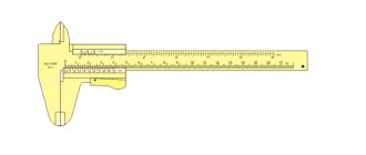
Despite the difficulty of counterfeiting electrical cables, it is still possible to come across low-quality products in which the insulation does not meet the standards or the cross-section of the conductors is less than that indicated on the marking. To check the insulation, just look for the presence or absence of drips - a good wire will have a clean, even cut with the insulation of a tight-fitting core. To check the cross-section, you can use a micrometer or the “old-fashioned” method, when the core is folded into 10 layers and measured with a ruler. For the rest, you need to focus on the calculated indicators and select a cable of the required cross-section.
Device
The VVG cable is equipped with a copper or aluminum current-carrying conductor from one to five. Depending on what version is available, the stranded electrical cable can be monolithic or multi-core.
Cable design features
Each core is covered with an insulating polyvinyl chloride sheath and a special dye for identifying the wire in electrical applications by color marking. The design is standard. It has a round and flat shape.
Outer diameters of cables for voltage 0.66 kV, mm
| Nominal core cross-section, mm2, nx S | VVG |
| 1x1.5 | 5,0 |
| 1x2.5 | 5,5 |
| 1x4 | 6,1 |
| 1x6 | 6,6 |
| 1x10 | 7,8 |
| 1x16 | 9,3 |
| 1x25 | 11 |
| 1x35 | 12 |
| 1x50 | 14 |
| 2x1.5 | 7,6 |
| 2x2.5 | 9,1 |
| 2x4 | 10,5 |
| 2x6 | 11,5 |
| 2x10 | 14 |
| 2x16 | 16 |
| 2x25 | 19 |
| 2x35 | 21 |
| 2x50 | 25 |
| 3x1.5 | 8,0 |
| 3x2.5 | 9,5 |
| 3x4 | 11 |
| 3x6 | 12 |
| 3x10 | 14,5 |
| 3x16 | 17 |
| 3x25 | 20,5 |
| 3x35 | 23 |
| 3x50 | 27 |
Varieties
The popularity of this type of product leads to the emergence of various types of execution. Additional characteristics that the VVG cable receives are determined by decoding the marking parameters. Here are the main varieties that a consumer may encounter.
Fireproof version:
- Wires that are non-flammable when laid alone do not have special markings;
- Non-flammable in a group installation method are designated by the index “ng”. Subcategories: ng(A), ng(B), ng (A F/R), indicate the fire resistance category;
- Non-flammable, with a group installation method, with low smoke and gas emissions, received the ng-LS marking;
- Those that do not emit abrasive and corrosive substances during smoldering and fire are designated ng-HF;
- Flame-resistant, for group installation, with low gas and smoke emissions - ng-FRLS;
- Flame-resistant, non-flammable, non-corrosive and non-abrasive - ng-FRHF;
Division according to the design of the conductive part:
- Single core(o);
- Stranded (m);
- Round section (k);
- Profile core of segmental cross-section (c).
In detail, the designations used when marking cable products can be found in GOST 31966–2012. When purchasing cable products yourself, a preview of this document will allow you to navigate its types and speak on an equal footing with the seller.
Wire testing
To put a flame retardant mark on a wire, it is necessary to test the wire in various ways.
To carry out the test, the conditions of a real fire are recreated in laboratory conditions. After this, the laboratory technician uses special equipment to measure the transparency of the air inside the room with the fire. These measurements must be taken both under normal conditions and after a fire. Smoke will reduce the light transmission of the room, and this will be recorded by the device. As a result, a trained worker will calculate the ratio of light transmittance before the experiment, as well as after the fire. For the wire to successfully pass the test, the change in transparency inside the room should be no more than 40%. Only in this case will it be possible to put the appropriate designation on the cable.
Operating and storage conditions
Standard operational properties of the described cable lie within the ambient temperature range from -50°C to +50°C. At the same time, it can heat up to +70°C, and does not lose functionality during short-term overload up to +90°C. Damage can occur when the conductors are heated to +160-280°C.
Interesting. When purchasing a cable, it is better to choose the material with the latest release date. This will help avoid deterioration in quality due to possible improper storage. This is especially true for stranded ones with thin conductors, which are more susceptible to corrosion.
It is better to store the cable in the same temperature range as it is used, with air humidity up to 98%. It must be wound and tied into a roll or coil, laid on a dry base. Storing the material in conditions close to the maximum permissible limits sharply reduces its shelf life.
Unwound cable
Important! Improper storage of an unwound cable with accidental exposure to moisture and chemically active substances leads to focal damage. It is not advisable to use material that has previously been tangled in knots or has been damaged by corrosion. This can lead to its early failure, fire or damage to the equipment powered by it.
Properly rolled storage material
The type of cable described is the most common among household users. Relatively high technical characteristics are combined with a relatively low price.
What it is
A power cable is a single-core or multi-core electrical product that is needed to supply electrical energy to stationary consumers. Used in a private house, apartment, cottage or mobile equipment. The cable connects the main distribution board or power line to the end-user portion. Regardless of the technical characteristics, the power cable consists of a metal core with an insulating layer and an outer sheath, which protects the entire cable structure.
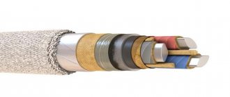
Note! The VVG power cable differs from the VVGPG in that it is supplemented with various elements, for example, external belt insulation, a shielding layer and armor. The design depends on the function with the scope of application of the source.
VVG is a cable element having an aluminum or copper conductor, a polyvinyl chloride or polyethylene insulating layer, a lead/aluminum/polyethylene/polymer or polyvinyl chloride layer of the core sheath. Also includes armor protection, shielding and additional characteristics in the form of combustion and low smoke emission.
VVG cable as the main type of repair of private construction
VVG decoding looks like this: B - insulating polyvinyl chloride core, B - polyvinyl chloride sheath and G - protective armor sheath. The conductor can be single-core or stranded. In private homes, the first type is used. The cable can be round or flat, neutral or phase.
What does vvg mean and how does it stand for?
Life time
Service life is 30 years from the date of manufacture of the cables. The warranty period is 5 years from the date of commissioning of the products, but no later than 6 months from the date of manufacture.
Operational life
Storage conditions and periods:
- open premises - up to 2 years;
- under a canopy - no more than 5 years;
- closed premises - no more than 10 years.
Outer diameters of cables for voltage 1 kV, mm
| Nominal cross-section of cores, mm2 | VVG |
| 1x1.5 | 5,4 |
| 1x2.5 | 5,8 |
| 1x4 | 6,7 |
| 1x6 | 7,2 |
| 1x10 | 8 |
| 1x16 | 9,5 |
| 1x25 | 11 |
| 1x35 | 12 |
| 1x50 | 14 |
| 1x70 | 17 |
| 1x95 | 19 |
| 1x120 | 21 |
| 1x150 | 23 |
| 1x185 | 25 |
| 1x240 | 28 |
| 2x1.5 | 8,4 |
| 2x2.5 | 10 |
| 2x4 | 11,5 |
| 2x6 | 12,5 |
| 2x10 | 14 |
| 2x16 | 16 |
| 2x25 | 20 |
| 2x35 | 22 |
| 2x50 | 25 |
| 3x1.5 | 9,4 |
| 3x2.5 | 10,5 |
| 3x4 | 12 |
| 3x6 | 13 |
| 3x10 | 15 |
| 3x16 | 17 |
| 3x25 | 21 |
| 3x35 | 23 |
| 3x50 | 27 |
| 3x70 | 29 |
| 3x95 | 32 |
| 3x120 | 36 |
| 3x150 | 39 |
| 3x185 | 43 |
| 3x240 | 49 |
How to use it correctly
Suitable for installation in power plant, industrial plant, lighting, channel, tunnel and other sites. Due to the fact that it is resistant to combustion, it is widely used where there is a high probability of explosions with fire. Safe to use thanks to armor. It is worth pointing out that due to the gasket, it is recommended to provide protection using a cable duct, corrugation, metal sleeve and other things.
As for the moment of use, the place, period and conditions of safety of the conductor must be thought out. In an open area, the shelf life is several years, under a canopy - 5 years, and in a warehouse - 10 years.
It should be noted that the lower part must be brought out and secured with sheet metal. The top should be secured to the inside of the drum. Each end should be equipped with heat-shrinkable, moisture-proof mouth guards. If there is a metal shell, then its ends must be sealed or wrapped with PVC tape. Otherwise, plastic with rubber insulation will be fragile and may lose its own qualities.
Note! It is important to understand that laying outdoors is dangerous due to wind, frost and ultraviolet radiation. In this case, the cable should be protected from rupture as much as possible and secured to a steel cable. To prevent it from cracking, you should use corrugation. An excellent option would be to use a metal hose or polyamide corrugated pipe.
In general, the VVG cable is a conductor with a wide range of standard sizes, ease of installation and low cost. It is divided into 8 main varieties, each of which has its own design, functional mechanical and electrical parameters. It is used in all spheres of human activity according to special instructions.
Decoding and types
KG cable - decoding and technical characteristics
If the first letters of the abbreviation in the name of the cable brand do not begin with the letters AA (aluminum conductor with an aluminum sheath) or AC (aluminum with a lead sheath), then this is interpreted to mean that the conductors are made of copper. The first letter B of the abbreviation VVG means that the core insulation is made of vinyl (polyvinyl chloride or its derivatives can be used). The second letter B means that the common insulation sheath of the bundle of cores with insulation is also made of vinyl. The third letter G indicates the absence of armor.
Decoding the abbreviation
Regular VVG
It is used for installation of electrical wiring in blocks, channels and collectors, guardhouses and tunnels, in dry and semi-dry cool rooms with a relative humidity of no more than 98%. External use in the open air is also possible. In this case, you should avoid prolonged direct exposure to sunlight and, if necessary, apply protection from them. Without additional protection, laying it under plaster is undesirable.
Non-flammable VVGng
The additional letters “ng” in the name of the cable VVG ng mean that its insulation does not support combustion. Its use is advisable where it comes into contact with materials such as:
- wood products (wood, lining, plywood, fiberboard, chipboard);
- paper (wallpaper, cardboard);
- fabric (curtains, carpets).
Also, decoding of the VVGNG (a) cable is with increased fire safety. The degree of fire safety is expressed by indices (a), (b), (c), (d), where the initial letter (a) means the highest category, and then in descending order.
Explanation of the VVG ng ls marking - in case of fire it produces extremely little harmful gases and smoke. VVG ng lt has insulation, which during forced combustion does not emit toxic substances and gases, and VVG ng hf can be deciphered - during combustion it does not emit corrosive substances or halogens. How is VVG ng frls different? They differ in that they have increased fire resistance with low gas formation after combustion of the insulation.
Release forms
If such a cable is marked VVG Z, this means that the space between the metal core and the insulation is filled with synthetic non-hydrophobic fiber or powder. The VVGP brand will differ in that it has a flat shape.
Cable shape
The shape of the cable depends on the type and number of cores and can be:
- round;
- flat;
- triangular;
- rectangular;
- pentagonal.
The three-core VVG cable can be round, flat or triangular. The difference between the round ones is that the cores can have a segmented shape, most often consisting of a multi-core bundle of wires. This form of cores is used for three or four-core cables, which in general cross-section form a circle shape, and the cores form a segment shape. This allows you to maintain the density of the entire cable during an acute angle bend, the wire does not bunch up into knots.
Important ! The VVG cable can be bent into a circle with a radius up to 10 times greater than the radius of the wire itself.