Number and types of fuses. Thus, the larger the varistor you install, the better, as long as it fits in size.
Augmented network filter circuit Chokes together with capacitors are the main elements of the filter circuit.
You can do without a second capacitor by adjusting the parameters of the first; Important! Geyser Prestige reverse osmosis filter connection diagram. Geyser Prestige 2 connection diagram Geyser M They are shown below in the figures. This is where power surge protectors come into the picture!
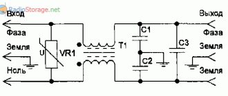
An extremely bright blue LED HL1 signals the presence of voltage and the serviceability of the filter, resistor R1 discharges capacitors C1, C2 when the filter is disconnected from the network. Thanks to the magnetic coupling between the windings of the inductors, common-mode interference is suppressed that is simultaneously induced or emitted by both network wires. Filters Designed to suppress interference. According to the diagram, the choke windings are connected in series, and the magnetic fields in them are mutually compensated.
In fact, it doesn’t matter where C2 is installed: before or after the contact components of the sockets, since their resistance is extremely low and has almost no effect on the output signal. In addition to interference, there may be voltage and current surges in the network, which can also damage expensive equipment.
HOW LC CIRCUIT WORKS - RESONANCE
What is a filter
A surge protector for a computer, washing machine and other household appliances is a device that protects a computer and other electronic equipment from voltage surges in the power supply network.
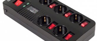
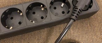
Photo – Modern filters
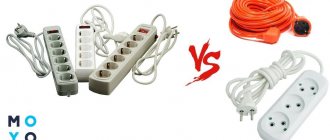
Many people think that network converters and extenders have a completely insignificant difference: while an extender simply splits the output signal into several ports, a filter is designed to protect computers, TVs and other electronics from alternating voltage, as well as interference with the power line. The main difference is that the filter can withstand not only constant loads, but also sudden circuits, lightning strikes, and can even work to save personal data during sudden lights out.
1.Assembling the pallet
General diagram of pallet assembly
So first of all, you need to screw the drain to the shower tray.
To do this, use silicone sealant. Apply sealant to the groove of the drain body, then install the gasket and apply sealant to its groove
Second, assemble the frame and screw the plastic legs onto it
Third, turn the pallet upside down and position the frame. Align the frame so that the legs do not protrude beyond the pallet inserts.
Using self-tapping screws, screw the frame to the pallet; the most important thing is not to mix up the length of the screws, so as not to pierce the pallet.
Fourth, file the outer leg if it protrudes beyond the pallet
Fifth, screw the front screen fasteners
At this point the pallet can be considered assembled. This is how all Triton pallets are assembled, both low, medium and high.
Description of the operating principle
A standard surge protector passes electrical current through a cable from the outlet to a number of electrical and electronic devices connected to the device. If the voltage from the outlet rises above the permissible level, the uninterruptible power supply device diverts additional electricity from the outlet to the ground wire.
The most common type of surge protector has a component called a metal oxide varistor, or MOV, that removes the extra voltage. The MOV forms the connection between the phase power line and the ground line.
The varistor itself consists of three parts: an oxide-metal part in the middle of the cable connecting to the power supply and grounding lines, which are made of two semiconductors. These semiconductor devices have variable resistance that varies with voltage. When the voltage is below a certain level, the electrons in the flux semiconductors combine in such a way as to create a very high resistance. If the voltage exceeds this level, the electrons behave differently, creating lower resistance. If the voltage matches the specified resolution, the varistor does nothing.
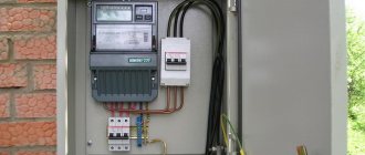
Photo - Main line filter
As soon as the additional current is diverted to the filter and to ground, the phase line voltage returns to normal levels. Thus, the surge protector Pilot (Pilot), Defender, and others only remove the pulse current, while allowing other devices connected to the conductor to continue operating at a normal rhythm. In other words, network noise suppressors operate like a pressure-sensitive valve that only opens when too much pressure is applied.
Photo – Professional filter circuit
AudioKiller's site
A long time ago, I noticed that when the refrigerator in the kitchen turned on/off, an unpleasant click sounded in the speakers of the stereo system. The problem was solved by installing capacitors in the sockets - this is where my “friendship” with surge protectors began. Nowadays, the 220 volt electrical network is heavily polluted with a lot of interference and short-term voltage surges that penetrate from the network and prevent the equipment from working properly. Filters are used to combat network interference. Cheap filters are not really filters, and expensive ones (like the quite decent Pilot filter) are too expensive, because you usually need several of them (I have about eight of them at home, constantly on). Therefore, a good option is to buy a cheap filter and remake it.
In principle, you can use a regular extension cord for modification, but usually there is no free space in the extension cord for the parts that need to be inserted into it. But there is free space in the extension cord with a switch (also a useful thing).
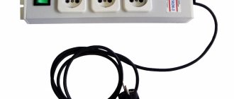
I recently urgently needed such a filter, I bought an extension cord at the nearest kiosk and modified it. Everything (including purchasing and photographing) took less than half a day. Here is the hero of our story:
Such devices are not actually surge protectors. There is only a varistor inside, limiting short-term high-voltage pulses that are sometimes present in the network (for a little about varistors , see Low-power power supply). That's all its filtering. Some devices (including mine) have a current switch that is supposed to open when a large current flows (never checked how they work). In this case, there is a button on the case that must be pressed to close the breaker again if it has tripped.
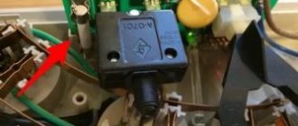
Let's disassemble the extension cord and see what's inside:
The number “14” written in blue marker doesn’t mean anything – that’s how it was originally. From it we can judge that this thing was not assembled by the Chinese - otherwise there would have been a hieroglyph! On the left there is a black fuska - a current breaker, to the right there is another black fuska (many wires go to it) - a switch. There is a varistor between them, but it is hard to see. At the intersection of the green and brown wires, the blue disk below is it. The red wires are soldered (check the quality of the soldering, it can be disgusting!) to long metal plates, which are the contacts.
Now we build the filter inside, and you're done. Here are diagrams of what was and what will be (the switch with a backlight bulb is not shown in the diagrams):
In the original diagram: Sc - current breaker, V1 - varistor type 471 (the number encodes the maximum voltage, and the maximum energy of the suppressed pulse depends on the diameter; diameter 6...10 mm is just that), the inscription “Extension cord” is precisely these contacts plates.
The modified version adds an RLC filter. It’s true that you won’t be able to make a good filter - there’s still not enough space, and you need to select parts for it. This is exactly what “Pilots” do - first they design a circuit, and then they make a body for it. But nevertheless, such a filter, assembled from scrap materials, works quite well.
Let's go through the elements. Coils L1 and L2 together with capacitors C1 and C2 form an LC filter. The resistance of the coils at high frequencies is high, but at low frequencies it is small. Therefore, in order to suppress low-frequency interference at least a little, resistors R1 and R2 are connected in series with the coils. Resistor R3 discharges the capacitors when disconnected from the network, otherwise the charged capacitors may receive a serious shock. Capacitor C2 is included on the other side of the contact plates in order to create a “distributed” capacitance so that the inductance and resistance of the plates do not impair filtering. In fact, in our case, the difference where C2 is turned on is not noticeable; the inductance and resistance of the contact plates are too small. But it’s still nice that we took care of it! And, besides, it is at that end of the case that there is free space where you can put this capacitor.
Sometimes there are disputes about the placement of resistors R1 and R2. How to turn them on - before the varistor, or after, like mine? It really depends on our goal. Before the varistor, resistors must be included if we want to improve the performance of the varistor when suppressing short-term high-voltage (up to several thousand volts) pulses. The varistor “passes these pulses through itself,” the current through the varistor reaches hundreds of amperes, and almost all of the pulse voltage drops at the resistance of the wires and contacts.
The resistance of the wires is quite small (after all, the better the network, the lower the resistance), and the current is very large. Therefore, with a large current on the varistor, a rather large voltage is obtained (left figure). If resistors R1 and R2 are placed in the path of the current, then their resistance (together 1...2 Ohms) is noticeably greater than the resistance of the wires, and the current will be much less (but still a hundred or two amperes!). And since the current is less, then the voltage on the varistor is less (right figure).
It would seem that the right option is much better! Not really. The fact is that these impulses are short-term, and most devices “do not notice” them (they are not uncommon on the network, have you noticed them?). What is a varistor for? Just in case of fire. You never know. 100 times the impulse will not have an effect, but on the 101st a larger impulse will come and burn the power supply, or something else. So, if this short-term impulse of 3000 volts is not always noticeable, is there a difference whether 300 volts or 600 will remain from it? (Attention! I took the numbers 300 and 600 “from a flashlight”! In fact, all this very much depends on the specific network, and on the specific varistor, and on the specific impulse! But the principle is correct!)
Why did I include resistors after the varistor? To separate the capacitors from the varistor as much as possible. A capacitor connected in parallel with the varistor does not even help it at all (sometimes it interferes, sometimes not). In addition, when the varistor limits enemy pulses, a bunch of high-frequency interference is formed, the voltage of which, although not high, is who needs it? By turning on the resistors after the varistor, I minimized the passage of interference to the filter output - after all, I got two stages of filtering - the varistor handles the high-voltage crap, and the coils with capacitors handle the rest, for which the resistors really help.
Conclusion. If you have a very “dirty” network, which often includes welding machines, place resistors before the varistor. If not, put them after . The question arises: why not include two pairs of resistors - one before the varistor. and the other after the varistor? For one simple reason - resistors get hot. Two pairs of resistors double the heating. And then something will melt or even catch fire! And installing low-resistance resistors (so that they heat up less) is also not a solution, they will work worse.
So, let's take the details
and figure out where to put them (more on the details themselves below):
Everything fits well, does not short out with anything, you can solder.
Capacitor C2 (on the right) must have long leads, otherwise it will not allow you to put the contact plates in place (although long leads impair the performance of the capacitor). Therefore, you don’t have to install it - it will be much easier to put everything back together.
When everything was put back together, nothing had changed in appearance, but the filling was completely different. To completely block the path of interference, we place a ferrite washer on the network cable near the extension cord itself (it’s most convenient to use a split washer with latches):
(This is ferrite on the other wire - the one I put on this extension cord is exactly the same, I just forgot to take a photo, and then it was too far to get it)
More on this. Unlike normal energy transfer, when current flows into the load through one wire and returns back to the source through the other, high-frequency (RF) interference can propagate through two wires at once. For example, when lightning strikes near electrical wires, a current arises in them, which flows immediately through both wires into the device, and, having passed through it, through the capacitance between the housing and the ground, is shorted to the ground.
Those. both network wires for interference are like two parallel forward wires (or like an antenna), and the ground is the return wire. Inside the device, RF interference current can affect various circuits and interfere with their life. By attaching a ferrite ring to a network wire, we increase its (wire) inductance, and hence the resistance at high frequencies. Therefore, the interference current will become less.
Construction and details
The scheme is very picky about details. But still some rules must be followed. Let's take it in order.
Varistor . Type 471. Diameter 6…10 mm. This is optimal.
Resistors R1, R2. The greater their resistance, the better the filtration, but more heating and more voltage loss. On the other hand, heating and voltage drop are greater, the greater the current (and power) consumed. Therefore, we select the resistance of the resistors depending on the total power consumed by all those devices that will be connected to the filter:
| Load power, W | up to 250 | up to 380 | up to 500 |
| Resistances R1 and R2, Ohm | 0,82 | 0,36 | 0,22 |
If you plan to connect more powerful consumers, you may have to abandon resistors altogether. On the other hand, why make a filter to connect an iron to?!
Resistors are used with a power of 5 W. You can take two-watt ones, but it’s not worth it - they should have a reserve of power in case the current suddenly turns out to be greater than expected (or the interference slips through, where its energy is released?..).
Chokes L1 and L2. These are the most “hard to get” elements. But on the other hand, since resistors work together with them, the requirements for chokes are reduced. The requirements are:
- Ferrite core. A coil without a core has too low inductance (given its actual dimensions), and a steel core does not work well at HF.
- The core is not closed, or with an air gap - otherwise the core may become saturated, and the inductance will greatly decrease.
- The maximum coil current (this is the current at which the inductance begins to decrease due to core saturation) is no less than the load current.
- The inductance of the inductor is at least 10 μH. The more, the better (up to 10 mH).
- The chokes are not magnetically coupled.
Capacitors C1, C2. If it is not possible to install C2, then it is quite possible to limit yourself to one capacitor. Since they are connected in parallel, it is quite possible to consider them as one capacitor with a capacitance equal to the sum of capacitances C1 and C2. Capacitor requirements:
- Film capacitor, type K73-17 or similar (imported ones are smaller in size).
- The capacity is not less than 0.22 µF. More than 1 µF is also not needed.
- Voltage 630 volts. Why so much? And this is a reserve, because when there is interference, the voltage increases. And according to the rules, the voltage on the capacitor should be less than the maximum permissible.
Resistor R3. Its power is 0.5 W, although it emits 10 times less. 220 volts are applied to this resistor, and it must have fairly large geometric dimensions (hence the 0.5 W) to withstand such voltage. Resistance from 510 kOhm to 1.5 MOhm.
That's all. You can use it, and good luck in the fight against interference!
At the request of readers, I measured how much the filter suppresses interference. This didn’t work out very well - it’s difficult for me to generate high-voltage pulses at home, and I didn’t do it. But the generator produced HF interference (small amplitude, but what's the difference?). Here are two tests. They may not be very accurate - the amount of suppression may be somewhat underestimated. A soldering iron was included as a load in the filter.
The first test is 30 kHz frequency suppression. This frequency is often used in switching power supplies (computer ones, for example), and the network is “clogged” with this frequency. Here are the voltage waveforms at the input and output:
Blue is input, red is output. The scales are the same. Suppression times 8, which is very good for a simple filter, especially one made from scrap materials.
The second test is really high frequency interference at 200 kHz:
Here the output voltage is 100 times larger than the input voltage. Interference suppression approximately 350 times!!! So RF interference will not get through.
New!
There are some good reels on sale:
They are wound with a fairly thick wire on a ferrite core, shaped like a dumbbell. There is a heat shrink tube on the outside. These coils have a fairly large inductance with a decent current (and several standard sizes - the larger the size, the greater the product of inductance and maximum current). Having such coils, making filters is a pleasure. The circuit is almost the same, now the coils are “powerful” and resistors in the interference suppression circuit are not needed:
In principle, everything remains the same, but except for the coils, the capacitor has changed. This is a specialized capacitor designed to work in filters (these are found in computers and uninterruptible power supplies. And the voltage of 280 V for which the capacitor is designed is the effective value of alternating current (this is indicated by the “280V ~” sign on the case). The same as 220. That is, you don’t need to divide the voltage written on the capacitor by the root of 2 to find out what maximum AC voltage it can be turned on at. Just 280 volts. And we have 220, a decent margin. That’s what happened :
Blue - varistor, which was in this “filter” extension cord; next to it there are black coils; according to good practice, they should be placed so that their axes are perpendicular, but first I took a photo, then bent the coil (the bottom one in the photo), then twisted everything, and only then I remembered that I took the photograph incorrectly! I was too lazy to take it apart again, sorry! Yellow is a capacitor. As far as I have met them, they are all yellow.
The resistor that discharges the capacitor is not installed here - a device will be connected to this filter all the time, which will discharge the capacitor. And if I take off this filter once in my life, I won’t forget to discharge it. I would just be too lazy to look for and solder a resistor, but I categorically recommend that everyone not take my example in this and install the resistor!
That's all! Very simple and very good!
18.08.2007 — 24.04.2008
Total Page Visits: 11850 — Today Page Visits: 24
How to choose a surge protector
Choosing network voltage stabilizers, filters and extension cords is not as easy as it seems. Experts identify several criteria that the device must meet:
- Consider how many ports the network extender should have. It is advisable that the devices have as many branches as possible, this will significantly save your time, reduce the number of cables in the apartment, and increase safety;
- All amplifiers have a certain limit of noise suppression, surge protection and power load capacity. It is especially important in this regard to calculate gateway devices and their characteristics. Also, think in advance how you will connect the splitter; you cannot turn on several powerful appliances at the same time (washing machine, hydrobox, air conditioners and stove);
- Check for UL gasket, make sure it is "transient surge voltage suppressors". Be sure to find out if the device is certified with the UL 1449 quality laboratory mark;
- Specify the purpose of the device: this is an extension cord for a computer, washing machines with water protection or audio equipment;
- Check the warranty and repair certificate. Some transformer single-phase and three-phase voltage stabilizers can catch fire due to overvoltage, but if they are certified, this should not happen.
3.Installing glass on the front frame
General diagram of the front glass assembly
Video, assembly of the front frame of the Triton shower cabin.
https://youtube.com/watch?v=xUy_jwyc5GY
First, insert the front fixed windows into the vertical profiles, using a rubber seal, cutting off the required amount.
On the other side, use glass holder B18 to secure the glass. Place cutters B22 on the edge of the glass, cutting off the required amount.
Screw rubber bumpers B17 to the edges of the horizontal profiles. Screw on only 4 pieces, the remaining 4 pieces will be screwed on later, when assembling the doors.
Treat the joints between the glass and the profile with silicone sealant.
Second, assemble the shower doors. Screw the shower stall rollers onto the door, two double rollers up, and two single rollers down.
Install B22 cutters on one side of the door, cutting off the required amount with scissors.
On the other side of the door, install magnetic seals B23, cutting off the required amount with scissors.
Third, screw the handles to the doors.
Fourth, hang the doors horizontally on the profile. First insert the upper rollers into the upper profiles. Then, by pressing the buttons on the lower rollers, move them into the lower profiles.
After this, close the doors so that they close tightly and screw the remaining B17 rubber bumpers to the horizontal profiles. After this, your doors should close tightly. And the distance between the bumpers and the center of the doors should be the same on both sides.
Model range “Eurobion Yubas”
The company produces several configurations of Eurobion septic tanks. They differ in size and the presence of some additional functions.
The model line is represented by the following devices:
- Eurobion-5R ART
- Eurobion -5R ART Midi
- Eurobion -8R ART
- Eurobion -8R ART Midi
- Eurobion -8R ART long
The number in the abbreviation means the number of people for which the installation is designed. Midi and Long models are designed for areas with high groundwater levels. This is far from a complete lineup.
Characteristics of Eurobion-5R ART
Installations of this type have a capacity of up to 900 cubic meters. liters per day. Designed for year-round use in private households inhabited by 1 to 6 people.
They have a volume of 2.38 to 2.80 cubic liters. The hole for the waste pipe leaving the house is set at a level of 60 -80 cm. The maximum salvo discharge does not exceed 390 cubic liters.
Characteristics of Eurobion-8R ART
These models have a capacity of up to 700 cc. liters per day. Designed for year-round use in private households inhabited by 6 to 9 people.
They have a volume from 4.35 to 6.12 cubic liters. The hole for the waste pipe leaving the house is set at 60 -120 cm. The maximum discharge of wastewater is limited to a volume of 700 cubic liters.