Scope of application of SIP-2 wire:
for use in overhead power lines and lighting networks for alternating voltage up to 0.6/1 kV with a nominal frequency of 50 Hz. The wires comply with the European Committee for Electrical Standardization (CENELES) standard HD 626 S1. Type of climatic modification of UHL wires, placement categories 1, 2 and 3 according to GOST 15150-69.
- The wires ensure high reliability and uninterrupted power supply to consumers (short circuits due to clapping of phase conductors, accidental overlaps, etc. are excluded)
- Allows you to significantly reduce overall operating costs by reducing the volume of emergency recovery work
- Prevents ice formation on wires
Installation of SIP cable
Installation of SIP cable is possible both on old power transmission poles and on the facades of buildings in populated areas. No special insulators are required for fastening.
SIP is mounted to the facades of buildings using special fasteners, anchors and clamps, and suspended from lines using intermediate clamps. To install branches, use special powerful clamps depending on the cross-section of the wire.
During installation, it must be taken into account that the entry point into the building must be at a height of at least 2.7 m from the ground surface, and the gap to the lowest point of sag between the pillars must be at least 6 m. The main support must be located no further than 25 m from the facade of the building, and the location of the branch support should be no more than 10 m from the facade or wall of the building.
Due to the fact that the installation of SIP wire is associated with high currents and high-voltage lines, it must be installed strictly in accordance with electrical regulatory and technical documentation and only by qualified personnel in compliance with all norms and rules of labor protection and safe work.
Operating conditions for SIP-2 wire:
For overhead power lines and branches to inputs into residential buildings, outbuildings in areas with temperate and cold climates, in an air atmosphere of types II and III according to GOST 15150-69.
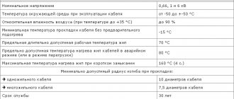
| Technical and operational characteristics of SIP-2 wire | |
| Operating voltage | 0.6/1 kV |
| Ambient temperature during operation | from -50°С to +50°С |
| Relative air humidity (at temperatures up to +35°C) | up to 98% |
| Minimum cable laying temperature without preheating | -20 °C |
| Limit long-term permissible operating t° of cores: | |
| SIP-1 | +80 °С |
| SIP-2 | +70 °С |
| Maximum permissible heating temperature of cable cores in emergency mode (or overload mode): | |
| SIP-1 | +80 °С |
| SIP-2 | +130 °С |
| Maximum temperature of the cores under the conditions of non-ignition of the cable during a short circuit: | |
| SIP-1 | +80 °С |
| SIP-2 | +250 °С |
| Minimum permissible bending radius when laying | 7.5 outer diameters |
| Life time | 25 years |
| Warranty life of the cable | 3 years |
Structural and electrical parameters
| Number and cross-section of cores, pcs. x sq.mm | Estimated weight, kg/km | Diameter, mm | Permissible current load, A | One-second short circuit current, kA | |
| with aluminum alloy core | with aluminum core, reinforced with steel wire | ||||
| 1x16 + 1x25 | 135,4 | 156,7 | 15,0 | 105 | 1,5 |
| 2x16 | — | — | 14,0 | 100 | 1,5 |
| 2x25 | — | — | 17,0 | 130 | 2,3 |
| 3x16 + 1x25 | 267,4 | 288,6 | 22,0 | 100 | 1,5 |
| 4x16 + 1x25 | 333,3 | 354,6 | 26,0 | 100 | 1,5 |
| 4x16 | — | — | 22,0 | 100 | 1,5 |
| 3x25 + 1x35 | 393,2 | 426,4 | 26,0 | 130 | 2,3 |
| 4x25 + 1x35 | 491,7 | 525,0 | 26,0 | 130 | 2,3 |
| 4x25 | — | — | 26,0 | 130 | 3,2 |
| 3x25 + 1x54.6 | — | — | 26,6 | 130 | 2,3 |
| 3x35 + 1x50 | 528,7 | 571,8 | 30 | 160 | 3,2 |
| 3x35 + 1x54.6 | — | — | 28,4 | 160 | 3,2 |
| 3x50 + 1x50 | 687,5 | 730,6 | 32 | 195 | 4,6 |
| 3x50 + 1x54.6 | — | — | 32,8 | 195 | 4,6 |
| 3x50 + 1x70 | 743,1 | 805,7 | 35,0 | 195 | 4,6 |
| 3x70 + 1x54.6 | — | — | 36 | 240 | 6,5 |
| 3x70 + 1x70 | 929,0 | 991,6 | 37,0 | 240 | 6,5 |
| 3x70 + 1x95 | 998,4 | 1085,1 | 41,0 | 240 | 6,5 |
| 3x95 + 1x70 | 1186,0 | 1248,6 | 41 | 300 | 8,8 |
| 3x95 + 1x95 | 1255,4 | 1342,1 | 45,0 | 300 | 8,8 |
| 3x120 + 1x95 | 1481,6 | 1568,3 | 47,0 | 340 | 7,2 |
Design Features:
- SIP-1A: All cores, including the supporting cable, have an insulating cover made of thermoplastic light-stabilized polyethylene.
- SIP-1: All cores, with the exception of the uninsulated zero support cable, have an insulating cover made of thermoplastic light-stabilized polyethylene.
- SIP-2A: All conductors, including the supporting cable, have an insulating cover made of cross-linked light-stabilized polyethylene.
- SIP-2: All cores, with the exception of the uninsulated zero support cable, have an insulating cover made of cross-linked light-stabilized polyethylene.
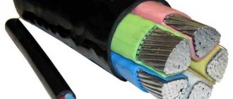
uninsulated load-bearing core (SIP-1, SIP-2)
insulated load-bearing core (SIP-1A, SIP-2A)
Technical characteristics of SIP 1,2,3,4
The design of SIP wire grades includes 4 cores, twisted with a pitch of 80-150 cm, from which they conduct electric current from 1 to 4. They have a round shape and consist of 7 (up to 95 mm2) or 19 wires. The core material is aluminum (current conductors) and its alloys (load-bearing, conductor in SIP-3). The core insulator is made of XLPE.
Some versions of SIP wires may contain auxiliary conductors, which are used either for electrical connection of lighting devices, or as control conductors necessary for the operation of various kinds of measuring or relay electrical devices. Most often, auxiliary cores are found in the design of SIP wires with a null-core cross section of 50 mm2.
SIP brands are resistant to the adhesion of ice and snow, UV radiation, have a low level of reactive losses, do not create a short circuit when touched, their installation and maintenance are quite simple and affordable.
The difference between SIP wires 1,2,3,4 lies in the design features that are related to the functional purpose of the products. Let's talk about them in a little more detail.
Characteristics of SIP 1
Brand SIP 1 is equipped with a load-bearing aluminum neutral/neutral conductor with a steel core, which does not have an insulating layer (except for the version with the “N” index), unlike phase and auxiliary conductors (if any). The scope of application of the wire is overhead power transmission lines designed for voltages up to 1 kV.
Characteristics of SIP 2 and SIP 2A
The difference between SIP 2 and SIP 1 is the presence of a zero load-bearing core insulator, which is made of cross-linked polyethylene.
The scope of application of the wire is power lines up to 1 kV, located in climate zones with active atmospheric influences. Some factories produce the SIP 2 brand without insulation of the null core, while in the SIP 2A version it is equipped with an insulating layer of XLPE.
Characteristics of SIP 3
Grade SIP 3 is made in the form of a single-core product with an insulated light-stabilized cross-linked polyethylene multi-wire conductor made of aluminum alloy.
The scope of application of the wire is overhead lines designed for an electrical voltage of 10-35 kV.
Characteristics of SIP 4
Unlike SIP 2, brand SIP 4 is not equipped with a load-bearing null core. Therefore, the scope of application of the wire is limited to the creation of branches from power transmission line supports to private houses and other consumers of electric current with voltages up to 1 kV.
Characteristics of SIP 5
The difference between SIP wires of classes 4 and 5 is in the insulator material.
In the SIP 5 brand it is made of light-stabilized cross-linked, and in SIP 4 it is made of thermoplastic polyethylene XLPE. The remaining technical characteristics and scope of application of these wires are identical.
Everything about electrics is on our website
Mega-construction begins. Installation of ASU and dispute with builders
a mystery for professional electricians inside.
Comparing micro-levels for an electrician: STABILA Pocket Electric 17775 vs Stanley 0-42-130
Micro levels for an electrician – what to choose? Is it worth overpaying for the brand? Mini level functionality. Read my micro review.
Wiring in a wooden house
Using the example of a small bathhouse in Borisovsky. The material for sofa experts has arrived, trolls, I have poured you some fresh food - today we are discussing wiring in a wooden house, frame, log house, laminated veneer lumber, inside wooden structures - in general, everything that burns very well. Expectation and reality.
Super ladder Svelt Scalissima Plus 12+12
The best purchase over the past year, one might say my hope and support, like the great mighty Russian language. You can find out what is good about the stairs of Italian manufacturers in the article.
Calculation example
An example of calculating the cross-section of a SIP cable for connecting an object with a total power of electrical appliances of 72 W, at a distance from the main power line of 340 m. Supports for hanging the SIP cable should be placed at intervals of no more than 50 m, this will significantly reduce the mechanical load on the wires. The maximum current for a three-phase circuit should be calculated when all electrical appliances are turned on. Provided that the load is distributed evenly between the phases, one phase will have:
72 kW / 3 = 24 kW.
The maximum current in one phase, taking into account the inductive and capacitive load of electrical appliances (cos fi = 0.95) will be:
24 kW / (230V* 0.95) = 110A.
According to the table, a SIP cable with a cross-section of 25 A is selected, however, given the cable length of 340 m, voltage losses must be taken into account, which should be no more than 5%. For ease of calculation, the cable length is rounded to 350 m:
- in SIP, the resistivity of aluminum is 0.0000000287 ohm/m;
- The wire resistance will be Rpr. = (0.0000000287 / 0.000025) Ohm/m * 350 m = 0.4 Ohm;
- load resistance for 24 kW. Rн = U 2 * cos fi: P = 230 2 * 0.95 / 24 kW = 2.094 Ohm;
- total resistance – Rtotal. = 0.40 Ohm. + 2.094 Ohm. = 2.5 Ohm.
Based on the calculated data, the maximum current in the phase conductor will be:
I = U / R = 230V : 2.5 Ohm = 92 A
The voltage drop is equal to I max * Rpr. = 93A * 0.4 Ohm = 37V.
37 Volts is 16 percent of the mains voltage U = 230V, which is more than the permissible 5%. According to calculations, a SIP with a cross-section of 95 sq./mm is suitable. The losses with such a wire are 11 V, which is 4.7%. When calculating a single-phase line, the total power is not divided by 3, the cable length is multiplied by 2.
Calculation method (update from 02/19/2018)
We take plate 10 and from it we find that one core is 16 sq. mm. withstands - 100 amperes. Next, we take the following calculation formulas:
for single-phase load 220V P=U*I
for three-phase load 380V P=(I1+I2+I3)3*cos φ*1.732*0.38
update from 02/19/2018 Regarding the calculation of power for a three-phase load, you need to understand that a lot depends on the type of consumers (more precisely, what kind of load they provide active or reactive, it depends on what cos φ should be substituted into the formula, in this case for calculations it is equal to 0.95 )
Dear visitors to the site, I might not have noticed your caustic but technically correct comments on the article if just today a person called me with the question: “what kind of sip do I need for 120 kW?” According to the sign, a SIP with a cross section of 50 mm square would be perfect for him. Even if we omit the fact that the length of the line affects the voltage drop (it has 150 meters), we should not forget that the load on the phases can vary, as can be seen from the formula - it takes the average value for three phases. Here you just need to understand that the phase current can exceed the maximum permissible values for a given wire cross-section.
Therefore, if the value of the load you need is closer than 10% to the table, you should choose a larger section of the vulture from the list. Let me explain with the example of 120 kW. According to the table, for this three-phase load, a SIP with a conductor cross-section of 50 mm is suitable, but this is less than 10%. That is, 121 kW * 0.9 = 109 kW. Accordingly, you need to choose SIP 3x70+1x54.6.
At the beginning of the topic, the question was raised: “will a 4x16 15kW sip handle it?” Therefore, for a private house we multiply 220Vx100A = 22 kW per phase. But don’t forget that we have three phases. And this is already 66 kilowatts in total for a residential building. Which is a 4-fold margin relative to the issued technical conditions.
“>
Advantages and disadvantages
The advantages of the products include the following characteristics: 1. There is no need to install powerful insulators on the line. 2. Security. Thanks to the insulation, there is no danger for specialists when servicing or installing self-supporting SIP wires. 3. Since the cores are connected by the same insulation, the width of the route is reduced. 4. Products can be used for regions with any weather conditions. 5. Eco-friendly. SIP cables do not affect people or animals. 6. Corrosion resistance. 7. Easy and simple installation of SIP wire. 8. Savings. To maintain and repair a line with exposed aluminum wires, you need to spend a lot of money, several times more than what is required for lines with SIP wires. Of course, there are also disadvantages, which include the large weight of wires of this type. Because of this, there is a need to more often install supports for installing the SIP cable to the house. If the products are used for installation in industrial enterprises, it will be necessary to perform reinforced insulation.
