Arduino LED strip
The LED lighting market is booming, and it's not hard to see why. They're cheap to produce, use significantly less energy than other lighting options, and don't get hot in most cases, making them safe for a wide variety of uses. One of the most popular LED products is LED strip. In this article, we'll look at how to set up the two most common types of LED strips on Arduino. These projects are very easy and even if you are new to Arduino or DIY electronics, you can do it. We will also use the Arduino IDE to control them. This project uses an Arduino Uno, although you can use almost any compatible board (such as a NodeMCU). Here are links to all the devices and materials described in the article. By clicking on the links below you can buy yourself LED strips and Arduino at a partner price. Arduino at the best price with an additional discount from Lightru SPI LED strip - excellent quality - at a partner price
The principle of load control via Arduino
The Arduino board has two types of output ports: digital and analog (PWM controller). A digital port has two possible states: logical zero and logical one. If you connect an LED to it, it will either glow or not.
The analog output is a PWM controller, to which a signal with a frequency of about 500 Hz is supplied with an adjustable duty cycle. What a PWM controller is and the principle of its operation can be found on the Internet. Through the analog port it is possible not only to turn the load on and off, but also to change the voltage (current) on it.
Command Syntax
Digital output:
pinMode(12, OUTPUT); — set port 12 to be the data output port; digitalWrite(12, HIGH); — we apply a logical one to discrete output 12, lighting the LED.
Analog output:
analogOutPin = 3; – set port 3 to output an analog value; analogWrite(3, value); – we generate a signal at the output with a voltage from 0 to 5V. The value is the duty cycle of the signal from 0 to 255. At a value of 255, the maximum voltage.
Ways to control LEDs via Arduino
Only a weak LED can be connected directly through the port, and even then it is better through a limiting resistor. Trying to connect a more powerful load will damage it.
For more powerful loads, including LED strips, an electronic switch – a transistor – is used.
Why NeoPixel?
The ability to individually control each LED in an addressable LED strip gives you the ability to create unique visual effects for your projects. But remember that if you require very high LED switching speeds, then using such an addressable LED strip is not advisable. Another advantage of the NeoPixel addressable LED strip is its low price compared to other types of addressable LEDs. NeoPixel LEDs are available in ring, strip, rectangle and round shapes - you can choose any type for your projects.
Note : The more NeoPixel LEDs you use, the more RAM and power required to drive them, and the processing time will also increase, so choose the optimal number of NeoPixel LEDs based on the capabilities of the microcontroller you are using.
Types of transistor switches
- Bipolar;
- Field;
- Composite (Darlington assembly).
| Load connection methods | ||
| Via bipolar transistor | Via field effect transistor | Via voltage switch |
When a high logic level (digitalWrite(12, HIGH);) through the output port to the base of the transistor, a reference voltage will flow to the load through the collector-emitter circuit. This way you can turn the LED on and off.
A field-effect transistor works in a similar way, but since instead of a “base” it has a drain, which is controlled not by current, but by voltage, a limiting resistor in this circuit is not necessary.
The bipolar view does not allow you to regulate powerful loads. The current through it is limited to 0.1-0.3A.
Field-effect transistors operate with more powerful loads with currents up to 2A. For an even more powerful load, Mosfet field-effect transistors are used with a current of up to 9A and a voltage of up to 60V.
Instead of field ones, you can use a Darlington assembly of bipolar transistors on ULN2003, ULN2803 microcircuits.
ULN2003 chip and circuit diagram of an electronic voltage switch:
Specifications
The addressable LED strip consists of RGB LEDs in a 5050 SMD package and PWM driver microchips. Currently, the most popular are addressable LED strips using WS2811 and WS2812B chips. The WS2811 modification is an integrated circuit (IC) in a DIP-8 (9.2x6.4 mm) or SOP-8 (5.1x4.0 mm) package. This 3-channel driver has the following pin configuration:
- 1 – PWM-regulated output (red);
- 2 – PWM-regulated output (green);
- 3 – PWM-regulated output (blue);
- 4 – general;
- 5 – data transmission output;
- 6 – data input;
- 7 – selection of operating mode;
- 8 – +5V power supply.
Addressable LED strip - each LED receives power from a common source, but is turned on by an individual command.
In an address strip using the WS2811 chip and a 5-volt power supply, the driver chip is located in close proximity to each SMD 5050 RGB LED, next to which there are also current-limiting resistors and a capacitor that protects against interference. But today such models are outdated and extremely rare. Today, addressable LED strips on WS2811 chips are available for sale only with power supply from +12 V. In this case, the WS2811 chip controls not one LED, but a group of 3 pieces.
Various shades of LED strip.
No sooner had the WS2811 IC gained popularity than the more advanced WS2812B took its place. This type of PWM driver is much more compact and is placed directly in the SMD 5050 LED housing. If you look closely, under the transparent phosphor you can see a miniature black rectangle with outgoing gold-plated conductors.
This unification has made it possible to significantly simplify the assembly of addressable LED strips and modules, and the WS2812B itself has only 4 pins:
- 1 – power supply (+3.5… +5.3 V);
- 2 – data transmission output;
- 3 – general;
- 4 – data input.
The driver IC consumes no more than 1 µA, and the maximum current of one addressable LED is 60 mA. Operating temperature range: from -25 to +80°C. When choosing an addressable LED strip, an important criterion is the degree of protection from moisture and dust. For outdoor use, only models with IP65 and IP67 are suitable.
It will be interesting The principle of operation of the diode and its scope of application
Material on the topic: What is a capacitor
The principle of operation of a transistor for smooth control of an LED strip
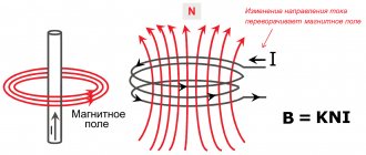
A transistor works like a water faucet, only for electrons. The higher the voltage applied to the base of the bipolar transistor or the drain of the field effect transistor, the lower the resistance in the emitter-collector circuit, the higher the current passing through the load.
Having connected the transistor to the Arduino analog port, we assign it a value from 0 to 255, and change the voltage supplied to the collector or drain from 0 to 5V. The collector-emitter circuit will pass from 0 to 100% of the load reference voltage.
To control an Arduino LED strip, you need to select a transistor of suitable power. The operating current for powering the LED meter is 300-500mA; a power bipolar transistor is suitable for these purposes. For longer lengths, a field effect transistor will be required.
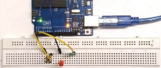
Connection diagram for LED strip to Arduino:
Connection
- The GND of the tape is connected to the GND of the microcontroller, since all signals travel relative to ground
- Any piece of tape has an input and an output: at the input the middle pin is called DI, and at the output - DO
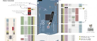
When working with Wemos, you need to specify the GPIO number in the program, not the number from the board. See pinout. It is the tape input that is connected to the Arduino, that is, the DI pin
- DI connects to any digital pin. If the strip is powered separately from the Arduino, the DI must be connected through a 100-500 Ohm resistor to avoid powering the strip through the pin, which will lead to failure of the Arduino pin or the first LED in the strip. It is better to install a resistor in any case to eliminate this possibility
- The 5V strip is connected to the power supply. Power can be shared with Arduino
- The tape consumes a lot of current, so it cannot be powered by an Arduino connected to USB. The GyverKIT kit contains a 5V network adapter; the tape must be powered from it
In the discussed circuits, the Arduino is powered by USB. For autonomous operation, you can connect power from the adapter to the 5V pin of the board.
Controlling RGB strip with Andurino
In addition to single-chip LEDs, Arduino can also work with color LEDs. By connecting the pins of each color to the analog outputs of Arduino, you can arbitrarily change the brightness of each crystal, achieving the desired color of glow.
Connection diagram for Arduino RGB LED:
The Arduino RGB strip control is constructed similarly:
It is better to assemble the Arduino RGB controller using field-effect transistors.
For smooth brightness control, you can use two buttons. One will increase the brightness of the glow, the other will decrease it.
Arduino LED strip brightness control sketch
int led = 120; set the brightness to medium level
void setup() { pinMode(4, OUTPUT); set the 4th analog port to pinMode(2, INPUT);
pinMode(4, INPUT); set the 2nd and 4th digital ports to input for polling buttons } void loop(){
button1 = digitalRead(2);
button2 = digitalRead(4); if (button1 == HIGH) pressing the first button will increase the brightness { led = led + 5;
analogWrite(4, led); } if (button2 == HIGH) pressing the second button will decrease the brightness { led = led - 5;
analogWrite(4, led); }
When you hold down the first or second button, the voltage supplied to the control contact of the electronic key smoothly changes. Then there will be a smooth change in brightness.
How to save data in Arduino nodemcu internal memory
For this task we will use several commands: EEPROM.read and EEPROM.write. We will save not only the login and password for Wi-Fi, we will save: wifi, user transition settings. To do this, we will write several functions:
- Write to EEPROM memory
- Reading from EEPROM memory
- Clearing EEPROM memory
Separately, I would like to say about cleaning, it is absolutely necessary and will need to be called every time before recording. The recording occurs byte by byte, I will call each byte a cell. We will have our own cleaning, we will not reset the bytes, we will write our own “#” symbol in each cell, this will make it easier for us and it will be more clear. I have defined three memory ranges with which we will work: from cells 20 to 90 we will store data for connecting to wifi, from 90-100 the user transition data and from 100-2000 we will store the user transitions themselves, I think this is enough for us. After that, we write the code for our functions:
//************************************************ *** void ClearEprom(int s1, int s2) { EEPROM.begin(2000); for (int i = s1; i < s2; i++) { EEPROM.write(i, 35); } EEPROM.commit(); EEPROM.end(); } //****************************************************** **** void EEPROM_writeAnything(int ee, String val) { EEPROM.begin(2000); byte *text; int len; len = val.length() + 1; unsigned char* buf = new unsigned char; val.getBytes(buf, len, 0); for (int i = 0; i < len; i++) { int s; s = ee + i; byte sim; sim = byte(buf); EEPROM.write(s, sim); } EEPROM.commit(); EEPROM.end(); } //****************************************************** **** String ReadEprom(int s, int count) { EEPROM.begin(2000); String txt; unsigned int i; for ( i = s; i < (s + count - 1); i++) { if (EEPROM.read(i) == 35) { break; } txt += char(EEPROM.read(i)); } EEPROM.commit(); EEPROM.end(); return txt; }
In the clearing function, we simply write our character with code 35 using the specified range. In the recording function, we take the value of the cell from which we are recording and the value of the row itself. In the reading function, we get the value of the byte from which we are reading and the last possible byte, but we also add an exit condition if we encounter our “zero” byte with code 35 and return a text string
Signs and symptoms of HPV 45 in women
Signs of papillomavirus type 45 in women are genital warts. They appear on the labia minora and majora, but more often in the vagina and cervix, so only a gynecologist or dermatovenerologist can detect them during an examination. Condylomas begin to cause discomfort when they increase in size and merge into large conglomerates.
Papillomavirus 45 has no characteristic symptoms, but infection can be suspected based on the following symptoms:
- foul odor from the genitals;
- pain during intercourse and orgasm;
- itching and other unpleasant sensations inside the genitals;
- painful urination;
- pain in the lower abdomen that does not go away even at rest.
When the infection caused by the human papillomavirus enters stage 3 (after which cancer develops), representatives of both sexes experience dizziness, weakness, decreased appetite, and decreased sexual activity.
Assembling the device
This is what all the necessary ingredients look like:
We solder everything according to the diagram and install it in the box:
Just in case, connecting the keys:
Key for IRF3205
Dancing lights
To safely program our board, disconnect the VIN line from the power line. You will attach it later.
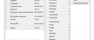
Connect your Arduino to your computer and open the Arduino IDE. Check if the correct board and port number are selected in the Tools > Board and Tools > Port menus.
We will use the FastLED library to test our setup. You can add a library by clicking on Thumbnail > Enable Library > Manage Libraries and Search FastLED. Click Install and the library will be added to the IDE.
Under File > Examples > FastLED, select DemoReel100 thumbnail. This sketch cycles through the different things you can do with the WS2812 LED strips, and it's incredibly easy to install.
All you need to change is the DATA_PIN variable to match pin 13 , and the NUM_LEDS variable to determine how many LEDs are in the strip you are using. In this case I only use a small line of 10 LEDs cut from a longer strip. Use more for a bigger light show!
This is it! Upload the sketch to your board, disconnect the USB cable and turn on the 5V power. Finally, reconnect the Arduino VIN to the power line and watch the show!
If nothing happens, check the wiring and make sure you have specified the correct Arduino pin in the demo sketch.
Difference between ws2812, ws2812b, ws2811 tapes
The most common models with built-in microcircuits are labeled WS2812 or WS2812b. With external ones – WS2811.
How does the ws2812 model differ from the ws2812b? The first ones have 6 contacts (PIN) for control, and the second ones, with the letter “b”, have only four.
At 2812, the power supply for the LED and the chip are separated. In 2812b, the power supply for the integrated driver and LED is allocated to one PIN (VDD).
What are the main differences between ws2812b and ws2811?
ws2812b – works from 5v
ws2811 – 12v power supply (the latest 5v models were discontinued in 2015)
WS2812 controls clusters of one diode at a time, WS2811 controls three LEDs simultaneously.
A significant disadvantage of ws2812 diodes is that if at least one of them burns out in the chain, then all further LEDs after it immediately stop working.
DOCUMENTATION
List of library functions and methods from the .h file
// declaration GRGB(uint8_t rpin, uint8_t gpin, uint8_t bpin); // announcement with the choice of PWM generation mode (NORM_PWM / ANY_PWM) // NORM_PWM - default PWM pins (3, 5, 6, 9, 10, 11 for UNO/NANO/MINI) // ANY_PWM - any pin is made PWM pin (frequency ~150 Hz). Details in the GyverHacks library GRGB(uint8_t rpin, uint8_t gpin, uint8_t bpin, boolean pwmmode); // NORMAL / REVERSE - PWM direction // common cathode - NORMAL // common anode - REVERSE void setDirection(boolean direction); // setting the current limit: // numLeds - number of LEDs // vcc - supply voltage in millivolts // maxCur - maximum current void setMaxCurrent(uint16_t numLeds, float vcc, int maxCur); void setBrightness(byte bright); // setting brightness (0-255) void constantBrightTick(int minVolts, int vcc); // adjustment for supply voltage void gammaTick(int vcc); // adjusting the red color when the supply voltage drops void setHEX(uint32_t color); // setting the color in HEX format (type 0x808080) void setRGB(uint8_t r, uint8_t g, uint8_t b); // set the color in RGB space (each color 0-255) void setHSV(uint8_t h, uint8_t s, uint8_t v); // set the color in HSV space (each value 0-255) void setHSV_fast(uint8_t h, uint8_t s, uint8_t v); // faster, but less beautiful version of the previous function void setKelvin(int16_t temperature); // set color as temperature in Kelvin (from 1000 to 10'000 - from red to blue) void colorWheel(int color); // set color (0 - 1530). The widest possible palette of bright colors (RGB mixtures) // smoothly change the current color to a new one in fadeTime in milliseconds // for HEX colors void fadeTo(uint32_t newColor, uint16_t fadeTime); // for RGB void fadeTo(uint8_t new_r, uint8_t new_g, uint8_t new_b, uint16_t fadeTime);
Connecting to Arduino
Direct connection of the LED strip to Arduino is only appropriate when using weak LED diodes. For an LED strip, additional electrical elements must be installed between it and the board.
Via relay
Connect the relay to the Arduino board via digital output. The controlled strip can have one of two states - on or off. If you need to organize control of an RGB strip, you will need three relays.
The current controlled by this device is limited by the power of the coil. If the power is too low, the element will not be able to close large contacts. For the highest powers, use relay assemblies.
Using a bipolar transistor
If you need to increase the current or voltage at the output, connect a bipolar transistor. When choosing it, focus on the load current. The control current does not exceed 20 mA, so add a 1 - 10 kOhm resistor to limit the current through resistance.
Using a field effect transistor
Instead of bipolar transistors, use field-effect transistors (abbreviated as MOS) to control LED strips. The difference between them is related to the control principle: bipolar ones change the current, field ones change the gate voltage. Thanks to this, a small gate current drives a large load (tens of amperes).
Using expansion cards
If you don’t want to use relays and transistors, you can buy entire blocks - expansion boards. These include Wi-Fi, Bluetooth, equalizer, driver, etc., which are required to control loads of different powers and voltages. These can be either single-channel elements, which are suitable for monochrome tapes, or multi-channel (for controlling RGB color tapes).