Purpose and scope
UZM-51M (multifunctional protective device) is used to protect electrical equipment from voltage surges in single-phase electrical networks of any premises.
This device turns off consumption sources when the supply voltage increases or decreases, and also dampens its pulsed high-voltage surges. The reasons for these deviations may be different:
- overload of transformer substations;
- turning on powerful asynchronous motors and welding machines;
- short circuit or break of the neutral wire;
- lightning striking a power line.
UZM-51M is usually used in household electrical networks, installed after the electric meter and circuit breaker at the power supply input to the room. It can also be used in three-phase networks.
Important. For complete comprehensive protection, UZM-51M is installed together with other residual current devices.
Two-phase network
Connecting the device to a two-phase network is carried out using several methods.
It is recommended to use a converter with a single adapter. A beam transceiver is selected for connection. Filters are mounted behind the trigger. To stabilize the voltage, a dinistor with a low voltage is needed. The output voltage in the circuit should be no more than 230 V.
Tip #2: Immediately before making the connection, you need to check the resistance, which should not be more than 35 Ohms. In case of sudden voltage drops, broadband dinistors should be installed. With a double converter circuit, the installation of a controller is additionally required.
Principle of operation
Using the regulators installed on the device body, you can set the relay operation limit for the upper voltage from 240 V to 290 V and for the lower voltage from 210 V to 100 V.
When connected to the power supply, the indication on the UZM-51M does not work within the first 5 s. A flashing green light indicates that voltage testing is in progress. If it corresponds to the specified parameters, the electromagnetic relay turns on, and this is indicated by the uniform illumination of the yellow and green LEDs.
Reference. You can speed up the startup of the protective device by pressing the “Test” button.
In normal operation, the UZM-51M controller constantly monitors the voltage level, and the varistor dampens its pulses to an acceptable value.
Where to install UZM
As we said earlier, a voltage relay can be installed at the entrance to an apartment or house, or at all or some groups of consumers. Sometimes it can be difficult to choose a place to install the UZM. What can be said for sure is that it is placed after the introductory machine and, most often, after the electric meter. In principle, it can be installed before the meter, but only if the operating organization agrees. And they rarely give consent to this. Therefore, usually, the UZM is placed after the meter.
Two scheme options with UZM
The power supply circuit may also contain a fire protection RCD. So where should you put the surge protection device? Before the fire protection RCD or after? If you put it in front, then when the power is turned off it will be out of action. And if after, it may be damaged as a result of jumps. In general, decisions here are made individually. We can definitely say that the voltage relay must be installed before the first branch to consumers.
Connection in three-phase networks
There are special models of protective modules for three-phase networks - UZM-3-63. All three phases are connected to this device at once, and further supplied from the output. When triggered, all phases are switched off simultaneously, so that the power is lost completely. This is not always convenient, since problems usually arise with one of the phases.
Connecting a three-phase UZM
The issue can be resolved by installing one UZM for each phase. Then, if there is a imbalance at some phase, the rest will be in operation. It's more convenient. But this connection method - three single-phase UZMs - is not suitable if there is a three-phase load. In this case, when installing three separate UZMs, when disconnected in one of the phases, there may be a “flow” through the load to the adjacent one. So the choice is yours.
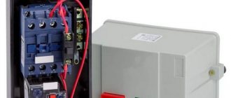
Appearance and design
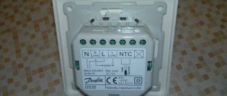
UZM-51M, like other modular devices, is mounted on a standard DIN rail. The relay housing is plastic, with two upper and two lower tunnel-type terminals.
On the front of the panel there are two rotating regulators that set the maximum and minimum voltage limits for the relay to operate, two transparent eyes and a “Test” button between them.
The lower eye glowing red means the emergency mode is turned on. The green glow shows that everything is normal. If the top eye glows yellow, it means that the electromagnetic relay contacts are closed.
The test button not only turns the device on and off, but also sets the restart time.
Inside the case there is an electromagnetic relay, a microcontroller and a varistor. The relay contacts break the phase wire, and the neutral wire passes directly through the housing as a bus.
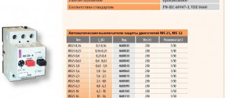
Review of manufacturers
| Manufacturer | Peculiarities | Approximate price, rub. |
| Meander | UHL4, load 63A, 2 modules | 2530 |
| LLC "Relay and Automation" | Mains voltage range 160-280 V | 2000 |
| LLC "Avtomatika-plus" | UHL4, load 63A, 2 modules | 2540 |
| Electroclub Novokuybyshevsk | Mains voltage range 209-233 V | 2800 |
Main technical characteristics and dimensions
- UZM-51M operates at a rated voltage of 220 V with a frequency of 50 Hz;
- maximum voltage - 440V with a frequency of 50 Hz;
- rated current - 63 A;
- maximum current - 80A;
- rated load power - 15.7 kW;
- maximum power - 20 kW;
- maximum absorption energy - 200 J;
- when the voltage increases, the shutdown threshold can be changed from 240 V to 290 V;
- when the voltage decreases, you can change from 100 V to 210 V;
- deviation of threshold values is no more than 3%;
- pulse protection is triggered in less than 25 ns;
- it is possible to switch the restart time from 10 s to 6 min;
- operating temperature from -25°С to +55°С;
- overall dimensions - 83x35x67 mm;
- weight - 140 g;
- service life of at least 10 years.
Analogs
Analogues of the UZM-51 device include the following devices:
- OM-63 from ;
- RN-106 from NovaTek.
RN-106 is a voltage relay that protects against unauthorized entry into an apartment with a voltage of 380 V. Too high a voltage leads to the failure of all household appliances connected to the network at that moment.
Voltage relay RN-106 prevents failure of home appliances
The OM-63 power limiter is used primarily in single-phase networks. The device immediately turns off the power supply to the home when the power consumption exceeds the established threshold. The device also protects electrical equipment connected to the network from the negative effects of significant voltage drops from nearby lightning strikes or the inclusion of overly powerful equipment.
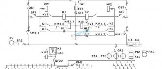
Connection diagrams
Figure 1 shows a typical connection diagram for UZM-51M.
In Fig. Figure 2 shows a diagram that allows the neutral wire to be connected on only one side, which makes it possible to combine the neutral terminals on one common terminal block.
In Fig. Figure 3 shows a diagram that allows you to disconnect the load with an additional switch.
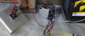
Single-phase network
The UZM is connected to a single-phase network via wired contacts. With this connection, a 200 V thyristor can be used, the filters are placed behind the plate, and the rectifier is mounted last.
For voltage stability, pulse or operational type contactors are used. The problem with magnetic oscillations is eliminated by using pass-through filters. In VO shields, filters are used with a grid winding, the converter is installed with three contacts. In this case, the maximum resistance should be less than 30 Ohms, the average output voltage should be 230 V.
Connection diagram of the UZM-51 device to a single-phase circuit in a private house or apartment
How to choose a voltage relay
When choosing, the first thing to consider is the power of the device, as well as the type of network to which it will connect. It is better to trust a professional, because the device has many types and varieties - from technical characteristics to design. One of the popular companies is Zubr. A reasonable price and a fairly high-quality device will be an assistant in the home.
Voltage control relay Zubr
In conclusion, it should be noted that UZM 51M must be in every home in order to be able to control the voltage. Otherwise, sudden surges may cause all household appliances to fail.
250 V switchboards
In order to protect electrical equipment, UZM-51M is often installed on a 250 V panel. The device connection diagram assumes the use of a comparator
However, it is important to note that capacitors are only used with low capacitance. In this case, wired type triggers are installed very rarely
Various types of filters are used to solve magnetic interference problems.
In this case, the trigger can be set to a digital or analog type. If we consider shields of the VO series, then it is more advisable to use varistors. These devices can only work with analog triggers. In this case, the maximum resistance is 55 Ohms
It is also important to note that the network overload averages 3.5 A. If we consider circuits with digital triggers, then dampers are used to improve current conductivity
These elements are installed behind the transceivers.
What problems exist in a home network and how to protect subscriber networks from parameter discrepancies
- exceeding the permissible voltage by more than 10%;
- reduction in network voltage (sag) by more than 10%;
- short-term sudden increase or decrease in voltage;
- alternating current frequency change;
- sparking, arcing on contacts when a powerful consumer is turned on;
- zero break, as a result - phase imbalance;
- short circuit on the line or inside the electrical appliance.
Some of these problems arise due to the fault of the user (maintaining equipment and lines in poor condition), some due to the fault of the energy supply company. Let's talk about this in more detail.
The quality of energy supply depends on a number of reasons:
- deterioration and compliance with the design load of power lines;
- technical condition (and actual availability) of transformer substations on each subscriber line;
- the functionality of the automation to maintain normal electrical network parameters;
- load distribution between phases;
- legality of connecting new subscribers (there are cases of exceeding technical specifications).
Let's give an example
Condition: three-phase input into a multi-storey building, common zero, phases “A”, “B” and “C” are evenly distributed between entrances 1, 2 and 3. For any reason (corrosion, mechanical damage, etc.) the zero breaks. At this time, entrance 1 is at maximum load (boilers, electric ovens), entrance 2 is at medium load (refrigerators, lighting), entrance 3 is at minimum load (a couple of TVs and several computers).
What will happen with each phase?
- Phase "A" - 1 entrance. The voltage will drop to a minimum value, close to zero.
- Phase “B” – 2nd entrance. With a high degree of probability, the voltage will remain within 220 V, although a floating change in potential is possible.
- Phase “C” – 3rd entrance. On a line with minimal load, the voltage approaches the value between phases, that is, about 380 V.
Since the operating current for each connected subscriber (group of subscribers) did not exceed the set value, the current protection circuit breaker will not work. Electrical appliances on line “C” (3rd entrance) will fail, or in the worst case, they will simply burn out. Often this situation leads to a fire.
As a rule, we don’t think about the fact that the electricity connection to our meter is not single-phase at all. This applies not only to holiday villages and small villages. Any subscriber network in cities, be it Moscow or a regional center in the Far East, is created according to a single principle.
You can install an individual transformer substation or a powerful stabilizer. But the cost of such equipment may exceed losses in an emergency on a 220 V line. What is the solution? Install the UZM protection device.
In terms of operation reliability and degree of protection, the devices are similar. However, the protection device is multifunctional: for example, UZM 51M, closes the circuit independently after restoring the power supply parameters. But the AFIS must be turned on manually.
Reviews
Experts characterize UZM-51M as a reliable, interference-resistant and durable device. It conducts electricity well and is capable of working with pulse capacitors. Resistors have a long service life; UZMs are often installed on VO switchboards. In addition, setting up basic parameters is extremely simple.
A zener diode can be installed together with the device; when installing it, you should check the compliance of the load parameters on the elements. Disadvantages of the product include large size, 220 V fuse, and inability to replace the converter.
Return to content