Electromagnets
One day, once again, leafing through a book that I found near a trash can, I noticed a simple, approximate calculation of electromagnets. The title page of the book is shown in photo 1.
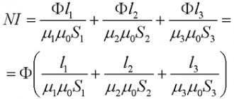
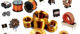
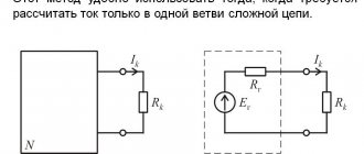
In general, their calculation is a complex process, but for radio amateurs, the calculation given in this book is quite suitable. Electromagnets are used in many electrical devices. It is a coil of wire wound on an iron core, the shape of which can be different. The iron core is one part of the magnetic circuit, and the other part, with the help of which the path of the magnetic lines of force is closed, is the armature. The magnetic circuit is characterized by the magnitude of magnetic induction - B, which depends on the field strength and magnetic permeability of the material. That is why the cores of electromagnets are made of iron, which has high magnetic permeability. In turn, the power flux, denoted in formulas by the letter F, depends on the magnetic induction. F = B • S - magnetic induction - B multiplied by the cross-sectional area of the magnetic circuit - S. The power flow also depends on the so-called magnetomotive force (Em), which is determined by the number of ampere turns per 1 cm of the path length of the power lines and can be expressed by the formula: Ф = magnetomotive force (Em) • magnetic resistance (Rm) Here Em = 1.3•I•N, where N is the number of turns of the coil, and I is the force current flowing through the coil in amperes. Another component: Rm = L/M•S, where L is the average path length of the magnetic power lines, M is the magnetic permeability, and S is the cross-section of the magnetic circuit. When designing electromagnets, it is highly desirable to obtain a large power flux. This can be achieved by reducing the magnetic resistance. To do this, you need to select a magnetic core with the shortest path length of the power lines and the largest cross-section, and the material should be an iron material with high magnetic permeability. Another way of increasing the power flow by increasing the ampere turns is not acceptable, since in order to save wire and power, one should strive to reduce the ampere turns. Usually, calculations of electromagnets are made according to special schedules. To simplify the calculations, we will also use some conclusions from the graphs. Suppose you need to determine the ampere turns and power flux of a closed iron magnetic circuit, shown in Figure 1a and made of the lowest quality iron.
Looking at the graph (unfortunately, I didn’t find it in the appendix) of the magnetization of iron, it is easy to see that the most advantageous magnetic induction is in the range from 10,000 to 14,000 lines of force per 1 cm2, which corresponds to from 2 to 7 ampere turns per 1 cm. For winding coils with the smallest number of turns and more economical in terms of power supply, for calculations it is necessary to take exactly this value (10,000 power lines per 1 cm2 at 2 ampere turns per 1 cm of length). In this case, the calculation can be made as follows. So, with the length of the magnetic circuit L = L1 + L2 equal to 20 cm + 10 cm = 30 cm, 2 × 30 = 60 ampere turns will be required. If we take the diameter D of the core (Fig. 1, c) equal to 2 cm, then its area will be equal to: S = 3.14xD2/4 = 3.14 cm2. Here the excited magnetic flux will be equal to: Ф = B x S = 10000 x 3.14 = 31400 lines of force. The lifting force of the electromagnet (P) can also be approximately calculated. P = B2 • S/25 • 1000000 = 12.4 kg. For a two-pole magnet this result should be doubled. Therefore, P = 24.8 kg = 25 kg. When determining the lifting force, it must be remembered that it depends not only on the length of the magnetic circuit, but also on the area of contact between the armature and the core. Therefore, the armature must fit exactly against the pole pieces, otherwise even the slightest air gaps will cause a strong reduction in lift. Next, the electromagnet coil is calculated. In our example, a lifting force of 25 kg is provided by 60 ampere turns. Let us consider by what means the product N•J = 60 ampere turns can be obtained. Obviously, this can be achieved either by using a high current with a small number of coil turns, for example 2 A and 30 turns, or by increasing the number of coil turns while reducing the current, for example 0.25 A and 240 turns. Thus, in order for the electromagnet to have a lifting force of 25 kg, 30 turns and 240 turns can be wound on its core, but at the same time change the value of the supply current. Of course, you can choose a different ratio. However, changing the current value within large limits is not always possible, since it will necessarily require changing the diameter of the wire used. Thus, during short-term operation (several minutes) for wires with a diameter of up to 1 mm, the permissible current density, at which the wire does not overheat, can be taken equal to 5 a/mm2. In our example, the wire should have the following cross-section: for a current of 2 a - 0.4 mm2, and for a current of 0.25 a - 0.05 mm2, the wire diameter will be 0.7 mm or 0.2 mm, respectively. Which of these wires should be wound? On the one hand, the choice of wire diameter can be determined by the available assortment of wire, on the other hand, by the capabilities of the power sources, both in current and voltage. Indeed, two coils, one of which is made of thick wire of 0.7 mm and with a small number of turns - 30, and the other of which is made of wire of 0.2 mm and a number of turns of 240, will have sharply different resistance. Knowing the diameter of the wire and its length, you can easily determine the resistance. The length of the wire L is equal to the product of the total number of turns and the length of one of them (average): L = N x L1 where L1 is the length of one turn, equal to 3.14 x D. In our example, D = 2 cm, and L1 = 6, 3 cm. Therefore, for the first coil the length of the wire will be 30 x 6.3 = 190 cm, the winding resistance to direct current will be approximately equal to? 0.1 Ohm, and for the second - 240 x 6.3 = 1,512 cm, R? 8.7 Ohm. Using Ohm's law, it is easy to calculate the required voltage. So, to create a current of 2A in the windings, the required voltage is 0.2V, and for a current of 0.25A - 2.2V. This is the elementary calculation of electromagnets. When designing electromagnets, it is necessary not only to make the indicated calculations, but also to be able to choose the material for the core, its shape, and think through the manufacturing technology. Satisfactory materials for making mug cores are bar iron (round and strip) and various. iron products: bolts, wire, nails, screws, etc. To avoid large losses on Foucault currents, cores for alternating current devices must be assembled from thin sheets of iron or wire isolated from each other. To make iron “soft,” it must be annealed. The correct choice of core shape is also of great importance. The most rational of them are ring and U-shaped. Some of the common cores are shown in Figure 1.
Views:40 004
Tags: Electromagnet
General information
Paradoxically, magnetic interactions, considered weaker in physics than electrical interactions, helped man harness electricity. By the time the phenomena of electromagnetism were discovered, the available technologies, in addition to the draft power of draft animals, used the mechanical energy of wind, water and thermal energy of steam, which was converted into mechanical energy using relatively simple methods and mechanisms.
From left to right: Michael Faraday, Joseph Henry, Andre-Marie Ampère and Hans Christian Ørsted. Source: Wikipedia
Electromechanical devices and electrical machines, based on the discovery by M. Faraday and J. Henry of the phenomena of electromagnetic induction and self-induction, made it possible to solve the problem of converting mechanical energy into electrical energy and vice versa using simple technical techniques. At the same time, the conversion of one type of energy into another occurred with a high efficiency. The application of the phenomena of electromagnetism served as the impetus for another technological leap, and humanity stepped from the age of steam, as the 19th century is conventionally called, into the 20th century of electricity.
High-voltage electric motors at a pumping station
The technical means of new technologies are electric machines in the form of direct and alternating current generators that generate electricity due to mechanical rotational energy, and electric motors that perform the inverse task.
To convert electricity into translational motion, electromechanical devices of various types are used: electromagnets, solenoids and relays. It was the latter that became the harbingers of the information revolution, being the first switching devices with a binary state. The use of a relay as a receiver of current signals (in the telegraph) and its amplification for transmission over long distances made it possible to separate information from the physical medium (paper or parchment) and ensure its almost instantaneous transmission without the help of a courier or carrier pigeon.
Magnetomotive force. Definition
Magnetomotive force (MF) is a physical quantity that characterizes the ability of electric currents to create magnetic fluxes.
The equation for magnetomotive force, otherwise known as Hopkinson's law:
F
= Ф•
R
m
where F is the MMF acting in the magnetic circuit, F is the magnetic flux in the circuit; Rm - magnetic resistance
It is clear from the equation that it is equivalent to the equation for voltage U (or, in other words, emf) according to Ohm’s law:
U = I • R
The magnetomotive force for magnetic circuits is an analogue of the electromotive force for electric circuits; it is the cause of the occurrence of magnetic flux F.
In the International System of Units SI, magnetomotive force is measured in amperes (A), in the CGS system - in gilberts (Gb)
1 A = 1.257 GB
In electrical engineering, another unit of measurement of magnetomotive force is used - the ampere-turn, numerically equal to the SI unit (ampere).
In this case, the magnetomotive force F for a solenoid, inductor or electromagnet is calculated by the formula:
F = ϖ•I
where F is the MMF acting in the magnetic circuit, ω is the number of turns in the device coil; I is the electric current in the conductor.
Other magnetomotive force measurement quantities used in various applications and their conversions from one quantity to another can be found in the physical unit converter.
Magnetomotive force in electrical engineering
Studio tape recorder, late 80s.
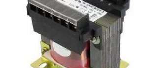
last century In the modern world there are many examples of the use of magnetomotive force, primarily in power electrical engineering. Electromagnets are widely used in electrical and electromechanical applications, including: electric motors and generators, transformers, a variety of relays, electric bells and buzzers, loudspeakers and headphones, magnetic locks, induction heaters and magnetic load grippers. This list can be supplemented with magnetic recording and data storage devices, including tape recorders, video recorders and hard drives.
Head block and hard disk read-write head
Electromagnets are used in scientific and medical equipment, being an integral part of mass spectrometers, particle accelerators, magnetic resonance imaging devices and devices for extracting foreign magnetic objects from the human body. Electromagnets are used to separate magnetic materials and objects from non-magnetic ones, as well as in electrical protection and emergency shutdown devices.
Electromagnets
Design and operating principle
An electromagnet is a device that is capable of creating a magnetic field when an electric current flows. A typical electromagnet consists of at least one winding made of conductive materials and a ferromagnetic core - a core that acquires the properties of a magnet when current flows through the winding.
The windings of electromagnets are usually made of insulated aluminum or copper wire. Although there are electromagnets with windings made of superconducting materials. The magnetic cores of electromagnets are made of soft magnetic materials - electrical or structural steel and cast iron, as well as iron-nickel or iron-cobalt alloys.
According to modern physical concepts, such materials consist of tiny magnetized regions called magnetic domains. In the absence of an external magnetic field, the domains are randomly oriented and their total magnetic field is zero. When current is supplied to the winding, a magnetic field arises, causing the domains to rearrange in the direction of this field, thereby strengthening it. When the external field for a given material reaches a certain maximum value, all domains are oriented in the direction of the field. A further increase in the flowing current does not lead to an increase in the field due to domains; this phenomenon is called magnetic saturation.
The magnetic cores of electromagnets, depending on their purpose, can have different shapes; in the simplest case, they are a set of U-shaped plates.
Working solenoid
The main advantage of electromagnets over permanent magnets is the ability to quickly regulate the force of attraction (magnetomotive force) by changing the current flowing through the winding. On the other hand, this very circumstance is a disadvantage of electromagnets compared to permanent magnets, since maintaining a magnetic field requires continuous consumption of electricity.
Because of this, electromagnets are characterized by ohmic losses due to heating of the winding wires; In addition, alternating current electromagnets are characterized by losses due to Foucault eddy currents and reorientation of magnetic domains of the core material. The latter loss is called hysteresis loss; To reduce them, electromagnet cores are made of special materials with low coercive force (low residual magnetization or, what is the same, with a small hysteresis loop area). For the same purpose, the magnetic cores of alternating current electromagnets are made in the form of a set of thin sheets with an insulating layer on the surface.
Due to the above factors, the magnetic field strength of conventional electromagnets with cores made of ferromagnetic materials is limited to 1.6 Tesla. To obtain higher values of magnetic field strength, electromagnets with windings made of superconducting materials without ferromagnetic cores are used.
Electromagnetic clutch
Electromagnetic couplings are widely used in modern technology, used for both contact and non-contact transmission of torque. When an electric current is supplied to the winding of the electromagnetic clutch, the latter, due to the created magnetic field, attracts the driven shaft reinforcement with a load and, due to friction forces, the shaft picks up speed up to the rotor rotation speed. When the current is turned off, the spring removes the shaft reinforcement from the rotor, and the shaft begins to rotate freely. This type of clutch is used in many machines and mechanisms in various fields of technology, in addition, it is widely used for production automation. A magnetic coupling is found in almost every modern car, where it is used to connect the air conditioning compressor shaft to the crankshaft of the car engine.
Electromagnetic clutch of an automobile air conditioning compressor
Electromagnetic clutches based on ferromagnetic powders have unique capabilities for transmitting torque over a wide range of forces. They can transmit torque almost linearly, allowing for very precise torque control. They are used in tension control systems for wires, foil and tapes during their production.
In addition, electromagnetic couplings have found wide application in cases where it is necessary to transmit torque through a physical non-magnetic barrier separating media with different states of matter or different aggressive properties. For example: for contactless mixing of active solutions in glass containers in chemical laboratories or for circulating water in aquariums.
Electromagnets on superconductors
Although the idea of building such electromagnets was proposed back in 1911 by the Dutch physicist Heike Kamerlingh-Ohness after the latter discovered the phenomenon of superconductivity, the first practical electromagnet from superconducting niobium wire cooled with liquid helium to a temperature of 4.2 ° K was built only in 1955. The magnetic field of this electromagnet was 0.7 Tesla.
From left to right: Heike Kamerlingh Onnes, Karl Alexander Müller and Johannes Georg Bednorz. Source: Wikipedia
The discovery of materials with high-temperature superconductivity by Swiss physicist Karl Müller and his German colleague Georg Bernodz in 1986 based on cuprates, and subsequent research in this area, made it possible to create electromagnets based on high-temperature superconductors with the temperature of boiling liquid nitrogen (–77°K or –196°C ). This circumstance has significantly reduced the cost of electromagnetic installations of this type for producing high-intensity magnetic fields.
In 2007, an electromagnet with windings made of superconducting material YBCO (yttrium-barium-copper-oxygen) created a record magnetic field of 26.8 Tesla.
Unfortunately, the superconductivity of modern superconducting materials is limited - under the influence of a very strong field or high current density, they cease to be superconductors. Nevertheless, electromagnets based on superconductors have found application not only in research technology, but also in practical medicine - they are used in installations for magnetic resonance imaging.
Bitter electromagnet
Francis Bitter
A Bitter electromagnet (or solenoid) is an electromagnet for producing super strong stationary magnetic fields. This type of electromagnet was invented by American physicist Francis Bitter in 1933 and built in 1936. It worked until 1962 and until 1958 remained the most powerful electromagnet in the world, creating a magnetic field with a magnetic induction of 10 Tesla. For a short time it could create a field of 15.2 Tesla. The problems of creating powerful electromagnets are mainly related to solving the problems of increasing the thermal stability of windings to heating by electric current, as well as increasing the mechanical strength of the structure. Structurally, it is a solenoid made of a set of copper disks, cut along the radius and isolated from each other by mica disks of the same geometry. Disks of copper and mica, alternating with each other, form a double helix. For the purpose of cooling, after the formation of the spirals, several hundred holes were drilled into them, through which cooling water was pumped. This package design made it possible to withstand enormous mechanical loads arising from the Lorentz force. The electrical power of the installation reached 2 MW.
Modern magnets of this type have changed the cut geometry of the disks and the shape of the holes (slotted holes instead of round ones), and also changed the shape and size of the plates. In addition, modern designs are made in the form of oppositely located individual sections, each of which consists of several Bitter solenoids cylindrically nested within each other.
Scientists from Radboud University in Nijmegen, the Netherlands, managed on March 31, 2014 to achieve a record value of a stationary magnetic field for this type of electromagnet of 37.5 Tesla at room temperature.
Actuating electric mechanisms
Solenoid valve
Electromagnetic drives that directly convert the energy of electric current into the translational motion of the working body are called an actuator. Structurally, they are a forward-moving electromagnet with a retracting spring-loaded armature. They are used in position control and control systems, since the control element of such a drive has two end positions corresponding to two possible positions of the electromagnet core.
Solenoid valve
A solenoid valve is an electromechanical device designed to regulate the flow of liquids and gases. Structurally, it consists of a housing, a solenoid with a movable core, on which a disk or piston is installed that regulates the flow.
Automatic circuit breaker with electromagnetic release
A valve with one outlet and one inlet opens and closes the flow. A similar valve with one inlet and two outlets switches the input flow to the corresponding output. Opening (closing) or switching of the valve occurs by applying voltage to the solenoid coil, while the magnetic core is drawn into the solenoid, which leads to the opening, closing or switching of the valve. To seal the valve, its core is placed inside a closed tube located in the solenoid.
Electromagnetic valves are used both in industrial processes and in everyday life. With their help, you can remotely control the supply of the required volume of liquid, steam or gas at the right time, which is, for example, used in irrigation systems, heating systems and other areas of technology.
Examples of the use of solenoid valves include things that are familiar to us: an automatic washing machine (filling and draining water), carburetor valves, idle air controls, transmission shifts and other car solenoid valves.
Circuit breaker release
A circuit breaker is designed to supply current to an electrical circuit during normal operation, and to break the circuit, turning off the current in the event of an abnormal value, for example, during a short circuit.
Circuit breaking is carried out by two types of releases: thermal and instantaneous current. The latter is a solenoid, the movable core of which can actuate the tripping mechanism when the current value, called the cut-off current, is exceeded. The cutoff current is usually selected within 2–10 times the rated value.
Relay
Relay
An electromagnetic relay is a device designed to close or open mechanical electrical contacts when electric current is supplied to the relay winding. Structurally, an electromagnetic relay consists of an electromagnet, a movable armature and a switch mechanically connected to the armature. The relay electromagnet is a coil with an electric wire wound around a core (armature). To enhance the magnetic flux, the relay electromagnet is equipped with an additional magnetic circuit - a yoke.
Relay
In small relays, the armature is held in its original position due to the elastic properties of mechanical contacts; in other cases, a mechanical spring is added to the relay design, which returns the armature to its original position. When electric current flows through the relay winding, the electromagnet attracts the armature, overcoming the force of the spring, and the armature, pushing the contacts, closes or opens them. The sensitivity of the relay to the control current depends on the number of turns in the winding: the higher the number of turns, the more sensitive the relay.
In some versions of the relay there may be a whole group of contacts, both normally closed and normally open in the absence of control current. Various versions of electromagnetic relays found wide application in telephony and automation devices and were used until they were replaced by semiconductor devices performing the same functions.
A separate class of relays are stepper finders - electromechanical switching devices that were used in telephony, automation and process control systems. Stepper finders are controlled by a series of current pulses and, before the advent of semiconductor relays, were widely used in various fields of technology. Particularly widespread are decade-step finders used in early designs of automatic telephone exchanges.
Telephone exchange step finders
Also a separate class of low-current relays are reed relays - devices consisting of a reed switch and an electromagnetic coil. A reed switch is a pair (or more) of ferromagnetic elastic contacts sealed in a sealed glass flask with air evacuated or filled with an inert gas. The reed switch contacts close when a magnet is approached or an electromagnet is turned on. Until recently, they were widely used as position sensors in automation devices, security alarms, computer equipment (keyboards, sensors for brushless DC motors, storage drives), and so on. Recently, reed sensors are being replaced by Hall sensors.
Reed switch
Contactors
Contactors are widely used in electrical equipment of diesel locomotives and passenger cars.
A type of electromagnetic relay is a contactor - a two-position electromagnetic device designed to remotely turn on and off power electrical circuits.
Structurally, it consists of an electromagnet, a system of contacts (both moving and non-moving) and an arc extinguishing system. In addition, the contactor design also includes auxiliary contacts for switching signaling and control circuits.
Contactors are used for switching industrial electrical circuits at voltages from several tens to several thousand volts and currents up to several thousand amperes. Their main area of application is the control of powerful electric motors in production and traction motors in transport (electric locomotives, trams, trolleybuses, elevators, etc.).