The correct selection of a voltage stabilizer must be carried out according to the main parameter - the total power of electrical appliances that need to be protected from excessive load and voltage surges connected to a specific power supply network.
Single-phase devices are most often installed to create high-quality voltage parameters in a small office or apartment. To correctly calculate the power of the stabilizer, you must first add up the power of all electrical devices. In addition to the power according to the passport of a device equipped with an electric motor, it is necessary to take into account the starting current. To do this, add about 30% power to the calculation.
The presence of a voltage stabilizer in the circuit makes it possible to protect household appliances. You can connect individual devices through the stabilizer, but it will be most effective to choose a device through which all equipment will operate
Algorithm for calculating stabilizer power
When selecting the required voltage stabilizer model, its incorrectly calculated power can lead to the following consequences:
- a stabilizer with an output power less than required will constantly turn off or not start at all, and possibly fail;
- purchasing a device with a power much higher than the required value will be a waste of money. The device will be underloaded during operation, which will reduce its efficiency.
To determine the current stabilizer power and correctly select the appropriate model, we recommend following an algorithm consisting of three steps:
- Find out the load power.
- Add the margin to the value of the power consumed by the load.
- Select a suitable stabilizer model based on the final value.
Let's look at the three points mentioned above and analyze the most common mistakes that accompany each of them.
Are you here
Home › Design engineer › 3. Electrical equipment, electrical installations › 3. Section 3.
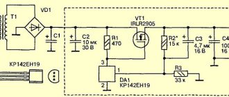
To obtain a more constant voltage across the load when the current consumed changes, a stabilizer is connected to the output of the rectifier, which can be made according to the circuit shown in Fig. 1. This device uses zener diode V5
and control transistor
V6
.
The calculation will allow you to select all elements of the stabilizer based on the specified output voltage Un
and maximum load current
In
. However, both of these parameters should not exceed the parameters of the already calculated rectifier. And if this condition is violated, then the stabilizer is first calculated, and then the rectifier and power transformer. The stabilizer is calculated in the following order.
(Uvyp) required for the stabilizer to operate.
at a given output
(Un)
:
Uvyp = Un + 3
,
Here, number 3, which characterizes the minimum voltage between the collector and emitter of the transistor, is taken based on the use of both silicon and germanium transistors. If the stabilizer is connected to a ready-made or already calculated rectifier, in further calculations it is necessary to use the real value of the rectified voltage Uvyp
.
2. Calculate the maximum power dissipated by the transistor:
Pmax = 1.3 (Uvyp - Un) In
,
3. Select a control transistor. Its maximum permissible power dissipation must be greater than the Pmax
, the maximum permissible voltage between the emitter and the collector is greater than
Uvyp
, and the maximum permissible collector current is greater than
In
.
4. Determine the maximum base current of the regulating transistor:
Ib.max = In / h21E min
,
where: h21Emin is the minimum current transfer coefficient of the selected (according to the reference book) transistor.
.
5. Select a suitable zener diode. Its stabilization voltage must be equal to the output voltage of the stabilizer, and the value of the maximum stabilization current must exceed the maximum base current Ib max
.
6. Calculate the resistance of resistor R1
:
R1 = (Uvyp - Ust) / (Ib max + Ist min)
,
Here R1 is the resistance of resistor R1, Ohm; Ust — zener diode stabilization voltage, V; Ib.max - calculated value of the maximum base current of the transistor, mA; Ist.min is the minimum stabilization current for a given zener diode, indicated in the reference book (usually 3...5 mA).
.
7. Determine the power dissipation of resistor R1
:
PR1 = (Uvyp - Ust)2 / R1
,
It may happen that a low-power zener diode is not suitable for the maximum stabilization current and you will have to choose a zener diode of significantly higher power - this happens with high consumption currents and using a transistor with a low h21E
.
In this case, it is advisable to introduce an additional low-power transistor V7
(Fig. 2), which will reduce the maximum load current for the zener diode (and therefore the stabilization current) by approximately
h21E
times and, accordingly, use a low-power zener diode.
The calculations presented here do not correct for changes in mains voltage, and also omit some other clarifications that complicate the calculations. It is easier to test the assembled stabilizer in action by changing its input voltage (or mains voltage) by ± 10% and more accurately select resistor R1 based on the greatest stability of the output voltage at maximum load current.
Find out the power connected to the load stabilizer
The load power is equal to the sum of the powers of all devices connected to the stabilizer. Before calculating the total power value, it is necessary to find out the energy consumption of each consumer. This is very simple to do: the power of electrical appliances is usually indicated in the technical documentation and is duplicated on the nameplate attached to the product.
Despite the apparent simplicity of the action, at this stage you can make several serious mistakes, which will entail choosing a stabilizer that is not suitable for your tasks.
Particular attention should be paid to equipment for which several capacities are indicated: pumps, heating, sound, climate control equipment, etc. It is important to distinguish between electrical power and the power produced by the product when performing its direct tasks, for example, thermal power for heating boilers, cooling power for air conditioners, sound power for audio systems.
Note!
When choosing a stabilizer, you should rely solely on the amount of power consumed by the load from the mains! In the passport of an electrical appliance, this parameter may be called: “power consumption”, “connecting power”, “electric power”, etc. All of the above is a reflection of one quantity - active power, which is measured in Watts (W or W).
Note!
Manufacturers of stabilizers usually build their range of stabilizers based on another quantity - total power, which is measured in Volt-Amps (VA or VA). It is important to understand that Watts and Volt-Amps are not the same thing, and therefore 1000 W is not equal to 1000 VA!
For electrical appliances that contain capacitive components or electric motors, the active and apparent power can vary significantly. Therefore, purchasing a stabilizer designed for 1000 VA with a load of 1000 W may be the wrong decision - the device will be overloaded with all the ensuing consequences.
To avoid this error, you should convert Watts to Volt-Amps and analyze not only the active, but also the total load power. Conversion from Watts to Volt-Amps is carried out by dividing the value in Watts by a special parameter - power factor or cos(φ): VA=W/cos(φ).
Cos(φ) reflects the dependence of the active power of the device on the total. The closer the cos(φ) value is to unity, the less energy is dissipated in the form of electromagnetic radiation and the more is converted into useful work.
The numerical value of cos(φ) is usually (but not always) indicated in the technical documentation of the device consuming alternating current (may be designated as “cos(φ)”, “Power Factor” or “PF”). If the manufacturer has not provided information about the power factor of its product, then for household appliances it is acceptable to take cos(φ) in the range of 0.7-0.8, except for devices that convert electricity into light and heat (incandescent lamps, electric kettles, irons, etc.). etc.), for them the range of power factor values is 0.9-1.
Modern technology, primarily computers, is often equipped with a power supply with power factor correction, which brings this parameter closer to unity - 0.95-0.99. If there is no confidence in the presence of such a function (denoted “PFC” or “KKM”), then for cos(φ) it is recommended to use the value from the typical range indicated in the previous paragraph.
The total load power should be calculated using only the power factor of the equipment corresponding to that load, and not using the input power factor of the stabilizer!
Note!
Devices that have an electric motor in their design are characterized by high starting currents. This category includes: pumps, washing machines and dishwashers, refrigerators, air conditioners, machine tools and compressors. The amount of energy consumed from the electrical network at the moment of turning on any of the above-mentioned devices can be several times higher than the value characteristic of the nominal operating mode.
Manufacturers of this equipment sometimes list the maximum power consumption directly in the characteristics of each model, and sometimes vice versa - they give only the nominal power value, trying not to draw attention to inevitable current surges. We recommend that you carefully study the documentation accompanying any equipment and look for information about the actual power consumed by the device during startup and in various operating modes. The load power is determined using the highest value given for each device!
In addition to mechanisms with electric motors, high starting currents are also typical for lighting devices. And not only with halogen and incandescent lamps, but also with the recently popular LED lamps. LEDs do not have inrush currents, but most luminaires based on them are equipped with capacitors, the inclusion of which causes a sharp increase in current consumption.
When choosing a stabilizer to protect a large lighting system, it should be taken into account that the power value that occurs when such a system is started can be many times higher than the rated value.
The principle of operation of a zener diode
Semiconductor devices exhibit nonlinear response when operating at different currents (voltages). To study functionality, use the current-voltage characteristic (CVC), which clearly demonstrates the mutual influence of the basic parameters and the features of a particular design.
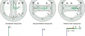
diode current-voltage characteristic
Since a zener diode is a type of diode, you can start learning how it works by looking at a typical electron-hole (np) semiconductor junction. The right side shows the diode turning on in the forward direction. It is clearly visible how, from the threshold level Up, a further increase in voltage is accompanied by an almost linear increase in the current in the circuit. Certain losses can be taken into account when drawing up an electrical circuit.
When turning the power supply back on (left side of the figure), increasing the voltage to the value shown slightly changes the current. Next (at the value of Upr) a breakdown occurs, which is determined by the characteristics of the transition:
- thermal,
- avalanche;
- tunnel
The first of the options noted in the list means an excessive increase in temperature and destruction of the semiconductor device. The third is accompanied by an increase in the current generated by paired charges. An avalanche reaction in the transition is suitable for stabilization. As shown in the graph, the voltage in this mode changes slightly.
Adding power reserve
A properly selected stabilizer should have an output power that exceeds the power required to power the load. The difference between the stabilizer power and the actual power consumption of the load is called power reserve.
The recommended margin is 30% of the load energy consumption. This value will allow:
- connect additional devices to the device during operation, the power of which was not taken into account in the initial load calculation;
- avoid overload in the event of a strong voltage drop in the electrical network.
Let us give an explanation on the second point. The fact is that the power of the stabilizer decreases when the supply voltage leaves certain limits (operating range). In particular, at 135 V in the network, instead of the declared 500 VA, the stabilizer will produce only 400 VA and, accordingly, will not be able to power the maximum load relative to its rating.
For some equipment, it is recommended to provide a power reserve of over 30%. These are, for example, air conditioners or IT equipment. In the first case, this decision is explained by an increase in the power consumed by the air conditioner during operation of the device (caused by the inevitable contamination of the filter mesh). In the second case, there is a tendency towards a constant increase in the capacity of telecommunications equipment.
Literature
- Veresov G.P.
Power supply of household radio-electronic equipment. - M.: Radio and Communications, 1983. - 128 p. - Kitaev V.V.
Power supply of communication devices. - M.: Communication, 1975. - 328 p. — 24,000 copies. - Kostikov V. G., Parfenov E. M., Shakhnov V. A.
Power sources for electronic devices. Circuit design and design: Textbook for universities. - 2. - M.: Hotline - Telecom, 2001. - 344 p. — 3000 copies. — ISBN 5-93517-052-3. - Shtilman V.I.
Microelectronic voltage stabilizers. - Kyiv: Tekhnika, 1976. - Lepaev D. A.
Electrical appliances for household use. - M.: Legprombytizdat, 1991. - 272 p. — 20,000 copies.
Selecting the stabilizer model
To determine the model that is suitable for power, it is necessary to compare the power range of stabilizers offered by the manufacturer with the energy consumption of the load - the nearest higher value in the power range will be the required power of the stabilizer.
Note!
Selecting a stabilizer with a power value that is closest to the power consumption of the load on the downside will either reduce the previously established power reserve, or in the worst case, will lead to the purchase of a stabilizer with output parameters that do not correspond to the load.
Note!
For a three-phase stabilizer, the load on each phase should be no more than 1/3 of the rated one. For example, a three-phase stabilizer with a rating of 6000 VA will power a three-phase load of 4200 VA (the power consumed from one phase will be 1400 VA), but connecting this load stabilizer to a separate phase of 2500 VA will cause an overload, since the maximum permissible value for one phase is: 6000 /3=2000 VA.
An example of selecting a stabilizer based on power
The stabilizer is purchased to simultaneously protect three single-phase consumers. We will not focus on the specific type of devices, let’s simply call them: consumer 1, consumer 2 and consumer 3.
According to factory data sheets:
- the rated power of consumer 1 is 600 W, consumer 2 – 130 W, consumer 3 – 700 W;
- The power factor of consumers 1 and 2 is 0.7, consumer 3 is 0.95.
Determine the load power. Let consumer 1 belong to the category of equipment characterized by the presence of high inrush currents. When calculating, we do not use its rated power, but the maximum starting power, equal to 1800 W according to the technical documentation. Using the above formula, we convert the power of each consumer from W to VA:
- 1800 / 0.7 = 2571.4 VA – for consumer 1;
- 130 / 0.7 = 185.7 VA – for consumer 2;
- 700 / 0.95 = 736.8 VA – for consumer 3.
Now let’s determine the total power consumption of the planned load in W and VA:
- 1800 + 130 + 700 = 2630 W;
- 2571.4 + 185.7 + 736.8 = 3493.9 VA.
We will make further selection of the stabilizer, taking into account that the total load power on the device will be 3493.9 VA, and the active one - 2630 W (note the difference in the values in W and VA).
Next, we determine the power reserve. Let us accept the recommended value of the power reserve as 30% of the load's energy consumption - to obtain the numerical value of the required reserve, we multiply the previously calculated total power of the planned load by 0.3:
- 2630 x 0.3 = 789 W – active power reserve;
- 34.939 x 0.3 = 1048.17 VA – full power reserve.
Therefore, the load power taking into account the reserve will be:
- 2630 + 789 = 3419 W;
- 3493.9 + 1048.17 = 4542.07 VA.
Now we will select single-phase stabilizer models with the required power to power our load (taking into account the reserve), using the standard power range of single-phase inverter stabilizers produced by Shtil Group of Companies:
| Apparent power, VA | Active power, W |
| 350 | 300 |
| 550 | 400 |
| 800 | 600 |
| 1000 | 800 |
| 1500 | 1125 |
| 2000 | 1500 |
| 2500 | 2000 |
| 3000 | 2500 |
| 3500 | 2750 |
| 5000 | 4500 |
| 7000 | 5500 |
| 8000 | 7200 |
| 10000 | 9000 |
| 12000 | 11000 |
| 15000 | 13500 |
| 20000 | 18000 |
The power closest to the calculated values is 5000 VA and 4500 W, therefore, this particular stabilizer is suitable for connecting consumer 1, consumer 2 and consumer 3.
Let's assume that consumer 1, consumer 2 and consumer 3 need to be connected not to a single-phase, but to a three-phase stabilizer. The standard power range of Shtil Group for such devices is as follows:
| Apparent power, VA | Active power, W |
| 6000 | 5400 |
| 10000 | 8000 |
| 15000 | 13500 |
| 20000 | 16000 |
A load with a total power of 4542.07 VA and an active power of 3419 W can be connected to one phase of a three-phase stabilizer with an output power of 15000 VA / 13500 W, in which a separate phase will produce a maximum of 5000 VA / 4500 W.
Load distribution, that is, connecting each consumer to a separate phase, will allow you to choose a less powerful stabilizer model. The greatest load will be on the phase feeding consumer 1, whose energy consumption is 1800 W / 2571.4 VA.
Let's calculate the 1 power reserve required by the consumer (let's take the recommended reserve value of 30%):
- 1800 x 0.3 = 540 W – active power reserve;
- 2571.4 x 0.3 = 771.4 VA – full power reserve;
- 1800 + 540 = 2340 W – active power of consumer 1 taking into account the reserve;
- 2571.4 + 771.4 = 3342.8 VA – total power of consumer 1 taking into account the reserve.
This means that the maximum possible load on one phase of the stabilizer, provided that three consumers are connected to different phases, can be: 3342.8 VA / 2340 W.
Let's choose a stabilizer model with an output power of 10000 VA / 8000 W, in which the permissible load per phase is approximately equal to 3333 VA / 2666 W. In this case, it is permissible to choose a stabilizer with a total power slightly less than the calculated one - in fact, this will reduce the power reserve for consumer 1 by 1-2%.
Note!
There are stabilizers with a “3 in 1” topology, that is, with a three-phase input and a single-phase output. Such a scheme allows you to evenly load a three-phase network when connecting a single-phase load.
Parametric stabilizer
An engineering program designed to calculate parametric stabilizers based on silicon or gas-discharge zener diodes used in power supplies. The calculation method was developed by the author of the program and published in the article “Moskatov E. Calculation of parametric stabilizers. - Radiomir, 2006, No. 7, p. 22 - 25".
The help for the program provides answers to typical questions and provides reference data for silicon and gas-discharge zener diodes. The license status is donationware (freeware class), that is, the program can be used freely, and payment is not required. All materials presented for downloading are in Russian.
| Download materials | Additional Information |
| In this final version of the program, additional checks for overflow of the source data were introduced. Data saving has been introduced. The program interface has become more ergonomic. All available graphics, pictograms and icons have been redesigned to remove any material created by other authors from the executable file, help file and installer. The program was created in Windows XP Home Edition using licensed software. The following programs were used: Borland C++Builder 6.0 personal (for writing part of the code and debugging the implementation of the algorithm), Borland Turbo C++ 10.0 (for compiling the executable file), Microsoft Office Visio (for drawing circuit diagrams and drawings), OpenOffice.org (for writing program help), Sea Monkey (for creating html help files using a “linker”), htm2chm (for compiling html files into a chm help file), IrfanView (for reducing the number of colors in bitmaps), Slow View ( to give the effect of a 3D button in pictures), Inno Setup (for creating an installer), FET XP Authenticode (for electronically signing files). The extension of the packed file is EXE, size is 782 KB. Known issues and features. 1. In safe mode, the menu text in Russian is not displayed correctly (with special characters); in other parts of the program the text is displayed correctly. Solution to the problem: do not use the program in safe mode or use the English version of the program, if one exists. 2. The program will work in Windows 95, but it will not be possible to view the help file using the tools built into the OS. Using a chm file viewer will solve this problem. 3. If the monitor image resolution is less than 800 × 600 pixels, then the program interface elements will be shifted on the form. Solution to the problem: do not use the program with such a low monitor resolution. | |
| Help file for the program “Parametric stabilizer 4.0.0.0”. It can be printed. File extension - PDF, size - 135 KB. | |
| Source texts of the program “Parametric stabilizer 4.0.0.0”, which can be analyzed in the Borland Developer Studio environment. File extension - ZIP, size - 134 KB. | |
| History of the main versions of the “Parametric stabilizer” program. File extension - TXT, size - 3.5 KB. |
Recommended Hardware Requirements
A computer with an Intel Pentium/Celeron family processor or a compatible processor with a clock speed of at least 200 MHz or more powerful.
RAM: 32 MB.
Free disk space: 2 MB.
Video card and monitor with a resolution of at least 800 × 600 pixels.
Keyboard, mouse or other pointing device.
Recommended system software requirements
Operating system Microsoft Windows 98 Second Edition, Microsoft Windows Millennium, Windows 2000 Professional, Windows XP Home Edition, Windows XP Professional, Windows 2003 Server, Windows Vista Starter, Windows Vista Home Basic, Windows Vista Home Premium, Windows Vista Business, Windows Vista Enterprise ,Windows Vista Ultimate.
Since the program has a Russian-language interface, the operating system must provide the necessary language support.
Screenshot of the program “Parametric stabilizer 4.0.0.0”
Let's sum it up
To avoid mistakes when determining the power of the stabilizer and wasting money on a device that will ultimately turn out to be useless, you must:
- when calculating the load power, use the value of the power consumed by the electrical appliance from the network, and not the value of the power characterizing the useful operation of this electrical appliance;
- when calculating the total load power, use the power factor corresponding to this load, and not the input power factor of the stabilizer;
- calculate the load power with mandatory consideration of starting currents for all devices characterized by their high value;
- if necessary, convert W to VA and analyze the load power in units of measurement corresponding to the units on the basis of which the power range of stabilizers is built;
- select the stabilizer power taking into account the required reserve;
- choose a stabilizer with a rated power higher than the calculated load power (only a slight rounding of the load power downwards is acceptable, provided there is a pre-established power reserve);
- choose a three-phase stabilizer for a single-phase load, analyzing not only the rated output power of the device, but also the power of an individual phase.
Carefulness in calculations and compliance with all the above rules will help you choose a stabilizer model that meets the requirements of your load. In case of any difficulties or questions, we recommend that you consult with specialists!
conclusions
So, let's summarize briefly.
- In the vast majority of cases, the network voltage is within acceptable limits and a stabilizer is not needed. And your outlet is probably fine too.
- If there is really a problem with the voltage, then we take a single-phase relay stabilizer with a power of 10-15 kW. In 90% of cases this will be enough. More accurate calculations can be made using the above method.
- If you are annoyed by loud clicking sounds and blinking lights when the stabilizer switches, then instead of a relay we buy an electromechanical one, which has smooth adjustment.