Operating and installation conditions for SIP-4 4x70:
— Type of climatic modification of wires B, placement categories 1, 2 and 3 according to GOST 15150-69; — SIP wires 4 4x70 are resistant to bending at temperatures: up to -40°C; — Laying and installation of SIP 4 4x70 wires must be carried out at an ambient temperature of: not lower than - 20°C; — Allowable forces in the zero load-bearing core during tension and operation should not exceed: 45 N/mm2; — SIP 4 4x70 wires after exposure to water at a temperature of (20+10) °C for at least 10 minutes must withstand an alternating voltage test at a frequency of 50 Hz for at least 5 minutes at the construction length: • self-supporting insulated with cross-linked polyethylene - 4 kV ; • self-supporting insulated with thermoplastic polyethylene and flame retardant polyethylene composition – 2.5 kV; — Operation of SIP 4 4x70 wires at temperatures from - 60°C to + 50°C.
Main SIP
Characteristic
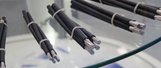
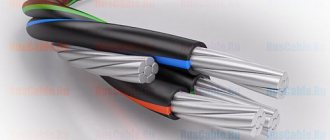
Trunk SIPs consist of four insulated wires twisted during manufacture: one for each of the three phases and one neutral carrier. The twist of the cores is in the right direction. Often one or two insulated aluminum wires are added to the bundle for lighting public places (with a cross-section of 16 or 25 mm2).
Carrier neutral wire
lived
- round, twisted from aluminum alloy ABE, with a diameter of 70 or 54.6 mm2;
insulation
- light-stabilized silanol cross-linked polyethylene, extruded black.
Characteristics of 54.6 mm2 carrier wire
- nominal cross-section - 54.6 mm2 (7 wires of 3.15 mm each);
- core diameter - 9.2 mm;
- insulation diameter - min. 12.4 mm, max. 12.8 mm; min.
- tensile strength - 16.6 kN;
- modulus of elasticity - 62000 MPa.
Characteristics of 70 mm2 carrier wire
- nominal cross-section - 70 mm2 (7 wires of 3.45 mm each);
- core diameter - 9.7 mm;
- insulation diameter - min. 13.0 mm, max. 13.2 mm;
- min. tensile strength - 20.5 kN;
- modulus of elasticity - 62000 MPa;
- linear expansion coefficient - 23x10x6;
- linear resistance - 0.500 Ohm/km
Technical characteristics of main SIPs
| No. | SIP 2A Core cross-sectional area, mm2 | Diameter (minimum), mm | Harness weight, kg/km | Linear resistance at 20°C, Ohm/km | Current strength in operating mode, A | ||||||
| veins | insulated cores | tourniquet | |||||||||
| phase wire | lighting wire | phase wire | lighting wire | phase wire | lighting wire | phase wire | lighting wire | ||||
| 1 | 3x25+54.6 | 5,9 | — | 8,7 | — | 24 | 531 | 1,200 | — | 112 | — |
| 2 | 3x25+54.6+16 | 5,9 | 4,85 | 8,7 | 7,45 | 25 | 600 | 1,200 | 1,910 | 112 | 83 |
| 3 | 3x25+54.6+2x16 | 5,9 | 4,85 | 8,7 | 7,45 | 26,5 | 670 | 1,200 | 1,910 | 112 | 83 |
| 4 | 3x35+54.6 | 6,9 | — | 10,1 | — | 24,6 | 641 | 0,868 | — | 138 | — |
| 5 | 3x35+54.6+16 | 6,9 | 4,85 | 10,1 | 7,45 | 25,5 | 710 | 0,641 | 1,910 | 138 | 83 |
| 6 | 3x35+54.6+2x16 | 6,9 | 4,85 | 10,1 | 7,45 | 27,5 | 779 | 0,641 | 1,910 | 138 | 83 |
| 7 | 3x50+54.6 | 8,1 | — | 11,3 | — | 27 | 770 | 0,641 | — | 165 | — |
| 8 | 3x50+54.6+16 | 8,1 | 4,85 | 11,3 | 7,45 | 28,5 | 839 | 0,443 | 1,910 | 165 | 83 |
| 9 | 3x50+54.6+2x16 | 8,1 | 4,85 | 11,3 | 7,45 | 30 | 907 | 0,443 | 1,910 | 165 | 83 |
| 10 | 3x70+54.6 | 9,7 | — | 13,3 | — | 30 | 985 | 0,443 | — | 180 | — |
| 11 | 3x70+54.6+16 | 9,7 | 4,85 | 13,3 | 7,45 | 32,2 | 1054 | 0,443 | 1,910 | 180 | 83 |
| 12 | 3x70+54.6+2x16 | 9,7 | 4,85 | 13,3 | 7,45 | 33 | 1122 | 0,443 | 1,910 | 180 | 83 |
| 13 | 3x70+70 | 9,7 | — | 13,3 | — | 32 | 1034 | 0,443 | — | 180 | — |
| 14 | 3x70+70+16 | 9,7 | 4,85 | 13,3 | 7,45 | 33 | 1103 | 0,443 | 1,910 | 180 | 83 |
| 15 | 3x70+70+2x16 | 9,7 | 4,85 | 13,3 | 7,45 | 34 | 1172 | 0,443 | 1,910 | 180 | 83 |
| 16 | 3х95+70 | 11,5 | — | 13,3 | — | 35 | 1130 | 0,320 | — | 258 | — |
| 17 | 3x95+70+16 | 11,5 | 4,85 | 13,3 | 7,45 | 36 | 1200 | 0,320 | 1,910 | 258 | 83 |
| 18 | 3x95+70+2x16 | 11,5 | 4,85 | 13,3 | 7,45 | 37 | 1265 | 0,320 | 1,910 | 258 | 83 |
| 19 | 3x120+70 | 12,8 | — | 16,4 | — | 37 | 1380 | 0,253 | — | 300 | — |
| 20 | 3x120+70+16 | 12,8 | 4,85 | 16,4 | 7,45 | 38 | 1450 | 0,253 | 1,910 | 300 | 83 |
| 21 | 3x120+70+2x16 | 12,8 | 4,85 | 16,4 | 7,45 | 39 | 1520 | 0,253 | 1,910 | 300 | 83 |
| 22 | 3x150+70 | 14,45 | — | 18,05 | — | 40 | 1749 | 0,206 | — | 344 | — |
| 23 | 3x150+70+16 | 14,45 | 4,85 | 18,05 | 7,45 | 41 | 1817 | 0,206 | 1,910 | 344 | 83 |
| 24 | 3x120+70+2x16 | 14,45 | 4,85 | 18,05 | 7,45 | 42 | 1885 | 0,206 | 1,910 | 344 | 83 |
Permissible current loads of insulated wires for overhead transmission lines (SIP)
| Nominal cross-section of main cores, mm2 | Permissible load current, A, no more | Permissible one-second short circuit current, kA, no more | |||
| Self-supporting insulated wires | Protected wires | Self-supporting insulated wires | Protected wires | ||
| 20kV | 35kV | ||||
| 16 | 100 | — | — | 1,5 | — |
| 25 | 130 | — | — | 2,3 | — |
| 35 | 160 | 200 | 220 | 3,2 | 3,0 |
| 50 | 195 | 245 | 270 | 4,6 | 4,3 |
| 70 | 240 | 310 | 340 | 6,5 | 6,0 |
| 95 | 300 | 370 | 400 | 8,8 | 8,2 |
| 120 | 340 | 430 | 460 | 10,9 | 10,3 |
| 150 | 380 | 485 | 520 | 13,2 | 12,9 |
| 185 | 436 | 560 | 600 | 16,5 | 15,9 |
| 240 | 515 | 600 | 670 | 22,0 | 20,6 |
Mechanical characteristics of SIP wire
| Estimated outer diameter of the wire, mm" | Estimated weight of 1 km of wire, kg | ||
| SIP-1-0.6/1 | 1×16+1×25 | 15 | 135 |
| 3×16+1×25 | 22 | 270 | |
| 3×25+1x35 | 26 | 390 | |
| 3×35+1×50 | 30 | 530 | |
| 3×50+1×50 | 32 | 685 | |
| 3×50+1×70 | 35 | 740 | |
| 3×70+1×70 | 37 | 930 | |
| 3×70+1×95 | 41 | 990 | |
| 3×95+1×70 | 41 | 1190 | |
| 3×95+1×95 | 43 | 1255 | |
| 3×120+1×95 | 46 | 1480 | |
| 3x150+1x95 | 48 | 1715 | |
| 3×185+1×95 | 52 | 2330 | |
| 3×240+1×95 | 56 | 2895 | |
| SIP-2-0.6/1 | 3×16+1×25 | 24 | 308 |
| 3×16+1×54.6 | 28 | 427 | |
| 3×25+1×35 | 27 | 424 | |
| 3x25+1x54.6 | 30 | 512 | |
| 3×35+1×50 | 31 | 571 | |
| 3×35+1×54.6 | 32 | 606 | |
| 3×50+1×50 | 34 | 727 | |
| 3×50+1×54.6 | 35 | 762 | |
| 3×50+1×70 | 36 | 798 | |
| 3×70+1×54.6 | 39 | 973 | |
| 3×70+1×70 | 40 | 1010 | |
| 3×70+1×95 | 41 | 1087 | |
| 3×95+1×70 | 43 | 1240 | |
| 3×95+1×95 | 45 | 1319 | |
| 3×120+1×95 | 48 | 1553 | |
| 3×150+1×95 | 50 | 1787 | |
| 3×185+1×95 | 55 | 2403 | |
| 3×240+1×95 | 60 | 2968 | |
| SIP-3 -20 | 1×35 | 12 | 165 |
| 1×50 | 13 | 215 | |
| 1×70 | 15 | 282 | |
| 1×95 | 16 | 364 | |
| 1×120 | 18 | 445 | |
| 1×150 | 19 | 540 | |
| 1×185 | 21 | 722 | |
| 1×240 | 24 | 950 | |
| SIP-3-35 | 1×35 | 14 | 209 |
| 1×50 | 16 | 263 | |
| 1×70 | 17 | 334 | |
| 1×95 | 19 | 421 | |
| 1×120 | 20 | 518 | |
| 1×150 | 22 | 618 | |
| 1×185 | 24 | 808 | |
| 1×240 | 26 | 1045 | |
| SIP -4 0.6/1 kV | 2x16 | 15 | 139 |
| 4x16 | 18 | 278 | |
| 2x25 | 17 | 196 | |
| 4x25 | 21 | 392 |
Selecting the cable cross-section according to power
You can select the wire cross-section according to the power of the devices that will be connected. These devices are called load and the method can also be called “by load”. Its essence does not change from this.
The choice of cable cross-section depends on the power and current
Collecting data
First, find the power consumption in the passport data of household appliances and write it down on a piece of paper. If it’s easier, you can look at nameplates - metal plates or stickers attached to the body of equipment and equipment. There is basic information and, more often than not, power. The easiest way to identify it is by its units of measurement. If a product is manufactured in Russia, Belarus, or Ukraine, it is usually designated W or kW; on equipment from Europe, Asia or America, the English designation for watts is usually W, and the power consumption (this is what is needed) is designated by the abbreviation “TOT” or TOT MAX.
Example of a nameplate with basic technical information. There is something similar on any technology
If this source is also unavailable (the information has become lost, for example, or you are just planning to purchase equipment, but have not yet decided on the model), you can take the average statistical data. For convenience, they are summarized in a table.
Table of power consumption of various electrical appliances
Find the equipment you plan to install and write down the power. Sometimes it is given with a wide spread, so sometimes it is difficult to understand which figure to take. In this case, it is better to take the maximum. As a result, when calculating, you will slightly overestimate the power of the equipment and will need a cable with a larger cross-section. But for calculating the cable cross-section it is good. Only cables with a smaller cross-section than necessary will burn. Routes with a large cross-section work for a long time, as they heat up less.
The essence of the method
To select the wire cross-section for the load, add up the power of the devices that will be connected to this conductor
It is important that all powers are expressed in the same units of measurement - either in watts (W) or in kilowatts (kW). If there are different values, we bring them to a single result
To convert, kilowatts are multiplied by 1000 to get watts. For example, let's convert 1.5 kW into watts. This will be 1.5 kW * 1000 = 1500 W.
If necessary, you can carry out the reverse conversion - convert watts to kilowatts. To do this, divide the figure in watts by 1000 to get kW. For example, 500 W / 1000 = 0.5 kW.
Next, the selection of the cable cross-section actually begins. It's very simple - we use a table.
| Cable cross-section, mm2 | Conductor diameter, mm | Copper wire | Aluminum wire | ||||
| Current, A | power, kWt | Current, A | power, kWt | ||||
| 220 V | 380 V | 220 V | 380 V | ||||
| 0.5 mm2 | 0.80 mm | 6 A | 1.3 kW | 2.3 kW | |||
| 0.75 mm2 | 0.98 mm | 10 A | 2.2 kW | 3.8 kW | |||
| 1.0 mm2 | 1.13 mm | 14 A | 3.1 kW | 5.3 kW | |||
| 1.5 mm2 | 1.38 mm | 15 A | 3.3 kW | 5.7 kW | 10 A | 2.2 kW | 3.8 kW |
| 2.0 mm2 | 1.60 mm | 19 A | 4.2 kW | 7.2 kW | 14 A | 3.1 kW | 5.3 kW |
| 2.5 mm2 | 1.78 mm | 21 A | 4.6 kW | 8.0 kW | 16 A | 3.5 kW | 6.1 kW |
| 4.0 mm2 | 2.26 mm | 27 A | 5.9 kW | 10.3 kW | 21 A | 4.6 kW | 8.0 kW |
| 6.0 mm2 | 2.76 mm | 34 A | 7.5 kW | 12.9 kW | 26 A | 5.7 kW | 9.9 kW |
| 10.0 mm2 | 3.57 mm | 50 A | 11.0 kW | 19.0 kW | 38 A | 8.4 kW | 14.4 kW |
| 16.0 mm2 | 4.51 mm | 80 A | 17.6 kW | 30.4 kW | 55 A | 12.1 kW | 20.9 kW |
| 25.0 mm2 | 5.64 mm | 100 A | 22.0 kW | 38.0 kW | 65 A | 14.3 kW | 24.7 kW |
To find the required cable cross-section in the corresponding column - 220 V or 380 V - we find a figure that is equal to or slightly greater than the power we previously calculated. We select the column based on how many phases are in your network. Single-phase - 220 V, three-phase 380 V.
In the found line, look at the value in the first column. This will be the required cable cross-section for a given load (power consumption of devices). You will need to look for a cable with cores of this cross-section.
A little about whether to use copper wire or aluminum. In most cases, when laying wiring in a house or apartment, cables with copper conductors are used. Such cables are more expensive than aluminum ones, but they are more flexible, have a smaller cross-section, and are easier to work with. But copper cables with a large cross-section are no more flexible than aluminum ones. And under heavy loads - at the entrance to a house or apartment with a large planned power (from 10 kW or more), it is more advisable to use a cable with aluminum conductors - you can save a little.
How many kilowatts can a SIP withstand?
| SIP section | voltage 380V (3-phase load) | voltage 220V (1 phase load) |
| SIP 4x16 | 62 kW | 22 kW |
| SIP 4x25 | 80 kW | 29 kW |
| SIP 4x35 | 99 kW | 35 kW |
| SIP 4x50 | 121 kW | 43 kW |
| SIP 4x70 | 149 kW | 53 kW |
| SIP 4x95 | 186 kW | 66 kW |
| SIP 4x120 | 211 kW | 75 kW |
| SIP 4x150 | 236 kW | 84 kW |
| SIP 4x185 | 270 kW | 96 kW |
| SIP 4x240 | 320 kW | 113 kW |
Comprehensive supply of cable and wire products and fittings
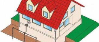
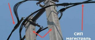
Wire SIP-4 4x70 - designed for equipment of main overhead power lines (OHL) and linear branches (to residential and non-residential buildings and engineering structures) by hanging on special overhead line supports, as well as by laying along the facades (walls) of buildings and corresponding structures.
Wire SIP-4 4x70
When installing this wire, you can do without installing support cables. Suspension with wires designed for different voltage levels, as well as with telephone cables, is allowed.
Since SIP 4 4x70 wire, along with its practicality and ease of installation, is highly resistant to aggressive environments, it can be used in fire hazardous areas, on sea coasts, the shores of salt lakes and in areas where saline sands are present, as well as in areas with high density industrial production.
The SIP-4 4x70 wire is designed for a rated voltage of 1 kV and a frequency of 50 Hz (according to the standards for electrical equipment GOST R 52373-2005).
The insulation is made of cross-linked light-stabilized polyethylene, so the price for SIP-4 4x70 is higher than for non-insulated analogues (AC wires).
Explanation of marking SIP-4 4x70:
- C – type: self-supporting;
- I – isolated;
- P – wire;
- 4 – a type of design (there is no load-bearing core, unlike the SIP-2 3x70+1x70 wire);
- 4 – number of main conductors;
- 70 – cross-sectional area of the cores (in mm2).
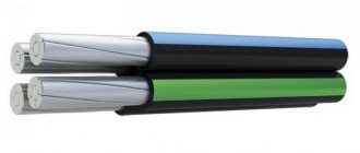
The conductors in this model have a color (usually in the form of longitudinal stripes of red, yellow, green, blue) or digital difference.
Wire design
Model SIP-4 4x70 consists of the following structural elements:
- The conductor is conductive. Made of aluminum, has a compacted multi-wire structure (minimum number of wires in one core - 7 pcs.).
- Core insulation Made from cross-linked light-stabilized polyethylene with a nominal thickness of 1.70 mm (but not less than 1.43 mm). Provides a resistance of 10 ohms.
A separate (special) carrier conductor is not provided in the SIP-4 4x70 wire.
The insulated conductors are twisted together with the direction of twist to the right, with a pitch of 45 mm.
Possible modifications:
- SIPg-4 4x70 – sealed version, resistant to longitudinal spread of water;
- SIPn-4 4x70 – does not spread combustion to other products, does not form burning fragments during its own combustion.
Technical characteristics of SIP-4 4x70:
- wire type – power;
- AC voltage (nominal) – 1000 V;
- frequency – 50 Hz;
- number of conductors – 4;
- cross-section – round, area 70 mm2;
- current load (permissible) – 240 A;
- core resistance (active, at a frequency of 50 Hz) – 0.568 Ohm/km;
- heating temperatures of the conductor (permissible) – +90° C (long-term), +130° C (overload mode), +250° C (maximum permissible, during a short circuit);
- weight of 1 km of wire (theoretical) – 978.5 kg (the actual weight of SIP-4 4x70 depends on the specific manufacturing plant);
- diameter SIPn-4 4x70 (outer) – 31.8 mm;
- permissible bending radius (minimum) – 318 mm (10 wire diameters);
- construction length – 300 m;
- temperature during installation – not lower than -20° C;
- operating temperature – from -60° C to +50° C;
- climatic version - UHL;
- placement - categories 1/2/3 (in atmosphere type II/III according to GOST 15150-69);
- warranty period – 3 years;
- service life - at least 40 years.
