The specificity of the problem of lightning protection on overhead lines (overhead lines with protected wires) is that if the wires in the insulation are not protected by anything, then during a lightning overvoltage and the insulator overlaps, an arc is formed, which simply has nowhere to move along the wire.
Accordingly, it burns at the point of insulation breakdown until the protection at the substation is triggered and the overhead line emergency shutdown. Since the protection in this case does not work immediately, the following consequences may occur:
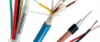
- damage to SIP-3 insulation
- destruction of the insulator itself at the VLZ
- burnout and broken wire
It is the burnout of the wire that is the main condition for the need to use lightning protection devices for SIP-3.
Arc horns
Initially, a system of arc protection “horns” was widely used. When an arc and a single-phase fault were artificially converted into a two-phase short circuit with a guaranteed shutdown of the power line.
However, this system has significant disadvantages:
- it does not protect the insulation from overvoltage
- does not prevent line disconnection, but rather contributes to it
Meanwhile, for lines with an isolated neutral, a single-phase fault is not an emergency mode requiring immediate shutdown.
In addition, the “horns” periodically burn and require replacement.
And when the overhead line passes through plantings and forest clearings, interphase short circuits are possible due to contact with branches.
Therefore, to protect overhead power lines of medium voltage 6-20 kV from lightning overvoltages, special devices began to be used - long spark gaps of the loop type RDIP.
Rolling out SIP-3 wire
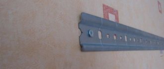
A power roller of a slightly different design with a bandage tape is attached to the initial anchor support. If the intermediate crossbars do not have loops or a hook from which the roller could be hung, then devices with bandage tape are used everywhere.
Technical characteristics and brands of mounting rollers from Ensto, Sicam, Niled, KVT:
Ensto
Sicam
Niled
KVT
Rolling out from the drum should be done in such a way as to prevent the wire from touching the ground and the support posts. A leader rope is used for this. It must be made of synthetic rope with a minimum diameter of 6mm.
A standard drum from Ensto ST204.2060-0030 easily fits 1100 m of such cable.
Basic requirements for the rope:
high mechanical breaking load
low susceptibility to stretching
UV and moisture resistance
dielectric
If the length of the cable is not sufficient, then it can be spliced together with special connecting brackets.
The ST204 motorized winch is secured to the final anchor support. A drum with a leader rope is placed on it.
The motor winch provides ease of installation and reduces the total operating time several times.
The portable sheeting machine is installed using a belt or chain banding device.
The leader cable is first pulled through the mounting roller on the final support, and then sequentially through the intermediate supports, pulling it along the grooves of the pin insulators.
The rope stretched across the entire anchor section is connected to the wire using a mounting stocking. The leader rope is simply tied with a compact knot directly to the loop of the mounting stocking. At the same time, unlike low voltage wires SIP-4, a swivel for SIP-3 does not need to be used.
The edge of the stocking is wrapped with turns of electrical tape to prevent it from slipping.
One of the installers uses the radio to give a command to the other, who controls the winch, to turn it on. He must also constantly monitor the passage of the cable-to-wire connection along the entire line. And if a wire gets stuck, immediately give the command to stop the winch.
The SIP wire must be pulled evenly, without jerking, at a speed of less than 5 km/h. When rolling out, do not allow the wire to touch the ground and support posts.
Long spark gaps
These devices must be installed along the entire length of the overhead line, at the approaches to the substation and cable inserts. This makes it possible to eliminate the overlap of insulation on the line and negate the negative consequences of induced lightning overvoltages.
This should not happen:
- emergency power line outages
- destruction of insulators
- burnt wire
- plus protection of substation equipment and cable inserts is provided
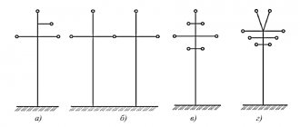
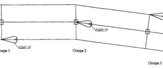
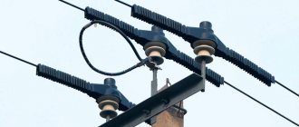
Long spark gaps RDIP or PDR-10 (from Niled) must be installed on a protected section of the route, one for each support with cyclic phase rotation.
That is:
- on support No. 1 we connect the arrester to the FA
- on support No. 2 on fV
- on support No. 3 on FS
It is not entirely advisable to place two RDIP arresters simultaneously on adjacent phases of an intermediate support with pin insulation, even if space permits. Otherwise, a single-phase circuit may turn into a two-phase circuit with subsequent emergency shutdown of the overhead line.
Characteristics
The discharge characteristics of RDIP-10 ensure that none of the insulators of all three phases in this circuit overlap, since each of them is protected by a spark gap installed electrically parallel to it and located either directly next to the insulator or on an adjacent support.
At levels of induced overvoltages close to the surge voltage of the arrester, it is possible that the arrester may close on only one support, leading to a single-phase ground fault. The short-circuit current does not exceed 10-20 A, and the loop arrester with a total overlap length of 80 cm is guaranteed to exclude the occurrence of a power arc.
Main technical characteristics
| Voltage class | 10 kV |
| Surface overlap length | 78 cm |
| External spark gap | 2-4 cm |
| Pulse 50% discharge voltage, no more on positive polarity on negative polarity | 110 kV 90 kV |
| Coordination voltage with insulator SHF10-G * | 300 kV |
| Repeated impulse voltage withstood by internal insulation, not less | 50 pulses 300 kV |
| Withstand voltage of industrial frequency, not less dry under rain | 42 kV 28 kV |
| Repeatedly withstand pulse current 8/20 µs, not less | 20 pulses 40 kA |
| Weight | 2.3 kg |
| Service life, not less | 30 years |
Installation
The arrester is designed to protect 6, 10 kV overhead lines from induced lightning overvoltages, which constitute the overwhelming share of the total number of lightning overvoltages that can lead to insulation flashovers.
It is known that the magnitude of induced overvoltages does not exceed 300 kV, and this allows, with proper organization of lightning protection, to exclude the possibility of simultaneous overlap of two or three phases on one support and, accordingly, interphase short circuits. To do this, it is necessary to install one arrester per support with alternating phases, for example, on the first support the arrester is installed on phase A, on the second - on phase B, on the third - on phase C, etc.
With such an installation system, lightning overvoltage induced on the line leads to overlapping of the arresters at different phases of adjacent supports and the formation of a phase-to-phase circuit of the accompanying power frequency voltage current, which includes triggered arresters and grounding resistances of the supports, limiting this current to several hundred amperes, contributing to its extinguishing and preventing the disconnection of overhead lines.
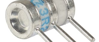
RDIP1-10-IV-UHL1
LONG-SPARK LOOP DISCHARGER MODIFIED RDIP1-10-IV-UHL1
RDIP1-10 in terms of characteristics, principle of operation and purpose does not differ from the arrester RDIP-10-IV-UHL1, being only its structural modification.
The design difference between RDIP1 and RDIP comes down to the changed shape of the loop bend, the details of the fastening unit and the method of ensuring an air gap between the arrester and the wire. The air discharge gap between the RDIP1 electrode and the wire maintains the set parameters regardless of the geometry of the wire in the span and even when the wire slips in the harness on the insulator.
| Name | Meaning |
| Voltage class, kV | 6-10 |
| Conductor | VLZ (SIP) |
| Overvoltage type | Induced |
| Packaging dimensions, cm | 71,5/55,0/43,0 |
| Unit. | PC |
| Quantity per package, pcs. | 10 |
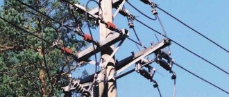
Installation of RDIP on 6-10 kV overhead lines with pin insulators
Secure the arrester with a clamp to the insulator pin.
To set the gap between the SIP-3 wire and the arrester, you can manually change the bend of the loop. Next, a universal or biting clamp is mounted. It is placed on the inside of the loop.
The air gap is adjustable. Its value for VLZ-6-10kv:
- 40mm from SIP wire
- 20mm from universal clamp
Order and delivery
We work with legal entities, payment for goods is only by non-cash payment.
To buy an RDIP-10-IV UHL1 arrester (NPO Streamer), you just need to call or write or send a request through the form on the website.
Receipt of goods Pickup
| In order to independently pick up products from the warehouse, the recipient must have a power of attorney and a passport. Warehouse opening hours: Mon–Fri: 8:00 to 17:00 |
Our delivery to the recipient's warehouse
| We are ready to deliver your order to the address you specify in any region of the Russian Federation. In Moscow: transportation of cargo weighing up to 5 tons to the buyer’s warehouse – 1,500 rubles. VAT included. In Russia: the cost is calculated depending on the weight, volume of the goods and the location of the recipient. |
Transport companies
| Delivery to the terminal of any transport company in Moscow is free. It is recommended to order wooden packaging for fragile goods. |
Installation on a tension garland
First of all, loosen the fastening of the arrester arms. After which the RDIP is separated from the fastener.
The bracket rotates 180 degrees and fits only on one shoulder.
This is done so that the arrester loop can be threaded through the SIP wire without breaking it. Both arms can now be tightened again.
Attach the mounting bracket to the top earring of the garland and set the air gap. It is measured between the central electrode on the arrester and the nearest metal part of the fittings.
If it is not possible to secure the RDIP to the garland, then use suitable fastenings for traverses and slopes.
Types of fasteners and distances for the loop arrester on VLZ-6-10kv:
Corner anchor supportIncreased corner intermediateCorner intermediateDouble chain corner intermediateDouble chain anchorCorner anchorSingle chain corner intermediate
The valve arrester uses a nonlinear resistance to extinguish the arc
For many decades, valve arresters have been widely used in electrical networks. They are a series-connected gas gap and a nonlinear resistance. In our country, resistors made of vilit, a composite material based on silicon carbide, are usually used. The higher the current, the lower the resistance of the villite resistor. When a surge voltage occurs and the arrester is triggered, the current through the resistor increases sharply and its resistance decreases. But when the pulse has passed and the self-sustaining arc discharge continues, the current drops, the resistance of the resistor increases, which leads to a decrease in the voltage at the contacts of the arrester. In this way, the arc discharge is extinguished. The valve arrester can withstand up to 20 operations.
A type of valve arrester is a magnetic valve, where a magnetic field is additionally used to extinguish the arc.
The tubular arrester, which also belongs to the spark gap, stands out somewhat from the general series. The chamber in it is not sealed and is filled with a solid substance - polyvinyl chloride. The “ground” is made in the form of a tube, the other electrode is made in the form of a rod coaxially located in this pipe. During a spark discharge, gas is produced in the thickness of the polyvinyl chloride and tends to escape. The gas flow extinguishes the arc. Tubular arresters can withstand up to 10 operations. Their main advantage is their low cost, but otherwise their characteristics are not at the highest level, so such arresters are gradually being replaced by solid-state ones.
Disadvantages of RDIP
However, a long period of operation shows that this type of protection does not always fully fulfill its functions. On some overhead lines, the number of single-phase short circuits may even increase.
In addition, tests confirm that RDIP cannot always protect the insulation on adjacent supports. That is, on the next two, where it is not installed in this phase. Here, much will depend on the brand of insulator, the distance between the supports and the level of overvoltage.
ShF-20 can even block insulators.
Here's a visual test in the lab:
Do you produce surge arresters?
No, we do not manufacture surge arresters.
There are two types of devices supplied to the world market for lightning protection devices: arresters and arresters of our production. We just don’t take spark gaps into account. In the Russian Federation, they also continue to produce tubular and valve-type arresters, although, by all accounts, they have already outlived their usefulness, for sure for lines of 35 kV and above. There are new developments, for example in China, these are various designs-combinations of surge arresters, “horns” and even tubular arresters. But all of them are at the research stage and are not commercially available.
There are many devices based on surge arresters, each manufacturer tries to bring something different, but the base is the same - varistors. And varistors require careful handling and have a certain throughput.
Arresters RMK-20, MCR
Therefore, recently, along with loop-type devices, arresters with the RMK-20 or MCR (Niled) multi-chamber system have become widely used.
It is more compact and easier to install. In terms of application and installation scheme, MCR (RMK-20) is similar to traditional long-spark ones. That is, it is also installed on each support with alternating phases.
What does RMK-20 consist of:
- multi-chamber system - discharge element
- bracket for attaching an insulator or traverse to the reinforcement
- universal wire clamp
It can also be supplemented with an operation indicator.
The design of the bracket is universal and allows you to mount RMK-20 on intermediate and anchor supports SV-105,110,164 with several types of insulation.
Is it permissible to lengthen
It is more convenient to work with a long wire, but it increases the resistance of the conductor and, accordingly, an additional voltage drop occurs across it.
To provide the required current, the device must be switched to maximum load mode, which causes rapid wear of the device. It is possible to lengthen the cable, including the return wire, but replace it with a thicker one with a larger cross-section.
Then the losses on the conductor will not change, but the mass of the cable will increase. Since the resistivity is constant for a particular metal, doubling the length of the conductor will require doubling the cross-sectional area.
In this case, it is necessary to correctly connect the plugs and terminals to the cable. They must be connected by crimping or soldering followed by insulation.
There is no clear unambiguous prohibition on lengthening from manufacturers. Special requirements for ensuring current are placed on electrode holders. However, many experts do not recommend extending the cable, stating that the device may fail, and the manufacturer will void the warranty.
Preparation for installation
Before installation, be sure to carry out an external inspection. The discharge element must be free of cracks, cuts, mechanical dents, etc. Try to bend the element using light force. It should be sufficiently elastic and immediately restore its original shape.
If the kit includes response indicators, check the integrity of the opaque glass bulb.
Initially, the arrester is supplied disassembled. Therefore, it must be assembled into a single structure. Use a bolt with nuts and washers to connect the bracket and the multi-chamber system.
Installation of RMK-20 on a pin insulator
The arrester is mounted directly on the pin under the insulator by its fastening. Moreover, the bracket should initially be slightly loosened to be able to adjust its position.
The angle of displacement of the arrester relative to the wire axis should be within 30 degrees.
The distance from the bracket to the lower skirt of the insulator is also adjustable - 30mm. The best way to do this is using a template.
After adjustment, the bracket bolts can be tightened. Tightening force 25 Nm.
There must be an air gap of a fixed size between the SIP-3 wire and the RMK-20 tip. To do this, a universal clamp is mounted on the wire.
For VLZ with SIP-3 wires, the clamp has a piercing spike.
Important note: if the wire is fixed to the insulator with a spiral binding, then the spike must pass between its turns without damaging the binding itself!
The universal clamp is tightened in a horizontal position.
Next, to adjust the air gap, slightly unscrew the bolt fastening and move the arrester in the desired direction. I can simply set the size of the air gap between the end spherical electrode and the clamp on SIP-3 according to the template.
This gap must be within the following limits:
- for VL-6-10kv - 40-60mm
- for overhead line-20kv - 50-70mm
Please note that bending the arrester without loosening its bracket is prohibited. Otherwise, you may damage the internal reinforcing element.
Design
Structurally, the SIP clamp consists of:
- Waterproof or sealed housing (the latter is preferable).
- A kind of internal “terminal” made of one or more symmetrical plates with pyramid-shaped spikes, which are located in each of the sockets.
- A fastening system based on the use of a breakaway calibrated screw head.
- Additional clamp release system designed for emergency removal.
Inside the case there is a special lubricant that seals the puncture site, preventing water and air from coming into contact with the wire. This is also facilitated by the specific shape of the teeth.
The SIP clamp is tightened with an ordinary bolt with a 13, or less often 17, head. In total, the system has two bolts - one with a breakaway head, the other a regular one, which, if necessary, can be loosened to pull out the wire and disassemble the entire structure.
There are 2 or 4 sockets for wires. They can be of different diameters, for example, 16–120 and 6–50. Here the first group of numbers is the cross-section of the main wire, the second is the additionally connected one. One of the advantages of SIP clamps is that they (within certain limits) can be adjusted to fit cables of various calibers.
There are two main types of these connectors - with a breakaway head and with a torque wrench, which can be used to set the clamping force. In models with a breaking head, breaking occurs at a force of 9 to 20 Newtons (depending on the model). The same compression force must be achieved when using a modification with a torque wrench, since it is necessary that the teeth pierce the insulation and reliably enter the metal core. In this case, the teeth are significantly deformed - this, in combination with the breaking of the head of the clamping bolt, makes the clamp for SIP disposable. The fact is that, in order to combat the formation of oxides, the plate with spikes in the clamps is made of a relatively soft aluminum alloy. This is its difference from “piercing” terminal blocks.
There is no electrical contact between the connecting screws and the serrated plates. The housings are made from various polymer materials that are UV resistant and often have additional fiberglass reinforcement.
Installation of arrester on suspended insulation PS-70
The arrester is fixed on top of the suspension insulator earring.
The angle of displacement of the arrester element from the wire axis is 30 degrees.
Having set the angle, the bracket is tightened. Next, adjust the gaps. The horizontal distance between the skirt of the upper insulator and the arrester electrode should be approximately 30mm. Once you have it out, tighten all the nuts.
The universal clamp is installed here as close as possible, close to the supporting clamp of the garland.
When installing the operation indicator, ensure its vertical position. At the same time, it should be located under the spherical electrode of the spark gap.