Application area. Definitions
7.1.1.
This chapter of the Rules applies to electrical installations of: residential buildings listed in SNiP 2.08.01-89 “Residential Buildings”; public buildings listed in SNiP 2.08.02-89 “Public buildings and structures” (except for buildings and premises listed in Chapter 7.2): administrative and domestic buildings listed in SNiP 2.09.04-87 “Administrative and domestic buildings” ; Additional requirements may apply to electrical installations of unique and other special buildings not included in the above list. Further in the text, unless otherwise specified, the word “buildings” means all types of buildings to which this chapter applies.
The requirements of this chapter do not apply to special electrical installations in medical institutions, organizations and institutions of science and scientific services, to dispatch and communication systems, as well as to electrical installations, which by their nature should be classified as electrical installations of industrial enterprises (workshops, boiler rooms, thermal points, pumping stations, laundry factories, dry cleaning factories, etc.).
7.1.2. Electrical installations of buildings, in addition to the requirements of this chapter, must meet the requirements of the chapters of Section. 1-6 PUE to the extent that they are not changed by this chapter.
7.1.3. Input device (ID) is a set of structures, devices and instruments installed at the input of the supply line into the building or its separate part.
The input device, which also includes devices and devices of outgoing lines, is called an input distribution device (IDU).
7.1.4. The main distribution board (MSB) is a distribution board through which the entire building or its separate part is supplied with electricity. The role of the main switchboard can be performed by an ASU or a low voltage switchboard of a substation.
7.1.5. Distribution point (DP) is a device in which protection devices and switching devices (or only protection devices) are installed for individual electrical receivers or their groups (electric motors, group panels).
7.1.6. A group panel is a device in which protection devices and switching devices (or only protection devices) are installed for separate groups of lamps, plug sockets and stationary electrical receivers.
7.1.7. Apartment panel - a group panel installed in an apartment and designed to connect the network that supplies lamps, plug sockets and stationary electrical receivers of the apartment.
7.1.8. Floor distribution panel is a panel installed on the floors of residential buildings and intended to supply power to apartments or apartment panels.
7.1.9. Electrical room - room. accessible only to qualified service personnel, in which VU, ASU, main switchboard and other distribution devices are installed.
7.1.10. Supply network - a network from a substation switchgear or a branch from overhead power lines to the VU, ASU, main switchboard.
7.1.11. Distribution network - a network from the VU, ASU, main switchboard to distribution points and switchboards.
7.1.12. Group network - a network from panels and distribution points to lamps, plug sockets and other electrical receivers.
REQUIREMENTS FOR CURRENT METERS
1.5.13. Each installed billing meter must have seals with the stamp of the state verifier on the screws securing the meter casing, and on the clamping cover - a seal from the energy supplying organization.
Newly installed three-phase meters must have state verification seals that are no more than 12 months old, and single-phase meters must have state verification seals that are no more than 2 years old.
1.5.14. Accounting for active and reactive electricity of three-phase current should be carried out using three-phase meters.
1.5.15. Acceptable accuracy classes of calculated active electricity meters for various metering objects are given below:
| Generators with a capacity of more than 50 MW, intersystem power lines of 220 kV and above, transformers with a capacity of 63 MV ∙ A and more | 0,5 (0,7)<*> |
| Generators with a capacity of 12 - 50 MW, intersystem power lines 110 - 150 kV, transformers with a capacity of 10 - 40 MV ∙ A | 1,0 |
| Other accounting objects | 2,0 |
<*> The value shown in parentheses refers to the counters being imported.
The accuracy class of reactive electricity meters must be selected one step lower than the corresponding accuracy class of active electricity meters.
General requirements. Electricity supply
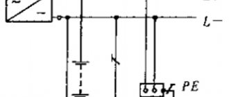
7.1.13. Electrical receivers must be powered from a 380/220 V network with a TN-S or TN-CS grounding system.
When reconstructing residential and public buildings with a network voltage of 220/127 V or 3 x 220 V, the network should be switched to a voltage of 380/220 V with a TN-S or TN-CS grounding system.
7.1.14. External power supply to buildings must meet the requirements of Chapter 1.2.
7.1.15. In dormitories of various institutions, in schools and other educational institutions, etc. the construction of built-in and attached substations is not allowed.
In residential buildings, in exceptional cases, it is allowed to place built-in and attached substations using dry-type transformers in agreement with state supervisory authorities, while sanitary requirements for limiting noise and vibration levels must be fully met in accordance with current standards.
The construction and placement of built-in, attached and free-standing substations must be carried out in accordance with the requirements of the chapters of Section. 4.
7.1.16. It is recommended that power and lighting electrical receivers be powered from the same transformers.
7.1.17. The location and layout of transformer substations must provide for the possibility of round-the-clock unhindered access to them for personnel of the energy supply organization.
7.1.18. Power supply for safety lighting and evacuation lighting must be carried out in accordance with the requirements of Chapter. 6.1 and 6.2, as well as SNiP 23-05-95 “Natural and artificial lighting”.
7.1.19. If there are elevators in the building, which are also intended for transporting fire departments, their power supply must be provided in accordance with the requirements of Chapter. 7.4.
7.1.20. Electrical networks of buildings must be designed to power advertising lighting, shop windows, facades, illumination, outdoor, fire-fighting devices, dispatch systems, local television networks, light indicators of fire hydrants, safety signs, bell and other alarms, light fencing lights, etc., in in accordance with the design specifications.
7.1.21. When supplying single-phase consumers of buildings from a multiphase distribution network, it is allowed for different groups of single-phase consumers to have common N and PE conductors (five-wire network) laid directly from the ASU; combining N and PE conductors (four-wire network with PEN conductor) is not allowed.
When supplying single-phase consumers from a multiphase supply network with branches from overhead lines, when the PEN conductor of the overhead line is common to groups of single-phase consumers powered from different phases, it is recommended to provide protective shutdown of consumers when the voltage exceeds the permissible limit, arising due to load asymmetry when the PEN breaks conductor. The disconnection must be carried out at the entrance to the building, for example, by influencing the independent release of the input circuit breaker using a maximum voltage relay, and both the phase (L) and neutral working (N) conductors must be disconnected.
When choosing devices and devices installed at the input, preference, other things being equal, should be given to devices and devices that remain operational when the voltage exceeds the permissible voltage, arising due to load asymmetry when the PEN or N conductor breaks, while their switching and other performance specifications may not be met.
In all cases, it is prohibited to have switching contact and non-contact elements in PE and PEN conductor circuits.
Connections that can be disassembled with a tool are allowed, as well as connectors specially designed for this purpose.
Input devices, distribution boards, distribution points, group boards
7.1.22. A VU or ASU must be installed at the entrance to the building. One or more VU or ASU may be installed in a building.
If there are several economically separate consumers in a building, it is recommended that each of them install an independent VU or ASU.
The ASU is also allowed to supply power to consumers located in other buildings, provided that these consumers are functionally connected.
For branches from overhead lines with a rated current of up to 25 A, the VU or ASU may not be installed at the inputs to the building if the distance from the branch to the group panel, which in this case performs the functions of the VU, is no more than 3 m. This section of the network must be carried out with a flexible copper cable with with a conductor cross-section of at least 4 mm2, flame retardant, laid in a steel pipe, and the requirements for ensuring a reliable contact connection with the branch wires must be met.
For air input, surge suppressors must be installed.
7.1.23. Before entering buildings, it is not allowed to install additional cable boxes to separate the service scope of external supply networks and networks inside the building. Such separation must be carried out in the ASU or main switchboard.
7.1.24. VU, ASU, main switchboard must have protection devices on all inputs of supply lines and on all outgoing lines.
7.1.25. Control devices must be installed at the input of supply lines to the VU, ASU, and main switchboards. On outgoing lines, control devices can be installed either on each line, or be common to several lines.
A circuit breaker should be considered as a protection and control device.
7.1.26. Control devices, regardless of their presence at the beginning of the supply line, must be installed at the inputs of the supply lines in retail premises, utilities, administrative premises, etc., as well as in consumer premises that are administratively and economically isolated.
7.1.27. The floor panel must be installed at a distance of no more than 3 m along the length of the electrical wiring from the supply riser, taking into account the requirements of Chapter. 3.1.
7.1.28. VU, ASU, main switchboard, as a rule, should be installed in electrical switchboard rooms accessible only to maintenance personnel. In areas prone to flooding, they should be installed above the flood level.
VU, ASU, main switchboard can be located in rooms allocated in operational dry basements, provided that these rooms are accessible to maintenance personnel and are separated from other rooms by partitions with a fire resistance limit of at least 0.75 hours.
When placing VU, ASU, main switchboards, distribution points and group panels outside electrical switchboard rooms, they must be installed in places convenient and accessible for maintenance, in cabinets with an enclosure protection degree of at least IP31.
The distance from pipelines (water supply, heating, sewerage, internal drains), gas pipelines and gas meters to the installation site must be at least 1 m.
7.1.29. Electrical switchboard rooms, as well as VU, ASU, main switchboards, are not allowed to be located under toilets, bathrooms, showers, kitchens (except for apartment kitchens), sinks, washing and steam rooms of bathhouses and other rooms associated with wet technological processes, except in cases where Special measures have been taken for reliable waterproofing to prevent moisture from entering the premises where the switchgear is installed.
It is not recommended to lay pipelines (plumbing, heating) through electrical rooms.
Pipelines (plumbing, heating), ventilation and other ducts laid through electrical switchboard rooms should not have branches within the room (with the exception of a branch to the heating device of the switchboard room itself), as well as hatches, valves, flanges, valves, etc.
Laying gas and pipelines with flammable liquids, sewerage and internal drains through these premises is not permitted.
Doors to electrical rooms must open outward.
7.1.30. The premises in which ASUs and main switchboards are installed must have natural ventilation and electric lighting. The room temperature should not be lower than +5 oC.
7.1.31. Electrical circuits within the VU, ASU, main switchboard, distribution points, group panels should be made with wires with copper conductors.
Electrical wiring and cable lines
7.1.32. Internal wiring must be carried out taking into account the following:
1. Electrical installations of different organizations, separate administratively and economically, located in the same building, can be connected by branches to a common supply line or fed by separate lines from the ASU or main switchboard.
2. It is allowed to connect several risers to one line. On branches to each riser supplying apartments in residential buildings with more than 5 floors, a control device combined with a protection device should be installed.
3. In residential buildings, lamps in staircases, lobbies, halls, floor corridors and other indoor premises outside apartments must be powered via independent lines from the ASU or separate group panels powered from the ASU. Connecting these lamps to floor and apartment panels is not allowed.
4. For staircases and corridors with natural light, it is recommended to provide automatic control of electric lighting depending on the illumination created by natural light.
5. It is recommended to supply power to electrical installations of non-residential buildings using separate lines.
7.1.33. Supply networks from substations to VU, ASU, main switchboard must be protected from short-circuit currents.
7.1.34. Cables and wires with copper conductors should be used in buildings
Supply and distribution networks, as a rule, must be made of cables and wires with aluminum conductors if their design cross-section is 16 mm2 or more.
The power supply of individual electrical receivers related to the engineering equipment of buildings (pumps, fans, heaters, air conditioning units, etc.) can be provided by wires or cables with aluminum conductors with a cross-section of at least 2.5 mm2.
In museums, art galleries, and exhibition spaces, it is permitted to use lighting busbar trunking systems with a degree of protection IP20, in which the branch devices to the lamps have detachable contact connections located inside the busbar trunking box at the time of switching, and busbar trunking systems with a degree of protection IP44, in which the branching devices to the lamps are made with using plug connectors that ensure the branch circuit is broken until the plug is removed from the socket.
In these premises, lighting busbars must be powered from distribution points by independent lines.
In residential buildings, the cross-sections of copper conductors must correspond to the calculated values, but not be less than those indicated in Table 7.1.1.
1 Until 2001, according to the existing construction backlog, the use of wires and cables with aluminum conductors was allowed.
Table 7.1.1. The smallest permissible cross-sections of cables and wires of electrical networks in residential buildings.
| Line names | Smallest cross-section of cables and wires with copper conductors, mm2 |
| Group network lines | 1,5 |
| Lines from floor to apartment panels and to the settlement meter | 2,5 |
| Distribution network lines (risers) for supplying apartments | 4 |
7.1.35. In residential buildings, laying vertical sections of the distribution network inside apartments is not allowed.
It is prohibited to lay wires and cables from the floor panel in a common pipe, common box or channel that supply lines to different apartments.
Fire-retardant installation in a common pipe, common box or channel of building structures made of non-combustible materials, wires and cables of apartment supply lines together with wires and cables of group lines of working lighting of staircases, floor-by-floor corridors and other indoor premises is allowed.
7.1.36. In all buildings, group network lines laid from group, floor and apartment switchboards to general lighting fixtures, plug sockets and stationary electrical receivers must be three-wire (phase - L, neutral working - N and neutral protective - PE conductors).
Combining zero working and zero protective conductors of different group lines is not allowed.
The neutral working and neutral protective conductors are not allowed to be connected on panels under a common contact terminal.
Conductor cross-sections must meet the requirements of clause 7.1.45.
7.1.37. Electrical wiring in the premises should be replaced: hidden - in the channels of building structures, embedded pipes; open - in electrical skirting boards, boxes, etc.
In technical floors, undergrounds, unheated basements, attics, ventilation chambers, damp and especially damp rooms, it is recommended that electrical wiring be carried out openly.
In buildings with building structures made of non-combustible materials, permanent, monolithic installation of group networks is allowed in the grooves of walls, partitions, ceilings, under plaster, in the floor preparation layer or in the voids of building structures, carried out with cable or insulated wires in a protective sheath. The use of permanently embedded wiring in panels of walls, partitions and ceilings, made during their manufacture at construction industry factories or carried out in the mounting joints of panels during the installation of buildings, is not allowed.
7.1.38. Electrical networks laid behind impenetrable suspended ceilings and in partitions are considered as hidden electrical wiring and should be installed: behind ceilings and in the voids of partitions made of flammable materials in metal pipes with localization capabilities and in closed boxes; behind ceilings and in partitions made of non-combustible materials 2 - in pipes and ducts made of non-flammable materials, as well as flame retardant cables. In this case, it must be possible to replace wires and cables.
2 Suspended ceilings made of non-combustible materials mean those ceilings that are made of non-combustible materials, while other building structures located above suspended ceilings, including interfloor ceilings, are also made of non-combustible materials.
7.1.39. In rooms for cooking and eating, with the exception of apartment kitchens, open laying of cables is allowed. Open wiring of wires in these rooms is not allowed.
In apartment kitchens, the same types of electrical wiring can be used as in living rooms and corridors.
7.1.40. In saunas, bathrooms, toilets, showers, as a rule, hidden electrical wiring should be used. Open cable routing is allowed.
In saunas, bathrooms, toilets, showers, laying wires with metal sheaths, in metal pipes and metal sleeves is not allowed.
In saunas for zones 3 and 4 according to GOST R 50571.12-96 “Electrical installations of buildings. Part 7. Requirements for special electrical installations. Section 703: Premises Containing Sauna Heaters" electrical wiring with an insulation temperature rating of 170oC must be used.
7.1.41. Electrical wiring in attics must be carried out in accordance with the requirements of Section. 2.
7.1.42. Through the basements and technical undergrounds of sections of the building, it is allowed to lay power cables with a voltage of up to 1 kV, supplying electrical receivers of other sections of the building. The specified cables are not considered as transit; laying transit cables through basements and technical undergrounds of buildings is prohibited.
7.1.43. Open laying of transit cables and wires through storerooms and warehouses is not permitted.
7.1.44. The lines supplying refrigeration units of trade and public catering enterprises must be laid from the ASU or main switchboard of these enterprises.
7.1.45. The selection of conductor cross-sections should be carried out in accordance with the requirements of the relevant chapters of the PUE.
Single-phase two- and three-wire lines, as well as three-phase four- and five-wire lines when supplying single-phase loads, must have a cross-section of zero working (N) conductors equal to the cross-section of phase conductors.
Three-phase four- and five-wire lines when supplying three-phase symmetrical loads must have a cross-section of zero working (N) conductors equal to the cross-section of phase conductors, if the phase conductors have a cross-section of up to 16 mm2 for copper and 25 mm2 for aluminum, and for large cross-sections - at least 50 % cross-section of phase conductors.
The cross-section of PEN conductors must be at least the cross-section of N conductors and at least 10 mm2 for copper and 16 mm2 for aluminum, regardless of the cross-section of the phase conductors.
The cross-section of PE conductors must be equal to the cross-section of phase conductors with a cross-section of the latter up to 16 mm2, 16 mm2 with a cross-section of phase conductors from 16 to 35 mm2 and 50% of the cross-section of phase conductors with larger cross-sections.
The cross-section of PE conductors not included in the cable must be at least 2.5 mm2 - in the presence of mechanical protection and 4 mm2 - in its absence.
PUE Chapter 7.1 Electrical equipment of residential and public buildings
APPLICATION AREA. DEFINITIONS
7.1.1. This chapter of the Rules applies to electrical equipment of residential buildings listed in chapter SNiP 2.08.01-89* (ed. 1995) “Residential buildings.”, SNiP 2.08.02-89 “Public buildings and structures. Design standards. General part”, as well as for electrical equipment of club institutions, entertainment enterprises and indoor sports buildings and structures with less than 300 seats in the auditorium, auxiliary buildings and premises of industrial enterprises.
The requirements of this chapter do not apply to special electrical installations in medical institutions, organizations and institutions of science and scientific services, cultural institutions, dispatch and communication systems, as well as electrical installations, which by their nature should be classified as electrical installations of industrial enterprises (workshops, boiler rooms , heating points, pumping stations, laundry factories, dry cleaning factories, etc.).
Additional requirements may be imposed on the electrical equipment of unique residential and public buildings.
7.1.2. Electrical equipment of residential and public buildings, in addition to the requirements of this chapter, must meet the requirements of other sections and chapters of the PUE to the extent that they are not changed by this chapter.
7.1.3. An input device (ID) is a set of structures, devices and devices installed at the input of the supply line into a building or its separate part.
An input distribution device (IDU) is a set of structures, devices and instruments installed at the input of the supply line into a building or into a separate part of it, as well as on lines extending from the IDU.
7.1.4. The main distribution board (MSB) is the distribution board through which electricity is supplied to the entire building or its separate part. The role of the main switchboard can be performed by an ASU or a low voltage switchboard of a substation.
7.1.5. A secondary distribution board (SDB) is a distribution board that receives electricity from the main switchboard or ASU and distributes it to group panels and distribution points of the building.
7.1.6. A distribution point or group panel is a point or panel on which protection devices and switching devices of individual electrical receivers or their groups (electric motors, lamps) are installed.
7.1.7. An apartment panel is a group panel installed on a staircase, in halls, floor corridors or in apartments of residential buildings and intended for connecting group networks of apartments.
7.1.8. A floor panel is a group panel installed on the floors and intended to power apartment panels. The floor panel is installed on the staircase, in the hall or in the corridor on the floor.
7.1.9. A switchboard room is a locked room, accessible only to maintenance personnel, in which VU, ASU, main switchboard, VR switchboard, etc. are installed.
7.1.10. The supply network is the network from the switchgear of a substation or branch from the power line to the ASU, as well as from the ASU to the main switchboard and VRShch and to distribution points or group panels.
7.1.11. A group network is a network that supplies lamps and sockets.
7.1.12. A distribution network is a network that supplies power electrical receivers.
GENERAL REQUIREMENTS
7.1.13. Power supply for electrical receivers must be provided from a 380/220 V network with a solidly grounded neutral. In justified cases, power supply from a network above 380/220 V with a solidly grounded neutral is allowed. In existing buildings with 220/127 V networks, the networks should be converted to 380/220 V.
7.1.14. Electrical networks of buildings must, if necessary, provide the ability to power advertising lighting, shop windows, facades, illumination, outdoor, fire-fighting devices, dispatch systems, light signs, sound and other alarms, as well as power supply for light fencing lights.
TRANSFORMER SUBSTATIONS
7.1.15. In residential buildings (apartment buildings and dormitories), dormitory buildings of hospitals, sanatorium-resort institutions, rest homes, social security institutions, as well as in institutions for mothers and children, in secondary schools and institutions for raising children, in educational institutions for training and advanced training of workers and other workers, secondary specialized educational institutions, etc. the construction of built-in and attached substations is not permitted. In other premises of public buildings, it is permitted to place built-in and attached substations, subject to the requirements of Chapter. 4.2. In these rooms, transformers must be installed on shock absorbers.
7.1.16. Switchgears up to 1 kV and higher should, as a rule, be placed in different rooms. In this case, switchgear rooms up to 1 kV and above must have separate lockable entrances. It is allowed to place switchgear up to 1 kV and higher in one room if they are operated by the same organization.
The requirement to place switchgear up to 1 kV and higher in separate rooms does not apply to package transformer substations. The high-voltage part of the package substation, if necessary, is sealed by the organization under whose jurisdiction it is located.
INPUT DEVICES, DISTRIBUTION BOARDS DISTRIBUTION POINTS AND GROUP BOARDS
7.1.17. Entrances to buildings must be equipped with a VU or ASU. Before entering the building, it is not allowed to install additional cable boxes to separate the service scope of external supply networks and networks inside buildings. Such separation must be ensured in the ASU or main switchboard.
7.1.18. Protection devices and control devices must be installed on the VU or ASU. On VU and ASU with a current of no more than 25 A, control devices may not be installed. When installing protection devices for currents up to 25 A on branches from overhead lines, VU or ASU are not required to be installed at building inputs.
It is permissible not to install protection devices at the input of the supply line into the building if the protection is available at the beginning of the branch or the power supply to the VU or ASU is provided by a separate line. Protection devices must be installed on each line extending from the distribution board, point or panel.
The control device can be common to several lines. Moreover, in the case of combining the control unit with a distribution board and the presence of a control device with a fixed off position at the input, the installation of an additional general control device is not necessary.
7.1.19. Control devices, regardless of the presence of the same devices at the beginning of the supply line or at its branch, must be installed at the inputs of supply lines into retail premises, utilities, administrative premises, etc., as well as in the premises of consumers isolated in administrative areas. economically.
7.1.20. External supply networks (from substations to VU, ASU) must be protected only from short-circuit currents.
7.1.21. When placing protection devices in addition to the requirements of Ch. 3.1 the following requirements must be followed:
1. In residential and public buildings and premises, automatic switches and fuses at distribution points and group panels should be installed only in phase wire circuits.
2. When installing panels that combine the functions of apartment and floor panels on staircases at a distance of no more than 3 m from the stair riser, a separate floor panel is not required to be installed.
7.1.22. As a rule, VU, ASU, main switchboard should be installed in switchboard rooms accessible only to maintenance personnel, or in locked cabinets or niches. In areas prone to flooding, they should be installed above the flood level.
For one- and two-story residential buildings that do not have common staircases, the VU and ASU can be installed outside on the wall of the building. In this case, they must have an appropriate degree of protection.
It is allowed to place VU, ASU and main switchboards in rooms allocated in dry basements or technical undergrounds, provided that these rooms are easily accessible to maintenance personnel and are separated from other rooms by fireproof partitions with a fire resistance limit of at least 0.75 hours.
When placing VU, ASU, main switchboard, VRShch, distribution points and group panels outside switchboard rooms, the following requirements must be met:
1. Devices must be located in places that are convenient and accessible for maintenance.
2. Points and shields, as a rule, should be installed in niches, drawers or covered with casings.
Points and shields should not have open, non-insulated live parts.
3. Devices must be installed at a distance of at least 0.5 m from pipelines (water supply, heating, sewerage, internal drains), gas pipelines and gas meters.
7.1.23. Input distribution devices, switchboards, shields, points installed in special switchboard rooms or in lockable niches made of fireproof structures may not have rear and side walls and doors.
7.1.24. Switchboard rooms, as well as VU and ASU are not allowed to be located under toilets, bathrooms, showers, kitchens (except for apartment kitchens), sinks, washing and steam rooms of baths, washing rooms of laundries, dry cleaners, etc.
Pipelines (water supply, heating, sewerage, internal drains), ventilation and other ducts laid through switchboard rooms (with the exception of a branch to the heating device of the switchboard room itself) should not have branches within the room, as well as hatches, valves, flanges, revisions , valves, etc. Laying gas pipelines and pipelines with flammable liquids through these premises is not permitted.
Doors to electrical rooms must open outward.
7.1.25. The premises in which the VU, ASU, main switchboard, VRShch, distribution points, switchboards and shields are installed must have natural ventilation and electric lighting, as well as heating, ensuring a room temperature of at least +5 °C.
7.1.26. Electrical circuits of VU, ASU, main switchboard, VRShch, distribution points, group panels may be made with wires with aluminum or aluminum-copper conductors.
ELECTRICAL WIRING AND CABLE LINES
7.1.27. When performing internal electrical wiring and cable lines, you must be guided by the following:
1. Electrical installations of different organizations, separate administratively and economically, located in the same building, can be connected by branches to a common supply line or by separate lines of the ASU, main switchboard or VRSHCH.
It is allowed to power electrical installations of consumers in the non-residential sector and apartments from a common supply line, provided that separate control devices are installed at branch points. In both cases, the quality of the voltage must be ensured (see Chapter 1.2).
2. It is allowed to connect several risers to one line. A control device should be installed on the branch to the riser supplying apartments in residential buildings with more than five floors.
3. In residential buildings, lamps in staircases, hallways, corridors and other indoor premises outside apartments must be powered via independent lines from the ASU or separate group panels powered from the ASU. Connecting them to apartment panels is not allowed.
4. It is allowed to connect up to 60 incandescent or fluorescent lamps per phase with a power of up to 65 W each to group lighting lines of staircases, floor corridors, halls, lobbies, basements, technical undergrounds and attics of residential and public buildings.
5. For staircases and corridors with natural light, it is recommended to provide automatic control of electric lighting depending on the illumination created by natural light.
7.1.28. In residential buildings, the risers of the supply networks of apartments must be laid along staircases. Laying power supply risers inside apartments is not permitted.
Laying in a common pipe, common box or channel made of fireproof building structures, etc. is allowed. wires of supply lines of apartments along with wires of working lighting of staircases, corridors and other indoor premises.
The laying of apartment group networks from the main panel to the entrance to the apartment should be carried out in independent channels, pipes, boxes, etc., i.e., separately from the group lines of other apartments.
In derogation from the requirements of 2.1.15, it is allowed to jointly lay up to 12 wires of group networks of apartments in residential buildings in one channel.
It is allowed to combine the neutral wires of the supply lines of apartments and the working lighting lines of staircases and corridors.
7.1.29. Laying lines in premises, as a rule, should be done hidden. It is recommended to carry out open installation of networks in technical floors and undergrounds, unheated basements, heating points, ventilation chambers, pump rooms, in damp and especially damp rooms.
Vertical sections (risers) of electrical network lines must be made: with unprotected wires - in pipes, ducts, channels of building structures, cables, busbars - in shafts and channels of building structures.
Places where lines pass through interfloor ceilings must be sealed with fireproof materials.
In residential and public buildings, as well as in the bathrooms of residential buildings, it is allowed to carry out hidden wiring, without pipes, with special wires (for example, APPV) in the grooves of the walls, under plaster, etc.
In buildings made of fireproof building structures, permanently enclosed installation of group network wires in panels of walls, partitions and ceilings is allowed when they are manufactured at construction industry factories.
7.1.30. In premises for cooking and eating, with the exception of apartments, open wiring is prohibited.
In apartment kitchens, the same types of electrical wiring can be used as in living rooms and corridors. In bathrooms, showers and toilets, as a rule, hidden electrical wiring should be used; Open electrical wiring with protected wires and cables is allowed.
When laying wires and cables, the requirements of the “Instructions for the selection and use of installation wires” must be taken into account, including the requirements for premises and buildings made of combustible materials, as well as the “Unified Technical Instructions for the selection and use of electrical cables”.
7.1.31. Electrical wiring in attics must be carried out in accordance with the requirements of Sec. 2.1. These requirements do not apply to attics used as a technical floor and having fireproof building structures.
7.1.32. Electrical networks laid behind non-passable suspended ceilings are considered as hidden electrical conductors, and they should be installed: behind ceilings made of combustible materials - in metal pipes, boxes, metal hoses; behind ceilings made of fireproof and fire-resistant materials - in vinyl plastic or similar pipes, boxes, metal hoses, as well as cables and protected wires with sheaths made of fire-resistant materials. It must be possible to replace wires and cables.
Table 7.1.1. The smallest permissible cross-sections of cables and wires of electrical networks in buildings
Line names
| Smallest cross-section of cables and wires, mm2 | ||
| copper | aluminum and aluminum-copper | |
| Group and distribution network lines | 1 | 2,5 |
| Lines to apartment panels and to the settlement meter | 2,5 | 4 |
| Power lines and risers for powering apartments and dormitory rooms | 4 | 6 |
7.1.33. The cross-sections of cables and wires of the electrical network of buildings must be no less than those given in table. 7.1.1.
Three-phase lines in residential buildings must have a cross-section of neutral conductors equal to the cross-section of phase conductors, if the phase conductors have a cross-section of up to 25 mm2 (for aluminum), and for large cross-sections - at least 50% of the cross-section of phase conductors. The cross-sections of zero working and neutral protective conductors in three-wire lines must be no less than the cross-section of phase conductors.
Zero working and zero protective conductors must comply with the requirements of Chapter. 1.7.
In residential and public buildings, group network lines laid from group panels to plug sockets must be three-wire (phase, neutral working and neutral protective conductor). Power supply to stationary single-phase electrical receivers should be carried out using three-wire lines. At the same time, the neutral working and neutral protective conductors should not be connected on the shield under one contact clamp.
INTERNAL ELECTRICAL EQUIPMENT
7.1.34. Lamps and other lighting devices in all rooms must be installed and located so that they can be safely serviced using conventional technical means (ladders, stepladders, etc.). If this is not possible, special devices must be provided (sliding towers, walking bridges, etc.). It is allowed to service lamps located at a height of no more than 5 m from ladders and stepladders.
7.1.35. In rooms for cooking and eating, with the exception of kitchens in apartments, lamps with incandescent lamps installed above workplaces (stoves, tables, etc.) must have protective glass underneath. For luminaires with fluorescent lamps, the presence of meshes or grilles is sufficient, or lamp holders must be used in the luminaires, the design of which prevents the lamps from falling out.
7.1.36. In bathrooms, showers and restrooms of apartments, hotels and dormitories, the housings of lamps with incandescent lamps and sockets must be made of insulating material.
7.1.37. Installation of sockets in bathrooms, showers, locker rooms at showers and in soap rooms of baths, steam rooms, washing rooms of laundries is not allowed.
In the bathrooms of apartments, hotels, and dormitories, it is allowed to install sockets connected to the network through isolating transformers or residual current devices (RCDs) in accordance with the “Temporary instructions for the use of residual current devices in electrical installations of residential buildings” (1997, Glavgosenergonadzor of Russia) ( see chapter 1.1).
In secondary schools and child care institutions in rooms for children, sockets must be installed at a height of 1.8 m from the floor. The installation height of sockets in other public buildings and residential premises is chosen to be convenient for connecting electrical appliances to them, depending on the purpose of the room and interior design.
It is allowed to install sockets and switches in special wall panels made at construction industry factories, without the use of embedded boxes.
Sockets should be as far as possible from grounded parts (pipelines, sinks) and should be at a distance of at least 0.5 m from them. For kitchens of residential apartments and public buildings, this distance is not standardized.
In the distribution network of public catering and retail enterprises, sockets are installed according to technical specifications, but their installation height should not exceed 1.3 m.
7.1.38. Switches for work, emergency and evacuation lighting in retail premises of shops, canteens and others intended for the presence of a large number of people must be accessible only to service personnel.
7.1.39. In bathrooms, lavatories, soap rooms, steam rooms, washing rooms, laundries, etc. switches should not be installed. Installation of switches in washbasin rooms is permitted.
7.1.40. It is recommended to install switches on the wall near the door on the side of the door handle: they can be installed under the ceiling with control using a cord. The height of installation of switches on the wall should be taken equal to 1.5 m, with the exception of secondary schools and preschool institutions, in rooms for children, where switches should be installed at a height of 1.8 m from the floor.
7.1.41. A light should be installed above each main entrance to the building.
7.1.42. House signs and fire hydrant signs must be illuminated.
POWER EQUIPMENT
7.1.43. Electric motors serving general building installations (pumps, fans, elevators, etc.), as well as their protective and starting devices, must be accessible only to maintenance personnel. The exception is the control buttons for elevators, fire-fighting devices and ventilation. Electric motor starting devices, in addition, must be located in compliance with the requirements given in Chapter. 5.3.
7.1.44. One line should supply no more than four elevators located in different, unconnected staircases and hallways. If there are two or more elevators of the same purpose in the staircase or elevator hall, they must be powered from two lines connected directly to the ASU or main switchboard; the number of elevators connected to one line is not limited.
7.1.45. Power supply to electrical receivers of fire protection systems should be carried out in accordance with their category of power supply reliability. In the absence of a technological reserve, the fire pump electric motor must be powered via two lines, one of which must be connected directly to the substation panel, ASU or main switchboard. Switching from one line to another can be done manually or automatically.
7.1.46. Installation of electric motors in the attics of buildings is permitted provided that sound insulation requirements are met to ensure standardized noise levels.
Electric motors, distribution and group panels, separately installed switching devices and protection devices must have a protection degree of IP44. With a lower degree of protection, they should be installed in cabinets with a degree of protection IP44 or in separate rooms with fences made of fire-resistant materials.
ELECTRICITY ACCOUNTING
7.1.47. In apartment-type residential buildings, one single-phase billing meter should be installed for each apartment. If necessary, it is allowed to install one three-phase meter.
7.1.48. Calculation meters in public buildings that house several electricity consumers must be provided for each consumer, isolated in administrative and economic terms (studio, shops, workshops, warehouses, housing maintenance offices, etc.).
7.1.49. In public buildings, estimated electricity meters must be installed on the ASU, at the points of balance demarcation with the energy supply organization. If there are built-in or attached transformer substations, the power of which is fully used by consumers of a given building, the calculated meters should be installed at the inputs of power transformers on a combined low-voltage switchboard, which is also the building’s ASU.
ASU and metering devices for different subscribers located in the same building may be installed in one common room. By agreement with the energy supplying organization, settlement meters can be installed at one of the consumers, from which the ASU supplies other consumers located in the building. At the same time, meters should be installed at the inputs of the supply lines to the premises of these other consumers for settlements with the main consumer of electricity.
7.1.50. Estimated meters for the general house load of residential buildings (staircase lighting, house management offices, yard lighting, etc.) are recommended to be installed in ASU cabinets or on main switchboard panels.
7.1.51. It is recommended to place residential meters together with protection devices (fuses, circuit breakers) and switches (for meters) on common apartment panels.
Apartment panels should be placed on the staircase, in the hall or in the common floor corridor: they can also be installed in the front of the apartment. Apartment panels should be installed, as a rule, in niches, if this is allowed by the building structure. When installed on a staircase, apartment panels must be located in locked cabinets with openings for taking meter readings.
7.1.52. After the meter connected directly to the power supply network, a protection device must be installed. It should be installed as close as possible to the meter, no further than 10 m along the length of the electrical wiring. If several lines equipped with protection devices extend after the meter, installation of a common protection device after the meter is not required.
7.1.53. In front of the meter, which is installed on the apartment panel located in the front of the apartment in the niches, a switch or two-pole switch must be installed for safe replacement of the meter.
GROUNDING AND GROUNDING
7.1.54. Grounding and grounding of electrical installations should be carried out in accordance with the requirements of Chapter. 1.7.
7.1.55. In the bathrooms of residential and public buildings and in bathhouses, there are metal bathtub bodies, and in shower trays, the trays must be connected by metal conductors to metal water supply pipes.
7.1.56. In rooms with suspended ceilings that have metal structures and parts, the metal housings of lamps built into suspended ceilings or installed behind them should be grounded.
7.1.57. In rooms where grounding of lamps is not required, the metal hook for hanging lamps must be insulated.
7.1.58. In residential and public buildings, metal cases of stationary and portable electrical receivers belonging to devices of protection class 1 according to GOST 27570.0 must be zeroed.
neutral protective conductors intended for grounding metal enclosures must be laid from group panels (distribution points).
Back Next
Internal electrical equipment
7.1.46. In food preparation rooms, except for apartment kitchens, lamps with incandescent lamps installed above workplaces (stoves, tables, etc.) must have protective glass underneath. Lamps with fluorescent lamps must have grilles or grids or lamp holders that prevent the lamps from falling out.
7.1.47. In bathrooms, showers and lavatories, only electrical equipment should be used that is specifically designed for installation in the relevant areas of these premises in accordance with GOST R 50571.11-96 “Electrical installations of buildings. Part 7. Requirements for special electrical installations. Section 701 - Bathrooms and Shower Facilities" and the following requirements must be met:
- — electrical equipment must have a degree of protection against water not lower than: in zone 0 — IPx7;
- in zone 1 - IPx5;
- in zone 2 - IPx4 (IPx5 - in public baths);
- in zone 3 - IPx1 (IPx5 - in public baths);
- — in zone 1 only water heaters can be installed;
7.1.48. Installation of plug sockets in bathrooms, showers, soap rooms of baths, rooms containing heaters for saunas (hereinafter referred to as “saunas”), as well as in washing rooms of laundries is not allowed, with the exception of bathrooms in apartments and hotel rooms.
In the bathrooms of apartments and hotel rooms, it is allowed to install plug sockets in zone 3 in accordance with GOST R 50571.11-96, connected to the network through isolation transformers or protected by a residual current device that responds to a differential current not exceeding 30 mA.
Any switches and sockets must be located at a distance of at least 0.6 m from the doorway of the shower stall.
7.1.49. In buildings with a three-wire network (see clause 7.1.36.), plug sockets with a current of at least 10 A with a protective contact must be installed.
Plug sockets installed in apartments, living rooms in dormitories, as well as in rooms for children in child care institutions (kindergartens, nurseries, schools, etc.) must have a protective device that automatically closes the sockets of the socket when the plug is removed.
7.1.50. The minimum distance from switches, sockets and electrical installation elements to gas pipelines must be at least 0.5 m.
7.1.51. It is recommended to install switches on the wall on the side of the door handle at a height of up to 1 m; they can be installed under the ceiling with control using a cord.
In rooms for children in children's institutions (kindergartens, nurseries, schools, etc.), switches should be installed at a height of 1.8 m from the floor.
7.1.52. In saunas, bathrooms, toilets, soap rooms, steam rooms, washing rooms, laundries, etc. installation of switchgear and control devices is not permitted.
In washbasin rooms and zones 1 and 2 (GOST R 50571.11-96) of bathrooms and shower rooms, it is allowed to install switches operated by a cord.
7.1.53. Switching devices for lighting networks in attics that have building structure elements (roofing, trusses, rafters, beams, etc.) made of flammable materials must be installed outside the attic.
7.1.54. Switches for work lamps, safety and evacuation lighting of premises intended for the presence of a large number of people (for example, retail premises of shops, canteens, hotel lobbies, etc.) must be accessible only to service personnel.
7.1.55. A lamp should be installed above each entrance to the building.
7.1.56. House license plates and fire hydrant signs installed on exterior walls of buildings must be illuminated. Electric light sources for license plates and hydrant indicators must be powered from the internal lighting network of the building, and fire hydrant indicators installed on external lighting poles must be powered from the external lighting network.
7.1.57. Fire safety devices and security alarms, regardless of the category of reliability of the building's power supply, must be powered from two inputs, and in their absence, by two lines from one input. Switching from one line to another should be automatic.
7.1.58. Electric motors, distribution points, separately installed switching devices and protective devices installed in the attic must have a degree of protection of at least IP44.
Electricity metering
7.1.59. In residential buildings, one single- or three-phase billing meter (with three-phase input) should be installed for each apartment.
7.1.60. Calculation meters in public buildings that house several electricity consumers must be provided for each consumer, isolated in administrative and economic terms (studio, shops, workshops, warehouses, housing maintenance offices, etc.).
7.1.61. In public buildings, estimated electricity meters must be installed on the ASU (main switchboard) at the points of balance demarcation with the energy supply organization. If there are built-in or attached transformer substations, the power of which is fully used by consumers of a given building, the calculated meters should be installed at the low-voltage terminals of power transformers on combined low-voltage switchboards, which are also the building’s ASU.
ASU and metering devices for different subscribers located in the same building may be installed in one common room. By agreement with the energy supplying organization, settlement meters can be installed at one of the consumers, from which the ASU supplies other consumers located in the building. At the same time, control meters should be installed at the inputs of the supply lines in the premises of these other consumers for settlements with the main subscriber.
7.1.62. Estimated meters for the general house load of residential buildings (lighting of staircases, building management offices, yard lighting, etc.) are recommended to be installed in ASU cabinets or on main switchboard panels.
7.1.63. It is recommended to place residential meters together with protection devices (circuit breakers, fuses).
When installing apartment panels in the hallways of apartments, meters, as a rule, should be installed on these panels; installation of meters on floor panels is allowed.
7.1.64. To safely replace a meter directly connected to the network, a switching device must be provided in front of each meter to remove voltage from all phases connected to the meter.
Disconnecting devices for removing voltage from settlement meters located in apartments must be located outside the apartment.
7.1.65. After the meter connected directly to the network, a protection device must be installed. If several lines equipped with protection devices extend after the meter, installation of a common protection device is not required.
7.1.66. It is recommended to equip residential buildings with remote meter reading systems.
ACCOUNTING USING INSTRUMENTATION TRANSFORMERS
1.5.16. The accuracy class of current and voltage transformers for connecting calculated electricity meters should be no more than 0.5. It is allowed to use voltage transformers of accuracy class 1.0 to switch on calculated meters of accuracy class 2.0.
To connect technical metering meters, it is allowed to use current transformers of accuracy class 1.0, as well as built-in current transformers of accuracy class below 1.0, if the installation of additional sets of current transformers is required to obtain accuracy class 1.0.
Voltage transformers used to connect technical metering meters may have an accuracy class below 1.0.
1.5.17. It is allowed to use current transformers with an increased transformation ratio (according to the conditions of electrodynamic and thermal resistance or busbar protection), if at the maximum load of the connection the current in the secondary winding of the current transformer is at least 40% of the rated current of the meter, and at a minimum operating load - at least 5 %.
1.5.18. The connection of the current windings of meters to the secondary windings of current transformers should, as a rule, be carried out separately from the protection circuits and together with electrical measuring instruments.
It is allowed to connect current circuits together if their separate connection requires the installation of additional current transformers, and the joint connection does not lead to a decrease in the accuracy and reliability class of the current transformer circuits used for metering and provides the necessary characteristics of relay protection devices.
The use of intermediate current transformers to switch on metering meters is prohibited (for an exception, see 1.5.21).
1.5.19. The load of the secondary windings of the instrument transformers to which the meters are connected should not exceed the rated values.
The cross-section and length of wires and cables in the voltage circuits of rated meters must be selected such that the voltage loss in these circuits is no more than 0.25% of the rated voltage when powered by voltage transformers of accuracy class 0.5 and no more than 0.5% when powered by voltage transformers of accuracy class 1.0. To ensure this requirement, it is allowed to use separate cables from voltage transformers to meters.
Voltage losses from voltage transformers to technical metering meters should be no more than 1.5% of the rated voltage.
1.5.20. To connect meter meters on power lines of 110 kV and above, it is allowed to install additional current transformers (in the absence of secondary windings for connecting meters, to ensure the meter operates in the required accuracy class, according to the load conditions on the secondary windings, etc.). See also 1.5.18.
1.5.21. For 110 and 220 kV bypass switches with built-in current transformers, it is allowed to reduce the accuracy class of these current transformers by one step relative to that specified in 1.5.16.
For a 110 kV bypass switch and a 110 kV bus-connection (intersection) switch used as a bypass switch, with separate current transformers (having no more than three secondary windings), it is allowed to switch on the meter current circuits together with the protection circuits when using intermediate current transformers of an accuracy class of no more than 0.5; in this case, it is allowed to reduce the accuracy class of current transformers by one step.
The same inclusion of meters and reduction of the accuracy class of current transformers is allowed for a bus-connection (intersection) switch for a voltage of 220 kV, used as a bypass switch, with free-standing current transformers, and for a voltage of 110 - 220 kV with built-in current transformers.
1.5.22. To power meter circuits, both single-phase and three-phase voltage transformers can be used, including four- and five-leg ones used for insulation monitoring.
1.5.23. Metering circuits should be routed to independent clamp assemblies or sections in a general row of clamps. If clamp assemblies are not available, test blocks must be installed.
The clamps must ensure short-circuiting of the secondary circuits of current transformers, disconnecting the meter's current circuits and voltage circuits in each phase of the meters when replacing or checking them, as well as turning on the model meter without disconnecting wires and cables.
The design of assemblies and terminal boxes for metering meters must ensure the possibility of sealing them.
1.5.24. Voltage transformers used only for metering and protected on the high voltage side by fuses must have fuse integrity monitoring.
1.5.25. When there are several bus systems and each voltage transformer is connected only to its own bus system, a device must be provided for switching the meter circuits of each connection to the voltage transformers of the corresponding bus systems.
1.5.26. At consumer substations, the design of grilles and doors of chambers in which fuses are installed on the higher voltage side of voltage transformers used for calculation metering must ensure the possibility of their sealing.
The drive handles of voltage transformer disconnectors used for calculation metering must have devices for sealing them.