Modern real estate is saturated with a large number of stationary and mobile electrical appliances, the functioning of which is only possible if connected to the electrical network. In most cases, this function is performed by sockets. They are connected to the panel with electrical cables, for the installation of which it is necessary to form appropriate channels, which are performed in various ways. One of them is laying the wires of the main part of the cable system in the floor, from where wiring is already carried out to individual sockets and stationary consumers.
Advantages and disadvantages
The main advantages of this method of laying electrical cables include:
- Increased level of safety compared to installing wiring in the wall. Any accidental damage to the line associated with driving in nails, dowels and other fasteners, which is accompanied by the use of a drill, jackhammer or grinder, is excluded.
- The total amount of cable required to organize the network is reduced. A lot more wires are required to run in the wall.
- You don't have to be a qualified specialist to handle the task yourself. Difficulties can arise only when placing the cable inside a corrugated or metal pipe.
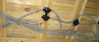
- The junction boxes are located near the wall or at the bottom, which eliminates the possibility of cable breakage.
- There is no need to chisel the walls, apply a thick layer of plaster or perform other finishing work.
Installing wires on the floor allows you to get rid of wall slitting.
Floor wiring scares people for the following reasons:
- Serious difficulties when performing repair work or when it is necessary to replace the electrical cable. Sooner or later the chain may break. It is almost impossible to find the emergency area on your own, so you will have to dismantle the system and lay a new wire. However, the problem can be avoided if you follow the rules and recommendations for installing floor wiring. For example, you should make sure that the cable placed in the pipe moves freely through it. Before pulling out the cable, tie a strong rope or wire to the far end so that you can then easily pull the new wire into the pipe.
- The cost of the work increases due to the need to purchase corrugation, which is not needed when installing in walls, when the cable is hidden inside the groove or under a thick layer of plaster.
With floor installation, replacement becomes more complicated and the cost of work increases
. There are only two disadvantages, but the first is easily eliminated if you follow the installation technology flawlessly.
DIY wiring
Modern construction trends provide for hidden wiring. It can be laid in specially made grooves in the walls - grooves. After laying and securing the cables, they are covered with putty, comparing them with the surface of the rest of the wall. If the erected walls will then be lined with sheet materials - plasterboard, gypsum plasterboard, etc., then grooves are not needed. The cables are laid in the gap between the wall and the finish, but in this case - only in corrugated sleeves. The shell with laid cables is attached with clamps to the structural elements.
How should internal wiring be laid? In a private home, when installing it yourself, you must follow all the rules
When installing, you need to remember that the internal electrical wiring of a private house is done according to all the rules and recommendations. This is the only way to guarantee safety. The basic rules are:
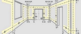
- laying wiring only vertically and horizontally, no rounded corners or beveled routes;
- all connections must be made in installation junction boxes;
- horizontal transitions must be at a height of at least 2.5 meters, from which the cable runs down to the socket or switch.
A detailed route plan, similar to the one in the photo above, must be saved. It will come in handy during repairs or wiring upgrades. You will need to check with him if somewhere nearby you need to ditch or make a hole or hammer a nail. The main task is not to get caught in the cable.
Wire connection methods
A large percentage of electrical wiring problems come from poor wire connections. They can be done in several ways:
- Twisting. Only metals that are homogeneous or do not enter into a chemical reaction can combine in this way. It is strictly forbidden to twist copper and aluminum. In other cases, the length of bare conductors must be at least 40 mm. The two wires are connected to each other as tightly as possible, the turns are laid one next to the other. The connection is wrapped on top with electrical tape and/or packed with heat-shrink tubing. If you want the contact to be 100% and losses to be minimal, do not be too lazy to solder the twist. In general, according to modern standards, this type of wire connection is considered unreliable. The rules for installing electrical wiring in a private building prohibit making twists in the walls (bricking them up)
- Connection via terminal box with screw terminals. The housing is made of heat-resistant plastic and contains metal terminals that are tightened with screws. The conductor, stripped of insulation, is inserted into the socket and secured with a screw or a screwdriver. This type of connection is the most reliable. Connecting electrical wiring using terminal boxes is fast, convenient, reliable, and safe
- Connecting blocks with springs. In these devices, contact is provided by a spring. A bare conductor is inserted into the socket and clamped by a spring.
Still, the most reliable connection methods are welding and soldering. If it is possible to make the connection like this, you can assume that you will not have problems. At least with connections.
Installing electrical wiring in a house with your own hands requires careful fulfillment of all requirements. This is a guarantee of your privacy and the safety of your private property.
After the wires from the machine to the connection point of the socket or switch are laid, they are checked for integrity with a tester - the wires are connected to each other, checking the integrity of the conductors, and each individually to the ground - checking that the insulation is not damaged anywhere. If the cable is not damaged, proceed with the installation of the socket or switch. Once connected, everything is checked again with a tester. Then they can be started on the appropriate machine. Moreover, it is advisable to sign the machine immediately: it will be easier to navigate.
After finishing the electrical wiring throughout the house and checking everything yourself, they call electrical laboratory specialists. They check the condition of the conductors and insulation, measure grounding and zero, and based on the results they give you a test report (protocol). Without it you will not be given permission to put into operation.
Some features
Returning to the first disadvantage of floor wiring, we emphasize that the specifics of installing electrical wiring of any type are clearly stated in the document PUE (“Electrical Installation Rules”). The main point is the availability of the entire system for inspection and repair work.
The points where wires connect/split must be free from mechanical tension from the material covering the floor. For this reason, various pipes made of corrugated, metal or polyethylene are used. The surface of this product takes the load of the coating. Remember that there must be enough free space inside for the wire to move.
One of the main elements of the electrical network in the house are distribution boxes. But placing them under the flooring is unrealistic, so the products are mounted in the wall. It is important to choose the correct height above the floor to avoid short circuits when the apartment is partially flooded and to prevent free access for children.
Since the corrugated pipe used for wiring must be smooth, in most cases it can be replaced with a regular polyethylene pipe with the appropriate diameter. However, the final decision is entirely up to you. Metal, corrugated and plastic products differ in technical characteristics and cost per linear meter.
PVC pipes for cable laying
On wooden floors, beams, trusses
For wood structures, wiring can be either open or hidden. Open wiring on the ceiling is performed using the same methods as on concrete structures. All installation products must be made of metal or non-flammable material.
Fastening wiring to the ceiling using insulators is used extremely rarely in modern construction, mainly to imitate an antique interior in an apartment. More often, wiring is installed in corrugated or metal hoses, which are mounted to the ceiling using clips. Often pipes are also used that are secured with clamps. The cables are pulled into pipes or sleeves fixed to the surface using steel wire.
Increasingly, plastic cable ducts are used for electrical wiring on wooden surfaces. This material does not support combustion, and the plastic is painted during production and imitates the texture of wood. Cable channels of a suitable cross-section are fixed to the ceiling surface using screws or self-tapping screws.
In places of bending, cable channels are cut at an angle. This is convenient to do using a carpenter's miter box. Special products for bending and branching are also produced. They significantly simplify the installation of electrical wiring on the ceiling. Next, the cables are placed inside and closed with snap-on covers.
When installing in plaster, cables must be secured along an asbestos strip or steel tape. Cable clamps or nail clips are used to secure cables.
It is strictly forbidden to secure the cable by nailing it between the conductors. If the wiring is installed in channels cut into the plaster, it is possible to attach the cables with a quick-drying mortar with the addition of alabaster.
When wiring under drywall, it is not necessary to cut channels, since the sheets are attached to a frame made of metal profiles. It is imperative, when laying behind suspended ceilings, to place the cables inside metal pipes, which make it possible to localize a wiring fire in the event of a short circuit. It is allowed to use steel water and gas pipes or copper.
The diameter of the pipes must ensure the installation of the required number of cables of the required size. Before use, pipes are inspected and crumpled ones are rejected. Next, they are cut into pieces of the required length and threads are cut into the ends of the steel pipes. It is imperative to remove nicks and burrs that can damage the cable insulation.
Pipe sections are connected to each other with angles or couplings. Copper pipes are bent using special pipe benders.
It should be noted that when installing any type of wiring in an apartment, it is necessary to provide for the possibility of replacing it due to physical wear and tear or an emergency. Properly performed electrical wiring installation work will ensure long-term and safe operation of the entire building or structure.
Places where it is advantageous to lay wiring under the floor
This method of wiring electrical cables is relevant in “bare” residential or administrative buildings without ready-made repairs. We are talking about various new buildings that are handed over in draft form. This approach eliminates wall slitting; the wire can be placed freely on any area of the floor with convenient wiring to sockets and switches.
The floor layout fits perfectly into wooden structures. This option completely eliminates the disadvantage associated with difficult cable accessibility. The method is more relevant than ever, since when installing electrical wiring on the walls, you have to either attach cable ducts to them, which spoils the interior of the room, or decorate everything in a retro style, which leads to significant financial costs. By hiding the cable in a wooden floor, you can take it out from under the boards at any time and perform the necessary manipulations.
Electrical installation in a wooden house
Wiring plan
Let's say you have an apartment in a new building, which still needs to be renovated before you move in.
- Typically, repairs consist of several stages:
- redevelopment (if necessary);
- plumbing work;
- pre-installation of air conditioning routes;
- construction work – plastering, installation of ceilings;
- installation of plumbing products - washbasins, showers, toilets;
- electrical wiring;
- installation of doors, floor coverings;
- wallpapering, painting;
- installation of electrical installation products - sockets, switches, and lamps.
Electrical work in an apartment is usually done first. Before starting electrical work, it is advisable to have a wiring plan. In the simplest version, it can be done by hand on a sheet of paper.
Drawing a wiring plan
So, you consulted with your household and made your decision. Now all the ideas and plans need to be transferred to paper. We draw a plan of your premises. How to do it? Let's take a standard one-room apartment as an illustrative example.
- To complete the scheme we need:
- notebook sheet;
- ruler;
- pen;
- colored pencils or markers.
The diagram shows the location of the walls and doorways. No specific dimensions are required, just a general picture.
An example of an apartment wiring plan
- The diagram should show the following elements in as much detail as possible:
- Sockets. They can be located in any convenient place, but no less than 15–20 cm from door and window openings, as well as 40 cm away from heat and gas pipelines. As for the quantity, it is customary to install one socket for every 6 m2 of area .
- Lighting. Standard layouts are designed for one large lamp in the center of the ceiling. But you can, if you wish, make additional light sources (spotlights, sconces, night lights), providing wiring for them.
- Switches. Usually they are mounted on the right side of the doorway and at a distance of 60 or 150 cm from the floor.
- Cable routes. When indicating them on your drawing, remember that the wiring must run strictly vertically or horizontally. No zigzags are allowed. If you plan to lay wires inside walls, then you should retreat 15–20 cm from ceilings and openings.
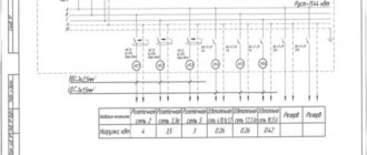
- Distribution boxes. They also need to be shown on the plan because they are where all the major cable connections are made. A box is placed on each branch from the main line, but no more than one per room.
- Distribution panel. Typically, power cabinets are installed outside the apartment in a common corridor. But some layouts are designed for internal placement of the shield, in which case the task will be a little simpler.
Marking
One way or another, between drawing up the plan and starting the rough work, there will be a procedure called “marking”.
In scientific language, marking is the operation of applying lines (scores) to the surface of the workpiece, which, according to the drawing, determine the contours of the part or place to be processed.
At the initial stages of work on distributing electricity in a room, markings are made as follows:
- first of all, the locations of sockets and switches, as well as the locations of cable outlets for household appliances, are marked on the walls;
- Next, lines are drawn along which the walls will be chipped;
- locations for distribution boxes are determined;
- the location where the apartment electrical panel will be installed is selected;
- after this, the routes of cable routes from the electrical distribution panel to a specific electrical point are marked.
In most cases, changes in the electrical wiring diagram of an apartment are easier to make at the initial stage of work, namely at the marking stage. In this case, time and financial resources will be saved, since possible changes will entail additional costs.
Advantages of corrugation
The need to place a corrugated metal or plastic pipe in the floor is due to safety reasons. It does not matter whether the electrical wiring will be hidden under a concrete screed or wooden boards. In the second case, there is only one way out - the use of a metal hose, which is associated with an increased level of fire danger.
You can avoid using corrugation if the wires are embedded in concrete, but remember: if necessary, they cannot be pulled out from under the floor. The same cannot be said about the corrugation, which allows you to freely remove the old cable and just as conveniently pull in a new one. In the future, there will be no need to destroy the floor or place wiring in other places.
Using corrugated cables to lay wires on the floor
Important Rules
Laying scheme for heated floors.
- At the points of connection, connection and branching of cable cores and wires, a supply of cable (wire) must be provided, which ensures the possibility of reconnection, connection and branching.
- Termination, connection and branching of conductors of wires and cables must be carried out using crimping, soldering, welding or clamping (bolt, screw, etc.) in accordance with the approved instructions that are currently in force.
- At branch and junction points, cables and wires should not experience any mechanical tension.
- Places for branching and connecting cores of cables and wires, connecting and branch clamps, etc. must have insulation that is equivalent to the insulation of the cores of entire sections of cables and wires.
- The electrical wiring of pipes in the premises must be replaced: hidden in the channels of building structures, and in electrical baseboards, boxes, etc. - open.
- In underground spaces, technical floors, attics, unheated basements, ventilation chambers, and especially damp rooms, electrical wiring must be installed openly.
- In buildings with building structures made of non-combustible materials, monolithic, permanent installation of group networks in the grooves of partitions, walls, ceilings, in the floor preparation layer, under plaster, in the voids of building structures can be allowed, which is carried out with cable or insulated wires in a protective sheath .
Safe installation
Before installing the cable, make sure it is intact. Special distribution boxes are used for each individual section. Avoid any twists that reduce the reliability of the system as a whole. The boxes described above are placed on the walls at a safe height to prevent moisture from entering during flooding or interference from children. In some cases, the selected height may be minimal.
The installation box can be installed directly in the floor. In this case, it should be protected by a durable removable lid that can be easily removed so that, if necessary, the master can access the contents. Don’t forget about the possibility of creating a floor wiring diagram, which will make it easier to find the right node or wire in the future.
Junction box in the floor
Another important condition for increasing the safety level of electrical wiring is the correct filling of the corrugation. Do not try to cram a lot of wires inside such a tube. It is advisable to leave about 60% of the total tube space empty. The maximum length of one line (from the distribution panel to the socket or switch) should not exceed 20 m. When placing at right angles, make sure that there are no more than two cables. However, the recommendation is similar for situations with sharper angles. Try to avoid any sharp bends.
In wooden houses, placing wires along joists is unacceptable. Installation is carried out using pre-drilled technical holes. When using wooden parts, they must be treated with a high-quality composition that prevents combustion. Avoid branching the route directly from the panel, this will significantly complicate repair work if the electrical wiring is damaged.
Laying wires in the technological holes of the log
Electrical wiring diagram above a suspended ceiling for spotlights
Typically, there are two schemes for switching on spotlights and, accordingly, two types of wiring - parallel and star. A parallel wiring diagram above a suspended ceiling is also called a loop and provides for parallel joining of all lamps, with conductor connections in the lamp itself or next to it.
The “star” circuit is a connection of conductors at one point, and the installation to each lamp is carried out with a separate cable.
The choice of wiring diagram should, in theory, be based on the convenience of wiring and maintenance of the entire circuit. But when working with spotlights, there is a peculiarity - different operating voltages of future lamps - 12 V or 220 V. As you know, according to Ohm’s law, with the same power, voltage and current are inversely proportional. In simple terms, a small current and a large voltage in one case, or a large current and a small voltage in another.
Choosing a wire for electrical wiring above a suspended ceiling
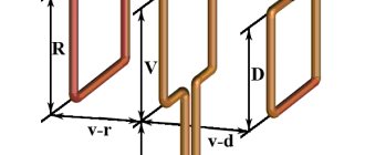
Before buying a cable for electrical wiring behind a suspended ceiling, you need to calculate the required cross-section of conductors, which directly depends on the number and power of the installed lamps. For example, we plan to install a suspended ceiling in one room with a chandelier and lighting around the perimeter of eight lamps. Typically, a recessed spotlight on suspended ceilings has a power of 35-50 W. This means that the total maximum possible power of a circuit of eight lamps is 400 Watts.
Let's consider a parallel wiring diagram. If lamps with a voltage of 220 V are used, we will get a total current of 400 Watt/220V = 1.8181 A. This means that the cross-section of the wire for such a garland should be about 10 times smaller - at least 0.1818 sq. mm. When using 12-volt lamps, we get a current of 400 Watt/12V = 33.3333 A and, accordingly, a cross-section of 3.33 square meters. mm!
But no one lays such a powerful cable; usually for lighting wiring they use a wire with a cross-section of 1.5 mm. The long-term permissible current from the PUE for a copper conductor with a cross-section of 1.5 mm2 is 19A. To correct the situation, you need to use a thin cable to deliver 220 V from the lighting box under the ceiling to the transformer or, better, two transformers. And from each transformer, connect 12-volt lamps with a thick wire along the ceiling. You can also carry out wiring for an operating voltage of 220 V and low current, and install your own low-power mini-transformer for each lamp.
Let's consider a star connection diagram in two stages: from the mounting box to the star connection point, and from the connection point to each luminaire.
For a voltage of 220V, the “box-star” section has a current of 400 W / 220 V = 1.8181 A. The section of each of the eight “star-luminaire” lamps operates at a current of 50 W / 220V = 0.2273 A. According to the calculation results, based on section with maximum current, the cross-section of the wires must be more than 0.18 square meters. mm. From the standard range of cables produced, with a double reserve, a wire with a cross-section of 0.5...0.75 sq.m. is theoretically suitable. mm.
For a voltage of 12V, the “box-star” section current is 400W / 12V = 33.33. The star-lamp section operates at a current of 50W / 12V = 4.1667 A, which is exactly equal to an eighth of the total current. For eight star-lamp sections, a cable with a cross-section of at least 0.5 sq. mm is suitable. But what to do with the “box-star” section? Strictly speaking, the lighting box contains 220V voltage. Only after the transformer do we deal with 12V and powerful current. The solution is on the surface: connect a thin 220V wire from the box to the transformer under the ceiling, and after that, from the connection point, distribute 12V with thick wires to each lamp. Or you can, similar to a parallel connection, wire everything with a thin wire under 220V, and install a mini-transformer on each lamp or use a lamp with a built-in transformer.
From all of the above, an unambiguous conclusion follows. Before you begin installing electrical wiring above a suspended ceiling, you need to know exactly which lamps will be used. The considered case is somewhat exaggerated and serves as an illustration of the problem that can be encountered when designing electrical wiring for spotlights.
For lighting wiring, in the vast majority of cases, a cable with a core cross-section of 1.5 square meters is used. mm type VVGng or stranded wire with a total cross-section of 0.75 sq. mm. PVS type. If you have these two tools, you can estimate the current load of the circuit and determine where you need to place one or more transformers.
Location in screed
The electrical cable can be hidden in the floor screed. Immerse it to a depth of at least 30 mm. If it is necessary to intersect two routes, they should be placed one above the other, which will lead to an increase in the thickness of the concrete screed. Therefore, experts recommend avoiding such situations.
Before pouring the screed, check the integrity of the cable line and make sure there is no short circuit. If there are no breaks, proceed with the installation of the covering, and then proceed to installing electrical points: switches, lighting fixtures and sockets.
Laying cables in a corrugated floor screed
If you follow the rules and recommendations, you can easily create a safe electrical network, which will be equally easy to repair if necessary. The order in which the work is performed is not so important: you can place the corrugation, and then stretch the wire through it, or install everything at once.
Electrical on the ceiling or on the floor? — Archproject
When starting an apartment renovation, many people wonder how to lay electrical cables along the ceiling, floor or walls. In this article we will talk about the pros and cons of all options.
When wiring electrical lines to the ceiling in an apartment, there is essentially only one way - using suspended ceilings. At the same time, you get all the pros and cons of suspended ceilings. The main disadvantage is the reduction in ceiling height. The advantage of electricians under a suspended ceiling is the hypothetical opportunity to redo the electrical system with a relatively small investment (you only need to make grooves on the walls, replace the suspended ceiling and wallpaper on the walls).
Attention! If you are laying electrical wiring above a suspended ceiling, do not trust plastic “corrugated” holders; secure with additional wire or ties. Is it worth putting up with the reduced volume of the room every day for the sake of a hypothetical opportunity to make an additional outlet in ten years? It’s up to you to decide
But sometimes there are simply no other options, now you will understand why
Whether for the sake of the hypothetical opportunity to make an additional outlet in ten years, it’s worth putting up with the reduced volume of the room every day, it’s up to you to decide. But sometimes there are simply no other options, now you will understand why.
Electrician for floor
Electrical wiring on the floor means that the wires will be laid in the floor screed, in other words, the wires are first laid and then filled with cement. From our point of view, this is the best option, because... in this case, firstly, less wire is wasted, because the majority of consumers are located closer to the floor (sockets). Secondly, the height of the room does not decrease. Thirdly, you don’t have to use a fairly delicate stretch ceiling.
But sometimes, during renovations, the floors are not replaced or the screed is not poured, then the only options left are wiring on the ceiling or on the walls.
Electrical on walls
This is the worst option. If possible, you should try to refuse it. There are several reasons for this. Firstly, you will have to make a fairly large number of “grooves” (holes in the wall for laying cables). Secondly, after a while you will forget where the wires go, and there is a good chance that if you decide to hang a picture on the wall, you will damage the wire. Thirdly, it is better not to touch the load-bearing walls again.
General Tips
- Do not make wire connections in a floor screed or above a suspended ceiling. All connections of electrical wires must be made in “junction” boxes, which must be located in the walls.
- Take a photo, or better yet, make a plan of the wire routes and save these photos. It is possible that in 10 years they will help you avoid repairs.
- Try to foresee all possible furniture placement options in advance and place sockets in these places. Remodeling is much more expensive than doing everything at once. In addition, the price of sockets will simply be lost against the general background of the repair.
The Archproekt company has been renovating apartments for many years. Call!
Subtleties of laying cables in a floor screed
Let's consider certain nuances associated with laying an electrical cable under a concrete screed.
Marking and diagram
The first stage of the work is applying markings. Make a decision regarding the location of the corrugation into which the cable is threaded. Do not forget about other elements of the system, which can be both in the floor and on the wall. Then transfer the resulting diagram onto paper, noting the location of each cable, which may be useful later when you have to drill the floor to install parquet boards. Thanks to an accurate diagram, you will avoid damage to the cable. Be sure to note the dimensions of the wire used and the distance at which the route is from the wall. If you have accurate data, then indicate the depth of the laying in the concrete screed.
Floor electrical wiring diagram
The marking will also simplify the further installation of socket boxes associated with gating the walls for wiring. The work will be done much more accurately, the structural elements will be distributed evenly. And in general, it will be possible to assess in advance how convenient the current location of electrical points is.
Laying electrical wiring in the floor
When installing the electrical cable, you should pay attention to its fixation. Fastening is carried out using plastic clamps, which avoids any shifts during installation of the screed. If you ignore this point, it is more likely that the wiring will simply move out of place, making the previously created diagram irrelevant. You may not even know about it, and in the worst case, you will realize it when you accidentally drill into the cable. To increase the strength of the screed and protect the corrugated pipe, experts recommend using reinforcement or mesh made of polymers.
You should not save money and purchase low-quality cable channels. Make sure to choose durable products that will improve the reliability of your home's electrical wiring. Electrical installation components must be routed from the distribution panel. Ideally, each wire should have a separate channel, since a large number of branches will complicate the potential replacement of the damaged section. This may lead to the need to open up the floor.
When you pass the cable through the channels, the created passages should be covered with plaster. It can be replaced with cement mixture or plaster. Next, a floor screed with a thickness of at least 30 mm is performed. The load on the box should be minimal to avoid deformation and destruction of the surface with subsequent damage to the wiring.
In addition to saving on materials, electrical wiring in the floor provides freedom when arranging furniture in the room. Think in advance about the location of sockets depending on where the household appliances will be located. Try to create the required number of plugs to eliminate the need for tees and extensions. It is always better to connect each device to a separate point.
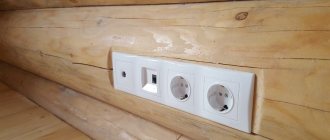
Floor socket device
As you can see, installing electrical wiring in the floor is much simpler than installing wires in the walls. However, there are some nuances and the need for impeccable implementation of the rules and recommendations prescribed in the PUE. If you doubt the quality of the work performed, contact professional specialists. A qualified electrician will install reliable wiring, drawing up its diagram in advance and calculating the amount of materials and equipment (making an estimate).
Is it possible to do the work yourself?
The option of arranging electrical wiring on the floor is not the simplest, but it is the most convenient for self-installation. You can do this kind of work with your own hands, but you don’t always use the method of laying it on the floor, since the wires are often pulled far from the panel.
In order to decide whether to use this method and how to implement it, it is necessary to consider each stage of the work in more detail.
Having determined the advantages for yourself, it is easy to make a choice in favor of the method.
Connecting a cable-type floor heating system
Connection diagram for cable heated floor
To connect a cable heated floor, you need to level the surface. Next, attach a damper tape along the wall and then lay thermal insulation. The cable can also be installed on an old surface, without a lining. The only condition for this is the presence of a heated room below. Before laying the cable, you need to stretch all the wires to connect to the thermostat.
Next, you can lay the heating element, having previously placed a regular mounting tape on the floor. This is done to keep the cable in the desired position and not move. The cable can be laid in any shape, the main thing is that it does not intersect with itself. The most effective and convenient installation method is the so-called “snake” - the cables are sold in rolls, already laid in the form of a coil on a mesh.
Connection diagrams for single-core and double-core cables for heated floors
Having distributed the cable evenly, you can secure it. It is important that the edges do not reach about 10 cm from the location of the furniture or walls. Next, you need to install a temperature sensor, which is hidden in the tube mentioned earlier. Its location should be at a distance of 40-50 cm from the edge of the heating element coil.
This completes the installation of the cable and sensor. Using a tester, you need to check the resistance of the heating element. It must correspond to the passport data. Next, you need to fill everything with screed and wait until it hardens. You cannot immediately turn on the heated floor to dry it, as cracks will appear and the strength indicator will significantly decrease. All that remains is to simply connect all the wires to the thermostat and check the functionality of the system.
thermostat for heated floors
HDPE pipe for cable: selection criteria
The main criterion when choosing HDPE pipes for cables is the throughput of the product. The value of the internal diameter of the pipe must correspond to the total cross-sectional area of the cable products that will be laid in its internal cavity. According to GOST, technical HDPE pipe is produced with a diameter of 16-225 mm with a wall thickness of 2-30 mm. Products with a cross section of up to 90 mm are produced in coils of 100 or 200 mm. Larger diameter pipes are manufactured in 12 m long sections.
On a note ! No more than 4 cables can be installed simultaneously in one HDPE pipe.
HDPE pipe with a probe for cable pulling.
The next important criterion is the strength of the product. Pipes with a small value are used for laying cables inside the building, and with a large value - underground. You can calculate the strength indicator yourself by determining the SDR parameter. To do this, it is necessary to calculate the ratio of the outer diameter to the pipe wall thickness. The lower this indicator, the higher the strength characteristics of the pipe.
Each factory product is marked with a marking that identifies the characteristics of the pipe, such as the name of the manufacturer, material of manufacture, SDR parameter, diameter, wall thickness, operating pressure, production standard, purpose and date of manufacture.