Frequency converters are technical devices that convert input network parameters into output parameters at various frequencies. Modern AC inverters have a wide frequency range.
The asynchronous frequency converter is designed to convert mains 3- or 1-phase alternating current f 50 Hz into 3-phase or 1-phase f 1 - 800 Hz.
Manufacturers produce electro-induction frequency generators, which are of the following design:
- asynchronous electric motor;
- inverters.
Frequency generators are often used to smoothly regulate the rotation speed of an asynchronous motor (IM) by generating specified network parameters at the output of the frequency generator. In the simplest cases, adjustment of f and U is performed with the corresponding V/f relationship; in more sophisticated inverters it is implemented as vector control.
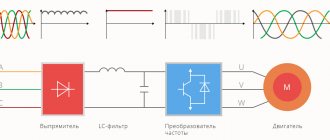
An electronic frequency converter is a construct that consists of elements:
- rectifier converting I into Iconst;
- an inverter that converts Iconst into I with the required frequency and amplitude.
Output thyristors (transistors) serve to provide the necessary current to power the motor.
For correction Uout. Another time, a choke is placed between the frequency converter and the electric motor, and a filter is installed to reduce interference.
Classification of frequency converters
According to the type of supply voltage, frequency converters are divided into types:
- single-phase;
- three-phase;
- high-voltage devices.
The main task of a frequency converter can be formulated as follows: transferring the working process to an economical mode by controlling the speed and torque of the motor, according to the specified technical parameters and the nature of the load.
In this case, the digital display of the device shows such system operating parameters as:
- the value of I and U of the engine;
- output values of frequency, speed, power and torque (f, v, P and M);
- displaying the status of discrete inputs for regulating the speed of rotation of the IM shaft and remote control of the system;
- duration of operation of the frequency converter itself.
According to the area of use, the types of inverters are:
- industrial use with power up to 315 kW;
- Inverter with vector control with power up to 500 kW;
- for controlling mechanisms with pump-fan type load (P 15 - 315 kW);
- frequencies for cranes and other lifting structures;
- for use in explosive environments;
- VFDs installed directly on the electric motor.
Drive operating voltage
An important issue will be the supply voltage. The most common case is when the power supply is from a 3-phase network producing 380 volts. There are options when the drive is designed to operate from a single phase of 220 volts. The latter option is limited to powers up to 4 kW. There are options for operating the drive at high voltage, which provide vector control of powerful motors, with power in megawatts, with lower current. All options are used for different types of solutions and depend on the nature of the electrical energy supply and on determining the use of a drive of a specific characteristic.
Frequency converter structure
The structure of a modern inverter is built on the principle of energy conversion and includes a power and control component. The first, as a rule, is performed on thyristors or transistors, which play the role of electric switches. The control unit is implemented on microprocessors. Using keys that open and close circuits, it allows you to quickly solve many diagnostic, protection, and control tasks.
According to the principle of operation, frequency converters are of two types:
- with the presence of an intermediate DC link;
- with direct connection.
All of them have a number of advantages and disadvantages that determine the scope of effective use of each of them.
Direct frequency converters
They belong to the earliest devices with a simplified power unit, which is a rectifier based on thyristors.
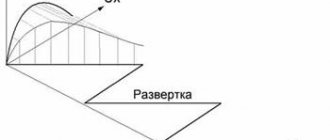
The control system turns on the group thyristors and connects the motor windings to the power supply. Direct - this is a reversible thyristor frequency generator. Its main advantage is that it connects directly to the network without additional devices.
In this way, it turns out that the U out frequency generator is formed from truncated segments of the U out sinusoids. The figure shows an example of a formed Uout for one of the load phases. 3-phase sinusoidal components Uа, Uв, Uс are supplied to the thyristor input. The voltage Uout is represented by a non-sinusoidal “sawtooth” shape, which in approximated form looks like a sinusoid (thick curve). The drawing shows that the frequency U out cannot be equal to or exceed the power supply frequency. Therefore, the control range of the electric motor rotation speed is small (less than 1: 10). Limiting limits do not make it possible to use such frequency converters in sophisticated VFDs. The latter are designed for a wide range of indicator adjustments.
The use of thyristors increases the complexity of the control system, and therefore the cost of the frequency converter increases.
The output “truncated” sinusoid of the frequency generator is a source of high-frequency harmonics, causing additional losses in the electric motor, overheating of the electric machine, reduction of torque, and noise in the power supply network that interferes with operation. The use of compensating devices increases the price, weight, size, and reduces the efficiency of the entire system.
Nevertheless, direct frequency converters delight users with their certain advantages. These include:
- sufficiently high efficiency achieved by one conversion of electricity;
- operation in various modes, including with energy recovery into the network;
- reliability, relative cheapness, complete controllability and convenience;
- availability of unlimited capacity expansion of the system;
Such circuits are used in electric drives produced in previous years. In new designs they are not developed in practice.
Frequency selection criteria
In practice, the PWM frequency can be set by the user, usually in the range from 1 to 15 kilohertz. In order to obtain a voltage more or less close to a sinusoidal shape, the PWM frequency should be 20-30 times the maximum output frequency that you want to obtain.
You can choose the PWM frequency arbitrarily for your specific task. There are several parameters that determine the choice.
Fig.7. Parameters influencing the choice of PWM frequency
1. Cable length to motor. The longer the cable, the lower the PWM frequency can be set. For example, if your cable length is 100 meters or more, then there is no point in setting the PWM frequency to more than 2.3 kilohertz, otherwise there will be large losses and wasted power at this length.
2. Acoustic engine noise. When the motor is powered by a frequency converter, extraneous noise is heard. It depends exactly on the PWM frequency that you set. The higher it is, the higher the pitch of the sound. If the purity is set to more than 8.10 kilohertz, the noise is practically inaudible. At lower frequencies (1.3.5 kilohertz) this noise is significant and causes discomfort.
3. Maximum output frequency. Most motors use a maximum inverter output frequency of 50Hz, so here the PWM frequency must be at least 20 times higher. Here you can set the frequency of 1, 2, 3, 5 kilohertz from the entire range.
If you are using a high-speed motor, for example a 400-Hz motor, then you should not set the PWM frequency to 1.3.5 kilohertz: the output will not be a sinusoid. For such high-speed motors, the PWM frequency is selected as high as possible for a given inverter, say, 15 kilohertz.
4. Heat generation from the inverter part of the converter. This is due to the fact that the IGBT transistors that generate the output voltage are not ideal and are subject to heating during operation. In order to effectively remove heat, it is necessary to use appropriate radiators and cooling fans. The greater the heat generation in this inverter part, the more powerful cooling devices must be used.
Frequency converters with DC link
These are devices made using a transistor or thyristor circuit. However, their main distinguishing feature is that the correct and safe operation of the frequency generator requires the presence of a constant voltage link. Therefore, to connect them to an industrial network, a rectifier is required. Typically, complete equipment is used, consisting of a frequency converter and rectifier, controlled by one control system.
The inverter of this group uses a two-stage conversion of electricity: sinusoidal U input with f = const is straightened in the rectifier (V), filtered by a filter (F), smoothed, and then re-converted by the inverter (I) into U ̴. Due to the two-stage conversion of electricity, the efficiency decreases and the weight and size indicators slightly deteriorate in comparison with frequency converters with direct coupling.
To create a sinusoidal U ̴ self-controlled frequency converters. They use an advanced thyristor and transistor base as the key base.
The main advantage of thyristor converter equipment is the ability to operate with large network parameters, while withstanding continuous load and pulsed influences. The devices have higher efficiency.
Frequency converters based on thyristors today are superior to other high-voltage drives, the power of which amounts to tens of MW with U out from 3 to 10 kV and more. However, their price is correspondingly the highest.
Advantages:
- highest efficiency;
- possibility of use in powerful drives;
- reasonable cost, despite the introduction of additional elements.
Intermediate chain
The intermediate circuit acts as a kind of storage facility from which the electric motor receives energy through the inverter. Depending on the combination of inverter and rectifier, the intermediate circuit can have one of the following formations:
- Inverter power supply. In this case, the intermediate circuit contains a powerful inductive coil, which converts the rectifier voltage into a varying direct current. The motor voltage itself is determined by the load. This type of circuit can only work with controlled rectifiers.
- Inverters are voltage sources. In this case, a filter is used in the intermediate circuit, which includes a capacitor. It smoothes out the voltage coming from the rectifier. Such circuits can work with any type of rectifier.
- Circuit of varying direct voltage. In this case, a breaker is installed in front of the filter, which contains transistors that switches off and on the voltage supply from the rectifier. In this case, the filter smooths out the rectangular voltages after the chopper, and also maintains a constant voltage at a given frequency.
Operating principle of the frequency converter
The fundamental drive is determined by a double conversion inverter. The principle of operation is to:
- input variable toxinusoidal type 380 or 220V is rectified by a block of diodes;
- then filtered by capacitors to minimize voltage ripple;
- then the voltage is supplied to microcircuits and transistor bridges, which create a 3-phase wave from it with set parameters;
- At the output, rectangular pulses are converted into sinusoidal voltage.
How to connect and configure a frequency converter?
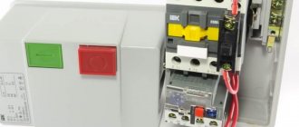
The general connection diagram for an asynchronous electric motor using a frequency converter is, in principle, not complicated, since all the main wiring is contained in the device housings. For a techie with practical knowledge, understanding it will not be difficult. In the circuit, a place is allocated for the converter immediately after the circuit breaker with a rated current equal to the rating of the electric motor. When installing the converter into a 3-phase network, it is necessary to use a three-pole circuit breaker that has a common lever. In case of overload, this will allow you to instantly disconnect all phases from the power supply network. The operating current must be equal to the current of one phase of the electric motor. For single-phase power supply, you should choose a circuit breaker with triple the current value of one phase.
In all cases, the inverter must be installed with circuit breakers connected to the neutral or ground wire.
In practice, setting up a frequency converter means connecting the cable cores to the visible contacts of the electric motor. The specific connection is determined by the nature of the voltage generated directly by the frequency converter. For 3-phase networks at industrial facilities, the electric motor is connected in a “star” - this circuit implies a parallel connection of the winding wires. For domestic use in single-phase networks, a “triangle” circuit is used (where U out does not exceed U nom by more than 50%).
The control panel must be located where it will be comfortable to use. The connection diagram for the remote control is usually shown in the user manual for the frequency converter. Before installation, before power is applied, the lever must be moved to the “off” position. After this, the corresponding indicator light should light up. By default, to start the device you need to press the “RUN” key. To smoothly increase the speed of the electric motor, you need to slowly turn the remote control handle. When rotating in reverse, you must reset the mode using the reverse button. Now you can move the handle to the working position and set the required rotation speed. It is worth noting that the control panels of individual inverters indicate not the mechanical speed, but the frequency of the supply voltage.
Variable drive configuration
The frequency converter is formed from three components:
- A controlled or uncontrolled rectifier responsible for generating the DC (direct current) voltage supplied from the power supply.
- A filter (in the form of a capacitor) that provides additional voltage smoothing.
- An inverter that simulates the voltage of the desired frequency.
Self-connection of the converter
Before you start connecting the device, you should use a de-energizing circuit breaker; it will ensure that the entire system is turned off in the event of a short circuit to any of the phases.
There are two schemes for connecting an electric motor to a frequency converter:
- "Triangle".
The diagram is relevant if you need to control a single-phase drive. The power level of the converter in the circuit is up to three kilowatts, and no power is lost.
- "Star".
A method suitable for connecting the terminals of three-phase frequency drives powered by industrial three-phase networks.
The figure shows the connection diagram for the 8400 Vector.
To limit the starting current and reduce the starting torque when starting an electric motor with a power exceeding 5 kW, star-delta switching is used.
When voltage is applied to the stator, the device is connected as a star. As soon as the motor speed begins to correspond to the nominal value, power is supplied according to the “triangle” circuit. But this technique is used only when technical capabilities allow connecting in two circuits.
In a combined star and delta circuit, sharp current surges are observed. When switching to the second type of connection, the rotational speed readings decrease significantly. To restore the previous operating mode and speed, the current should be increased.
Frequency generators are most actively used in the design of an electric motor with a power level of 0.4 - 7.5 kW.
DIY frequency converter assembly
Simultaneously with the industrial production of frequency converters, assembling such a device with your own hands remains relevant. This is especially facilitated by the relative simplicity of the process. As a result of the inverter's operation, one phase is converted into three.
The use of electric motors equipped with a similar device in domestic conditions does not cause any additional difficulties. Therefore, you can safely get down to business.
The figure shows a block diagram of frequency converters with a DC link.
The frequency converter circuits used during assembly consist of a rectifier unit, filter elements (responsible for cutting off the alternating current component and constructed from IGBT transistors). In terms of cost, purchasing individual components of the converter and doing the assembly yourself is cheaper than purchasing a finished device.
Self-assembled frequency converters can be used in electric motors with a power of 0.1 - 0.75 kW.
At the same time, modern factory frequency generators have expanded functionality, improved algorithms and improved control over the safety of the work process due to the fact that microcontrollers are used in their production.
Areas of application of converters:
- Mechanical engineering;
- Textile industry;
- Fuel and energy complexes;
- Borehole and sewage pumps;
- Automation of process control.
The cost of electric motors is directly dependent on whether it is equipped with converters.
Frequency classification
There are several types of inverters based on the size and type of power supply:
- single-phase;
- three-phase;
- high voltage units.
Semiconductor frequency converters convert the current or voltage of an industrial network. The output parameters of the required signal are freely regulated by the control elements.
Why do you need a frequency converter?
The use of gate valves and control valves in production is gradually becoming a thing of the past. The asynchronous motors that replaced them are distinguished by their high performance and power, but they are also not without characteristic disadvantages. For example, control over the speed of rotation of the rotor requires additional elements. Starting currents exceed the rated currents up to seven times. Such shock overload affects the service life of the unit.
The highly economical operation of pumps is based on constant adjustment of technical indicators such as temperature, pressure and water flow. Optimizing the operation of smoke exhausters and fans requires adjusting the temperature, air pressure and gas rarefaction. The economical use of machines is provided by adjusting the engine rotation speed. In the conveyor specificity of work, an important feature is productivity. Special frequency units are designed to solve such problems.
For companies and enterprises, private converters are necessary in terms of:
- saving energy resources;
- long service life of the mechanical and electrical parts of process equipment;
- reducing cash costs for planned repair and maintenance procedures;
- conducting operational management, fundamental control over technical parameters, etc.
The use of a frequency drive also increases the technical efficiency of production by freeing up some equipment.
VFD Application Industries
The list of industries is extensive; it is more difficult to find an industry where emergency situations are not applied:
Oil production and refining
: pumping equipment, drive of air cooling units (ACU) and cooling towers, comprehensive automation of various technological lines.
Metallurgy
: drives of roller tables, conveyors, rolling mills, winding devices of drawing mills, pumps, fans.
Mechanical engineering
: drive of processing machines, pumps, conveyor lines, printing machines.
Mining and processing production
: crushers, mixers, conveyors, sand and pulp pumps.
Chemical industry
: pumps, mixers, granulators, extruders, centrifuges, smoke exhaust and fan drives, automated control systems.
Food industry
: granulators, extruders, mills, crushers, cutters, pulp presses, labeling machines, conveyors, production lines, pumps, fans.
Housing and communal services
: various pumping equipment, automated control systems.
Construction complex
: cranes, lifting mechanisms.
Transport
: ship drive, electric transport.
Where are frequency converters used?
The equipment is widely used in industrial applications and devices where it is necessary to change the motor rotation speed, measures to combat amplitude starting currents or adjustments in control parts (combinations of elementary converters using feedback), etc. Let's consider their use as needed:
Pumps. Since power consumption is proportional, as is known, to the cube of the rotation speed, the use of a frequency converter allows saving energy consumption by up to 60%, in comparison with the method of power regulation using dampers on the pipe. The annual use of the frequency converter pays for all the costs of its purchase. The devices also allow:
- reduce heat and water losses by 5 - 10%,
- reduce the number of pipeline accidents;
- provide complete protection of the electric motor.
An additional advantage is the solution to the problem with water hammer: working inverters smooth out the start/stop of the pump. At modernized pumping stations, systems have been installed that allow pumps to be controlled in a group manner without the need to install a controller.
Fans. Everything said above for pumps also applies to fans. As for the savings in electricity consumption, they are even more significant here, since in order to directly start large fans, more powerful motor units are often used. Improvement of technological installations leads to increased profitability of production. Efficiency is also achieved by reducing idle losses.
Transporters. Adaptation of the movement speed to the speed of the technological system, which is not a constant value. A smooth start significantly increases the service life of the mechanical part of the system, since shock loads damage technical equipment.
The scope of use of frequency converters is quite extensive. Among controllable pump-type inverters of small power, we can also distinguish centrifugal pumps, compressors, centrifuges, blowers, etc.
The general industrial series of medium-power VFD-controlled frequency generators includes motors in fans, smoke exhausters, water supply systems, mixers, dispensers, and production lines.
It is difficult to imagine elevator and other lifting and transport equipment with significant overloads during start/stop without vector control using converters.
The use of an inverter with feedback makes it possible to ensure the accuracy of the rotation speed, which will be the key to improving the quality of the technological process and solving assigned problems. Well-known manufacturers have a number of models focused on operating mode in a closed system. The equipment is recommended for use in the woodworking industry, robotics, precision positioning systems, etc.
All of the listed equipment can be controlled using converters with analog-to-digital inputs/outputs for regulation, remote control and monitoring via a serial communication line.
Controller
The elevator inverter never works without an upper level controller. The controller receives signals from the user's keyboard (control panel), from sensors, limit switches and other controls. After processing the received commands, it issues control signals to the frequency converter - Start, Stop, speed change signals.
The frequency converter is an important part of elevator equipment, ensuring the comfort and safety of using the elevator. The inverter cannot be considered separately, since its selection and configuration is influenced by the electrical and mechanical parameters of other components of the elevator system.
Other useful materials:
Cascade pump control Setting up a soft starter Cooling the frequency converter
Other advantages of frequency drivers:
- smooth regulation of engine rotation speed makes it possible not to use gearboxes, variators, chokes and other control equipment, which makes the control structure simpler, cheaper and significantly more reliable;
- frequency drives combined with IM can be completely used to replace DC electric drives;
- it is possible to create multifunctional drive control systems based on an inverter with a controller;
- modernization of the technological structure can be carried out without interruption in work.
Control range
If the speed does not drop below 10% of the rated range, then any converter can be used. In other cases, you need to make sure whether the rated series converter can operate with the engine at low speeds. The asynchronous motor cools itself with a built-in fan on the shaft. As the speed decreases, cooling deteriorates. Many vector mode control converters have built-in temperature control options via a sensor.
