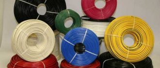
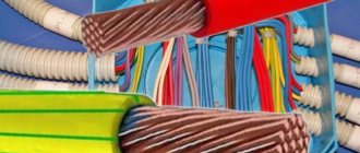
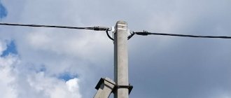
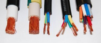
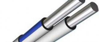
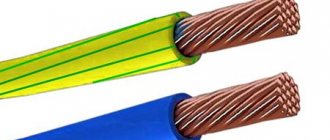
In this article you can find out all the technical characteristics of a self-supporting insulated wire (SIP-2), as well as familiarize yourself with the details necessary for its installation.
Self-supporting insulated wire (SIP) is used mainly to supply consumers with electricity generated by 10/0.4 kV substations. It traces its history back to the distant 60s of the last century, when people thought about the need to create an alternative to wires without insulation (AC and AC wires).
Self-supporting insulated wire
In groups
Insulated wires - Insulated wires for overhead lines - SIP produced by JSC Kamkabel
on RusCable.Ru: - all brands of Kamsky Cable LLC - page of Kamsky Cable LLC
General information from RusCable.Ru
according to the SIP-2 brand
SIP-2 from other manufacturers
Saranskkabel
Tomskkabel
"MOSKABELMET"
"Cable
TU 16.K71-268-98
Fittings for SIP-2
1. The carrier neutral is clamped into anchor wedge clamps (the insulation is not removed). During installation, the cable is located inside a clamp made of aluminum alloy and fixed with plastic wedges (Fig. A). Types of clamps: RA-1000, RA-1500, RA-2000.
2. Prefabricated support clamps PS-16/95 and intermediate suspension kit ES-1500, made of weather-resistant plastic, are designed for hanging wires on corner and intermediate supports (Fig. B). Together with galvanized steel brackets, they form supporting units.
3. Connecting clamps brand MJPT and MJPT-N (for neutral).
Application area
Self-supporting insulated wires (SIP) are intended for use in overhead power lines (power lines) suspended on supports or facades of buildings and structures.
Climatic modification - UHL, placement categories - 1, 2 and 3, in atmospheres of type II and III according to GOST 15150-69.
As a result of generalizing domestic experience in the construction and operation in a number of regions of the country of overhead power lines with a voltage of 0.38 kV with self-supporting insulated wires, the technical and economic advantages of these lines were revealed in comparison with overhead power lines of 0.38 kV with uninsulated wires.
Based on the positive experience of using self-supporting insulated wires in power systems, the RAO UES of Russia directive document No. OB-5145 dated June 26, 2000 “On the use of self-supporting insulated wires in construction and reconstruction” was issued.
The resistance of a SIP wire is greater than that of a regular wire, is this true?
Self-supporting insulated wire “SIP” is a stranded wire
for overhead power lines, containing insulated conductors and a supporting element intended for fastening or hanging the wire. They are used primarily for internal networks.
To compare resistance , we will need data from several tables below.
Table 1. Active resistance of current-carrying cores of insulated wires of brands SIP-1, SIP-2, SIP-4 at 90 degrees C.
Table 2. Inductive resistance of the current-carrying cores of insulated wires of the SIP-1, SIP-2, SIP-4 brands.
Table 3. Characteristics of current-carrying conductors of steel-aluminum wires and wires made of aluminum alloy with a steel core.
Table 4. Active and reactance of current-carrying conductors of wires used in cables.
For a comparative analysis, we will take aluminum wires the SIP4 4x16 and AC 16/2.7 brands . Both wires have the same useful cross-section of 16 squares (sq. mm.).
-Self-supporting insulated wire brand SIP4 4x16 is usually used for installation of overhead lines of power and lighting electrical networks designed for voltages up to 1 kV. and is used for transmission and distribution of electrical energy.
In such wires, the possibility of a short circuit is excluded, which ensures uninterrupted power supply and high reliability. This also reduces the cost of possible emergency work to restore power lines. The possibility of ice formation on the wires is excluded.
-The wire for overhead power lines of the AC brand is a stranded aluminum wire with a core of galvanized steel wires.
Received the greatest distribution. There is an outdated designation: AC grade wire with an aluminum/steel ratio of about 6, for example - AC400 = AC400/64.
The active resistance of the conductor of the SIP4 4x16 wire is 2.448 Ohms per 1 km. wire length (Table 1).
The active resistance of the conductor of the AC 16/2.7 wire is 1.8 Ohms per 1 km. wire length (Table 3).
The resistance of the current-carrying cores of SIP wires is greater than that of AC 16/2.7 wires.
Let's compare the inductive reactance of wire SIP4 4x16 (Table 2) - 0.0821 Ohm/km, and wires with a core cross-section of 16 squares used in cables (Table 4) - 0.068 Ohm/km.
The resistance of the SIP wire is higher than that of a regular one
The conductor resistance is determined by the formula:
The different resistance of conductors with a constant length L and cross-section S depends on the resistivity of the conductor p.
And the specific resistance of the conductor p , guided by
a basic concept of electrical engineering materials science, is determined by the properties of the conductor material, regardless of its length and shape in general.
The resistivity p of chemically pure aluminum is 0.028. Its change depends on the presence of impurities in aluminum.
For electrical purposes, aluminum containing no more than 0.5% impurities, grade A1, is used. Additives of Ni, Si, Zn or Fe at a content of 0.5% reduce the electrical conductivity of aluminum by 2-3%. Impurities of Cu, Ag and Mg, at the same mass content, reduce the electrical conductivity of aluminum by 5-10%. Ti and Mn greatly reduce the electrical conductivity of aluminum.
It turns out that the technology for producing aluminum for SIP wires differs from AC wires and conventional wires for cables.
A slight increase in the resistance of the current-carrying cores of SIP wires can be explained by the fact that other operational characteristics of these wires have improved.
Self-supporting insulated wires have been used in Russian power supply systems for more than 10 years, and the length of distribution networks using self-supporting insulated wires is thousands of kilometers. The operating experience accumulated over the years shows the undeniable advantages of insulated wires over non-insulated wires of grade A and AC.
I wish you success! May the skill be with you!
Advantages of SIP
- With equal capital investments, power lines with self-supporting insulated wires require lower operating costs;
- Reducing the width of clearings to be cut down during the construction of power lines in forest areas;
- Possibility of joint suspension on supports of wires with different voltage levels and with telephone lines;
- The possibility of installing power lines along the facades of buildings, which can eliminate the installation of some of the supports that clutter the sidewalks, it is possible to lay a completely or partially hidden network, making it easier to connect branches to buildings;
- Reducing safe distances to buildings and other engineering structures (electrical, telephone, overhead lines);
- Height above ground level - 4 meters, for bare wires - 6 meters;
- The possibility of a short circuit between phase wires or to ground is excluded;
- Eliminating the risk of fires if wires fall to the ground;
- High service safety - no risk of injury when touching live phase wires;
- Less weight and longer duration of snow sticking, increased reliability in areas of intense ice formation, reduction of ice and wind loads on supports;
- Reduced voltage drop due to low reactance;
- Reducing the volume of emergency recovery work;
- Ease of repair, especially when working under voltage;
- Reducing the likelihood of electricity theft and destruction of power lines;
- Safety of work near power lines.
At the customer's request, SIP-2 wire can be supplied with additional insulated conductors with a cross-section of 16 or 25 mm2 for connecting lighting circuits.
Positive qualities of SIP-2
- Can be used on common supports near other wires;
- Reduced cost of use;
- In case of unintended contacts with live phase conductors, it is safe;
- The line works even if the wires are jammed;
- When a current-carrying wire comes into contact with grounded elements, short circuit is excluded;
- Simplicity of design, you can increase the distance between supports;
- Difficulty of unauthorized connection;
- No need to replace insulators;
- You can make repairs without disconnecting the line voltage;
- The inductive reactance is 2.5-3 times lower due to insulation, unlike the AC wire.
Specifications
| Parameter | Meaning |
| Rated alternating voltage frequency 50 Hz, kV | 1,0 |
| Operating temperature of the core, no more than °C | 90 |
| Core temperature in overload mode for 8 hours, no more than °C | +130 |
| Short circuit temperature for 5 seconds, no more than °C | +250 |
| Ambient temperature, min./max., °C | -50/+50 |
| Installation at a temperature not lower than °C | -20 |
| Service life, years | 25 |
| Warranty period, years | 3 |
Resistance of current-carrying conductors, no more, Ohm/km
| cross section, sq.mm | phase | carriers |
| 16 | 1,91 | — |
| 25 | 1,20 | 1,38 |
| 35 | 0,868 | 0,986 |
| 50 | 0,641 | 0,720 |
| 54,6 | — | 0,630 |
| 70 | 0,443 | 0,493 |
| 95 | 0,320 | 0,363 |
| 120 | 0,253 | 0,288 |
| 150 | — | 0,236 |
Tensile strength of load-bearing cores, not less, kN
| cross section, sq.mm | carriers |
| 25 | 7,4 |
| 35 | 10,3 |
| 50 | 14,2 |
| 54,6 | 16,6 |
| 70 | 20,6 |
| 95 | 27,9 |
| 120 | 35,2 |
| 150 | 43,4 |
SIP installation
The basis for mounting the wire is made up of brackets; they are secured to the supports with steel mounting tape F207. All work related to the installation is mechanized. If the wire cross-section does not exceed 50 mm2, then manual rolling of SIP is permissible. A drum with a wire is installed near the support, and a rope is attached to its end. Rollers for rolling are placed at the top of the supports. During the installation process, they support the SIP, which is pulled by a rope. Laying the wire on the ground or in contact with the structure (supports) is not allowed, as this may compromise the integrity of the insulation! In the last meters of the section, the zero load-bearing core is fixed with a clamp to the final support. The load-bearing core is pulled through using a winch. The force is controlled using a dynamometer. When the wire hangs loose, it needs to be checked for sag, and then tightened completely. The zero core is secured with a clamp at the initial section, after which the winch is removed. The neutral wire is transferred from the rollers to the supporting clamps. Having finished with this, you can remove the rolling rollers. Next, the SIP line is connected with the bare ends of the wires, using crimping in the sleeve (Fig. B).
Self-supporting insulated wire is one of the best of its kind. It does not require insulators or special supports. But installation requires high-level electricians equipped with a full set of all necessary tools.
Structural and electrical parameters
| Number and cross-section of cores, pcs. x sq.mm | Estimated weight, kg/km | Diameter, mm | Permissible current load, A | One-second short circuit current, kA | |
| with aluminum alloy core | with aluminum core, reinforced with steel wire | ||||
| 1x16 + 1x25 | 135,4 | 156,7 | 15,0 | 105 | 1,5 |
| 2x16 | — | — | 14,0 | 100 | 1,5 |
| 2x25 | — | — | 17,0 | 130 | 2,3 |
| 3x16 + 1x25 | 267,4 | 288,6 | 22,0 | 100 | 1,5 |
| 4x16 + 1x25 | 333,3 | 354,6 | 26,0 | 100 | 1,5 |
| 4x16 | — | — | 22,0 | 100 | 1,5 |
| 3x25 + 1x35 | 393,2 | 426,4 | 26,0 | 130 | 2,3 |
| 4x25 + 1x35 | 491,7 | 525,0 | 26,0 | 130 | 2,3 |
| 4x25 | — | — | 26,0 | 130 | 3,2 |
| 3x25 + 1x54.6 | — | — | 26,6 | 130 | 2,3 |
| 3x35 + 1x50 | 528,7 | 571,8 | 30 | 160 | 3,2 |
| 3x35 + 1x54.6 | — | — | 28,4 | 160 | 3,2 |
| 3x50 + 1x50 | 687,5 | 730,6 | 32 | 195 | 4,6 |
| 3x50 + 1x54.6 | — | — | 32,8 | 195 | 4,6 |
| 3x50 + 1x70 | 743,1 | 805,7 | 35,0 | 195 | 4,6 |
| 3x70 + 1x54.6 | — | — | 36 | 240 | 6,5 |
| 3x70 + 1x70 | 929,0 | 991,6 | 37,0 | 240 | 6,5 |
| 3x70 + 1x95 | 998,4 | 1085,1 | 41,0 | 240 | 6,5 |
| 3x95 + 1x70 | 1186,0 | 1248,6 | 41 | 300 | 8,8 |
| 3x95 + 1x95 | 1255,4 | 1342,1 | 45,0 | 300 | 8,8 |
| 3x120 + 1x95 | 1481,6 | 1568,3 | 47,0 | 340 | 7,2 |
Calculated values of inductive reactance of SIP
| Wire size | Calculated value of the inductive reactance of the wire at a length of 1 km, Ohm | |
| Main veins | Zero load-bearing core | |
| SIP-1 | ||
| 3×16+1×25 | 0.0853 | 0.0634 |
| 3×25+1×35 | 0.0816 | 0.0615 |
| 3×35+1×50 | 0.0791 | 0.0600 |
| 3×50+1×50 | 0.0782 | 0.0604 |
| 3×50+1×70 | 0.0790 | 0.0599 |
| 3×70+1×70 | 0.0774 | 0.0600 |
| 3×70+1×95 | 0.0781 | 0.0595 |
| 3×95+1×70 | 0.0746 | 0.0595 |
| 3×95+1×95 | 0.0753 | 0.0587 |
| 3×120+1×95 | 0.0735 | 0.0584 |
| 3×150+1×95 | 0.0719 | 0.0582 |
| 3×185+1×95 | 0.0711 | 0.0590 |
| 3×240+1×95 | 0.0692 | 0.0593 |
| SIP-2 | ||
| 3×16+1×25 | 0.0865 | 0.0739 |
| 3×25+1×35 | 0.0827 | 0.0703 |
| 3×35+1×50 | 0.0802 | 0.0691 |
| 3×50+1×50 | 0.0794 | 0.0687 |
| 3×50+1×70 | 0.0799 | 0.0685 |
| 3×70+1×70 | 0.0785 | 0.0679 |
| 3×70+1×95 | 0.0789 | 0.0669 |
| 3×95+1×70 | 0.0758 | 0.0669 |
| 3×95+1×95 | 0.0762 | 0.0656 |
| 3×120+1×95 | 0.0745 | 0.0650 |
| 3×150+1×95 | 0.0730 | 0.0647 |
| 3×185+1×95 | 0.0723 | 0.0649 |
| 3×240+1×95 | 0.0705 | 0.0647 |
| SIP-4 | ||
| 2×16 | 0.0754 | — |
| 2×25 | 0.0717 | — |
| 4×16 | 0.0821 | 0.0643 |
| 4×25 | 0.0784 | 0.0621 |
| Nominal outer diameter, mm | Estimated outer diameter of the wire, mm | Estimated weight of 1 km of wire, kg |
| SIP-1 — 0.6/1 | ||
| 1×16+1×25 | 15 | 135 |
| 3×16+1×25 | 22 | 270 |
| 3×25+1×35 | 26 | 390 |
| 3×35+1×50 | 30 | 530 |
| 3×50+1×50 | 32 | 685 |
| 3×50+1×70 | 35 | 740 |
| 3×70+1×70 | 37 | 930 |
| 3×70+1×90 | 41 | 990 |
| 3×95+1×70 | 41 | 1190 |
| 3×95+1×95 | 43 | 1255 |
| 3×120+1×95 | 46 | 1480 |
| 3×150+1×95 | 48 | 1715 |
| 3×185+1×95 | 52 | 2330 |
| 3×240+1×95 | 56 | 2895 |
| SIP-2 — 0.6/1 | ||
| 3×16+1×25 | 24 | 308 |
| 3×16+1×54.6 | 28 | 427 |
| 3×25+1×35 | 27 | 424 |
| 3×25+1×54,6 | 30 | 512 |
| 3×35+1×50 | 31 | 571 |
| 3×35+1×54.6 | 32 | 606 |
| 3×50+1×50 | 34 | 727 |
| 3×50+1×54.6 | 35 | 762 |
| 3×50+1×70 | 36 | 798 |
| 3×70+1×54.6 | 39 | 973 |
| 3×70+1×70 | 40 | 1010 |
| 3×70+1×95 | 41 | 1087 |
| 3×95+1×70 | 43 | 1240 |
| 3×95+1×95 | 45 | 1319 |
| 3×120+1×95 | 48 | 1553 |
| 3×150+1×95 | 50 | 1787 |
| 3×185+1×95 | 55 | 2403 |
| 3×240+1×95 | 60 | 2968 |
| SIP-3 - 20 | ||
| 1×35 | 12 | 165 |
| 1×50 | 13 | 215 |
| 1×70 | 15 | 282 |
| 1×95 | 16 | 364 |
| 1×120 | 18 | 445 |
| 1×150 | 19 | 540 |
| 1×185 | 21 | 722 |
| 1×240 | 24 | 950 |
| SIP-3 - 35 | ||
| 1×35 | 14 | 209 |
| 1×50 | 16 | 263 |
| 1×70 | 17 | 334 |
| 1×95 | 19 | 421 |
| 1×120 | 20 | 518 |
| 1×150 | 22 | 618 |
| 1×185 | 24 | 808 |
| 1×240 | 26 | 1045 |
| SIP-4 - 0.6/1 | ||
| 2×16 | 15 | 139 |
| 4×16 | 18 | 278 |
| 2×25 | 17 | 196 |
| 4×25 | 21 | 392 |

