Due to their reliability and simplicity of design, asynchronous motors (IM) have become widespread. Most machine tools, industrial and household equipment use electric motors of this type. The rotation speed of the motor is changed mechanically (by additional load on the shaft, ballast, transmission mechanisms, gearboxes, etc.) or electrically. Electrical regulation is more complex, but also much more convenient and versatile.
For many units, electrical control is used. It provides precise and smooth control of engine starting and operation. Electrical control is achieved through:
- changes in current frequency;
- current strength;
- voltage level.
In this article we will look at popular methods of how the speed of an asynchronous motor can be adjusted at 220 and 380V.
What is an asynchronous motor?
AC electric motors have found quite wide application in various spheres of our life, in hoisting, processing, and measuring equipment. They are used to convert electrical energy that comes from the network into mechanical energy of a rotating shaft. Most often, asynchronous AC converters are used. In them, the rotation speed of the rotor and stator is different. A structural air gap is provided between these active elements.
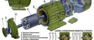
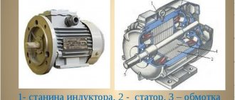
Both the stator and the rotor have a rigid core made of electrical steel (composited type, made of plates), acting as a magnetic circuit, as well as a winding that fits into the structural grooves of the core. It is the way in which the rotor winding is organized or laid out that is the key criterion for classifying these machines.
Squirrel-cage motors (SCR)
Here, a winding is used in the form of aluminum, copper or brass rods, which are inserted into the grooves of the core and closed on both sides by disks (rings). The type of connection of these elements depends on the engine power: for small values, the method of joint casting of disks and rods is used, and for large values, separate production is used, followed by welding to each other. The stator winding is connected using delta or star circuits.
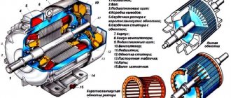
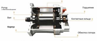
Wound rotor motors
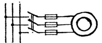
The three-phase rotor winding is connected to the network via slip rings on the main shaft and brushes. The “star” scheme is taken as the basis. The figure below shows a typical design of such an engine.
Types of devices
Triac device
The triac device is used to control lighting, power of heating elements, and rotation speed.
The controller circuit based on a triac contains a minimum of parts shown in the figure, where C1 is a capacitor, R1 is the first resistor, R2 is the second resistor.
Using a converter, power is regulated by changing the time of an open triac. If it is closed, the capacitor is charged by the load and resistors. One resistor controls the amount of current, and the second regulates the charging rate.
When the capacitor reaches the maximum voltage threshold of 12V or 24V, the switch is activated. The triac goes into the open state. When the mains voltage passes through zero, the triac is locked, and then the capacitor gives a negative charge.
Operating principle and speed of asynchronous motors
Let's consider this issue using the example of ADKR, as the most common type of electric motors in lifting, transport and processing equipment. The mains voltage is supplied to the stator winding, each of the three phases of which is geometrically displaced by 120°. After applying voltage, a magnetic field arises, which creates, by induction, an emf and a current in the rotor windings. The latter causes electromagnetic forces that cause the rotor to rotate. Another reason why all this happens, namely, EMF occurs, is the difference in the speed of the stator and rotor.
One of the key characteristics of any ADCR is the rotation speed, which can be calculated using the following relationship:
n=60f/p, rpm
where f is the frequency of the mains voltage, Hz, p is the number of stator pole pairs.
All technical characteristics are indicated on a metal plate attached to the body. But if it is missing for some reason, then the number of revolutions must be determined manually using indirect indicators. Typically, three main methods are used:
- Calculation of the number of coils. The obtained value is compared with the current standards for voltage 220 and 380V (see table below),
- Calculation of revolutions taking into account the diametric pitch of the winding. To determine, a formula of the form is used:
2p = Z1/y,
where 2p is the number of poles, Z1 is the number of slots in the stator core, y is the actual winding pitch.
Standard speed values:
- Calculation of the number of poles along the stator core. Mathematical formulas are used, which take into account the geometric parameters of the product:
2p = 0.35Z1b/h or 2p = 0.5Di/h,
where 2p is the number of poles, Z1 is the number of slots in the stator, b is the tooth width, cm, h is the back height, cm, Di is the internal diameter formed by the core teeth, cm.
After this, based on the data obtained and magnetic induction, it is necessary to determine the number of turns, which is checked against the motors’ passport data.
Making homemade relays
Making a homemade speed controller for a 12 V electric motor will not be difficult. For this work you will need the following:
- Wirewound resistors.
- Switch for several positions.
- Control unit and relay.
The use of wirewound resistors allows you to change the supply voltage and, accordingly, the engine speed. Such a regulator provides stepwise acceleration of the engine, has a simple design and can be made even by novice radio amateurs. Such simple homemade step regulators can be used with asynchronous and contact motors.
Operating principle of a homemade converter:
- Power from the network is sent to the capacitor.
- The used capacitor is fully charged.
- The load is transferred to the resistor and the bottom cable.
- The thyristor electrode connected to the positive terminal on the capacitor receives the load.
- A voltage charge is transmitted.
- The discovery of the second semiconductor occurs.
- The thyristor passes the load received from the capacitor.
- The capacitor is completely discharged, after which the half-cycle is repeated.
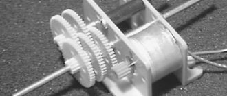
In the past, the most popular were mechanical regulators based on a variator or gear drive. However, they were not very reliable and often failed.
Homemade electronic regulators have proven themselves to be the best. They use the principle of changing step or smooth voltage, are durable, reliable, have compact dimensions and provide the ability to fine-tune the operation of the drive.
The additional use of triacs and similar devices in electronic regulator circuits allows for a smooth change in voltage power; accordingly, the electric motor will correctly gain speed, gradually reaching its maximum power.
Ways to change engine speed
Adjusting the speed of any three-phase electric motor used in lifting and transport machinery and equipment allows you to achieve the required operating modes accurately and smoothly, which is not always possible, for example, due to mechanical gearboxes. In practice, seven main methods of rotation speed correction are used, which are divided into two key areas:
- Change in the speed of the magnetic field in the stator. Achieved by frequency regulation, switching the number of pole pairs or voltage correction. It should be added that these methods are applicable to electric motors with squirrel-cage rotor,
- Changing the amount of slip. This parameter can be adjusted by using the supply voltage, connecting additional resistance to the electrical circuit of the rotor, using a valve cascade or dual power supply. Used for models with wound rotor.
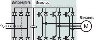
The most popular methods are voltage and frequency regulation (through the use of converters), as well as changing the number of pole pairs (implemented by organizing an additional winding with switching capability).
Voltage regulation
Speed control in this way is associated with a change in the so-called engine slip - the difference between the rotation speed of the magnetic field created by the stationary engine stator and its moving rotor:
n1— magnetic field rotation speed
n2 — rotor rotation speed
In this case, sliding energy is necessarily released - which causes the motor windings to heat up more.
This method has a small control range, approximately 2:1, and can also only be carried out downwards - that is, by reducing the supply voltage.
Typical speed controller circuits
There is a wide selection of regulators and frequency converters for asynchronous motors on the market today. However, for the domestic needs of lifting or processing equipment, it is quite possible to calculate and assemble a homemade device on a microcircuit based on thyristors or powerful transistors.
Below is an example of a circuit of a fairly powerful regulator for an asynchronous motor. Due to this, you can achieve smooth control of its operating parameters, reduce energy consumption by up to 50%, and reduce maintenance costs.
This scheme is complex. For domestic needs, it can be significantly simplified by using a triac, for example, VT138-600, as a working element. In this case, the diagram will look like this:
The motor speed will be regulated by a potentiometer, which determines the phase of the input pulse that opens the triac.
As can be judged from the information presented above, not only its operating parameters, but also the efficiency of the powered lifting or processing equipment depend on the speed of an asynchronous motor. Today you can purchase a wide variety of regulators in the retail chain, but you can also make calculations and assemble an effective device with your own hands.
Measurements
It is clear that the number of revolutions needs to be determined somehow. Tachometers are used for this. They show the rotation number at the moment. You can’t simply measure speed with a regular multimeter, except in a car.
As you can see, on electric machines you can change various parameters, adjusting them to the needs of production and household use.
DIY birthday decor
Close…
Pointed-toe cowboy bootsThe principle of operation of a homemade lock is as follows. In one half there is a permanent magnet. and in the other there is a metal plate. One of them is attached to the door. The second, with the metal plate removed, is equipped with a KEM-1 reed switch and attached to the door frame. If the door is in the closed position, the two parts of the lock are pressed, the magnet acts on the reed switch, closing its contacts. If the door opens, the magnet goes away and the reed switch contacts open.
The battery, the computer system unit, even the power supply for a laptop are all best friends. I’m already silent about such good hot water bottles as my husband and I.
Take the filler and stuff the doll. When the stuffing is completely evenly distributed, sew the product up. The handles must be sewn to the body almost near the neck.
From one pallet, sanded, impregnated and varnished, you get a garden table like a coffee table, on the left in Fig. If you have a pair in stock, you can make a wall-mounted work desk-rack out of them in literally half an hour, in the center and on the right. You can also weave chains for it yourself from soft wire, covered with a PVC tube or, better, heat-shrinkable. To fully raise the tabletop, small tools are placed on the shelf of a wall pallet.
Well, if you fill a glass bowl, vase, candy dish, punch vessel or ordinary glasses with water, scattering sea pebbles on the bottom, and let the candle-tablets float freely, you will get magical lighting for a romantic New Year. For a more interesting and unexpected effect, you can experiment with the color of the water. How are studs installed on rubber?
Handmade toys for children are beautiful, cheap and enjoyable. Every child needs original and educational toys, but it is not always possible to purchase them. Today we will show you 5 examples of fun toys that you can make yourself. They can be made from cardboard, paper or wood. In general, be inspired and make your children happy more often.
For the base of such a structure, you can use thick plywood, and for its upper part - polycarbonate. Finding solar panels online today is also not a problem.
Attention! When joining panels, do not use too much force, as you may damage the joint. This is exactly how many knives a housewife should have in her kitchen so that the cooking process is always simple and enjoyable.
This is exactly how many knives a housewife should have in her kitchen so that the cooking process is always simple and enjoyable.
To make a feeder with your own hands we will need:
Timber calculation. The boards, called staves, have biconvex sides to give the cooperage product a convexity. To make them like this, you need to take the lower part of a tree trunk and split it, similar to chopping wood. If you cut it carefully, the natural integrity of the fibers will be disrupted, which is bad for such a product. You shouldn’t start figure sawing right away - the logs need to be dried for 2 months. Moreover, dry it not under the scorching sun, but in a dark, cool room.
How to weave bracelets from laces
The fact that most New Year's costumes for preschool children are easily sewn on the basis of overalls can significantly narrow and facilitate creative search. If you learn how to sew a jumpsuit - the basis for a New Year's costume and come up with (draw from) and make decorative elements for it with your own hands, then you can make amazing and quite interesting models of New Year's outfits for children. The main thing is to think through everything in advance to the smallest detail, arm yourself with knowledge on the topic - so that the result of the work will pleasantly surprise and delight everyone.
Wardrobe design
Images
DIY birthday gift for mom photo instructions
Similar news
.
With the ever-increasing growth of automation in the domestic sector, there is a need for modern systems and devices for controlling electric motors.
Control and frequency conversion in small-power single-phase asynchronous motors, launched using capacitors, allows you to save energy and activates the energy saving mode at a new, progressive level.
Methods for controlling the speed of an IM with a wound rotor
The rotation speed of an IM with a wound rotor is changed by changing the slip. Let's look at the main options and methods.
Changing the supply voltage
This method is also used for IMs with a short-circuit rotor. The asynchronous motor is connected through an autotransformer or LATR. If you reduce the supply voltage, the engine speed will decrease.
But this mode reduces the overload capacity of the engine. This method is used for regulation within a voltage range not higher than the rated voltage, since an increase in the rated voltage will lead to failure of the electric motor.
Active resistance in the rotor circuit
When using this method, a rheostat or a set of high-power constant resistors is connected to the rotor circuit. This device is designed to smoothly increase resistance.
Slip increases in proportion to the increase in resistance, and the rotation speed of the electric motor shaft decreases.
- large range of regulation towards lower rotation speed.
- decrease in efficiency;
- increase in losses;
- deterioration of mechanical characteristics.
Asynchronous valve cascade and dual-fed machines
Changing the operating speed of asynchronous electric motors in these cases is done by changing the slip. In this case, the rotation speed of the electromagnetic field remains unchanged. Voltage is supplied directly to the stator windings. The adjustment occurs through the use of sliding power, which is transformed into the rotor circuit and forms an additional EMF. Such methods are used only in special machines and large industrial devices.