Wire PV 3 (or PV-3) is an outdated, but still used designation for PuGV wire. Its characteristics and purpose are described in GOST 6323–79, adopted in the USSR. Currently, this state standard has been cancelled, and GOST R 53768–2010 has been introduced to replace it, but the wire itself has remained virtually unchanged - except that, thanks to new technologies, it has become more flexible. Now it is called PuGV.
GOST 6323-79
Wires with copper and aluminum or aluminum-copper conductors with insulation made of polyvinyl chloride plastic for voltages up to 450 V (for networks up to 450/750 V) with a frequency of up to 400 Hz or constant voltage up to 1000 V are intended for electrical installations with stationary installation in lighting and power networks , as well as for the installation of electrical equipment, machines, mechanisms and machine tools.
Type of climatic modification OM2, HL2.
The brands, names and primary areas of application of wires are given in table. 1.
Application
Thanks to a wide range of models with different cross-sections and numbers of wires in the core, PV3 is excellent for various fields of industry and the national economy. In general, the installation PV-3 is used for:
- Domestic needs - when installing electrical wiring in an apartment, garage, moving connection points, making extension cords and for other purposes.
- Industrial - for making wiring in enterprises, connecting lighting equipment, special equipment, powerful consumers, etc.
- For communication lines with an operating frequency in the network of no more than 400 Hz.
A distinctive feature of this wire is its high resistance to atmospheric and other types of influence, due to which it is also used for external installation.
Table 1
| Wire brand | Wire name | Preferred area of application |
| Automatic reclosing | Wire with aluminum or aluminum-copper core of limited flexibility (for sections up to 16 mm2 incl. - single-wire) with polyvinyl chloride insulation | For installation in steel pipes, hollow channels of building structures, on trays, etc. for installation of electrical circuits |
| PV1 | Wire with copper core of limited flexibility (for sections up to 10 mm2 incl. - single-wire) with polyvinyl chloride insulation | Same |
| PV2 | Wire with copper core of normal flexibility with polyvinyl chloride insulation | For installation of sections of electrical circuits where wire bends are possible |
| PVZ | Wire with copper core of increased flexibility, with polyvinyl chloride insulation | Same |
| PV4 | Wire with copper conductor of high flexibility with polyvinyl chloride insulation | For installation of sections of electrical circuits where frequent bending of wires is possible |
| APPV | Wire with aluminum or aluminum-copper conductors of limited flexibility (for sections up to 16 mm2 incl. - single-wire) with polyvinyl chloride insulation, flat, with a dividing base | For permanent installation |
| PPV | Wire with copper conductors of limited flexibility (for sections up to 10 mm2 incl. single-wire) with polyvinyl chloride insulation, flat, with a dividing base | Same |
Examples of wire symbols: brand PV1 with a conductor cross-section of 2.5 mm2, natural, white or gray:
Wire PV1 2.5 B GOST 6323-79; APPV brand with two cores with a cross section of 2.5 mm2: APPV wire 2×2.5 GOST 6323-79; Brands PVZ with a conductor cross-section of 2.5 mm2, transitional or mixed colors, cold-resistant design: Wire PVZ-HL 2.5 BC GOST 6323-79.
Main manufacturers
When purchasing cable and wire products, it is important to obtain specified parameters that can ensure the nominal operating conditions of the system. Otherwise, you may encounter the problem of insufficient cross-section or inappropriate climatic design, when the connected wire or cable begins to overheat and lead to a line burnout. Therefore, it is so important to purchase PV3 only from trusted manufacturers. Among the well-established factories, the following should be highlighted:
- TD Alliance Cable;
- Special cable;
- Moskabelmet;
- Interregional trade and industrial company.
If you are just going to buy PV3 wire, pay attention to the products of the above-mentioned factories. If you already have a brand of PV3 wire from some other manufacturer, and you want to use it in electrical work, it is better to check its cross-section and the quality of the insulation. You can learn how to check the cross-section of a core at home from the corresponding article on our website:.
table 2
| Brand | Number of cores | Nominal core cross-section, mm2 | Core class |
| Automatic reclosing | 1 | 2,0-16,0 25,0-120,0 | 1 2 |
| PV1 | 1 | 0,5-10,0 16,0-95,0 | 1 2 |
| PV2 | 1 | 2,0-95,0 | 2 |
| 1 | 0,5-1,5 2,0-4,0 5,0-95,0 | 2,3 or 4 4 3 | |
| PV4 | 1 | 0.5 and 0.75 1.0 and 1.5 2.5 and 4.0 6.0 and 10.0 | 5 4 or 5 5 4 or 5 |
| APPV | 2 and 3 | 2,0-6,0 | 1 |
| PPV | 2 and 3 | 0,75-4,0 | 1 |
The maximum external dimensions of wires of the PPV and APPV brands are given in table. 3, wires of the APV, PV1, PV2, PVZ and PV4 brands - in table. 4.
ACCEPTANCE RULES
3.1. The rules for acceptance of wires must comply with GOST 26445 and this standard.
3.2. Acceptance tests
3.2.1. The volume of a batch of wires is no less than 300 m and no more than 100 km.
3.2.2. The composition of the tests and the sequence of their conduct within each group must correspond to those indicated in table. 9.
Table 9
| Items | ||||
| Test group | Type of test or inspection | technical requirements | control methods | |
| GOST 6323 | GOST 6323 | GOST 26445 | ||
| C—1 | Checking the appearance | 2.4.2; 2.4.3; 2.4.6 | — | 4.2.1 |
| S-2 | Checking design dimensions | 2.4.1; 2.4.2; 2.4.3—2.4.7 | 4.2.1 | — |
| S—3 | Voltage test | 2.5.2 | 4.3.1 | — |
| C—4 | Checking the electrical resistance of current-carrying conductors | 2.5.1 | — | 4.3.1 |
| S—5 | Checking labeling and packaging | 5.2; 5.3 | — | 4.6.1 |
| S-6 | Bend strength test | 2.7.2 | 4.5.1 | — |
3.2.3. Tests for groups C-1, C-2, C-4 and C-6 are carried out sequentially on one sample, for groups C-3 and C-5 - on independent samples.
3.1—3.2.3. (Changed edition, Amendment No. 3).
3.2.4. To carry out tests in groups, selective single-stage control is used with an acceptance number C = 0.
The sample size for groups S-1, S-2, S-4 and S-5 is 5%, for group S-3 - for category EI-2 - 100%, for category EI-1 - 2%, but not less three bays or construction lengths, for group C-6 - three samples from batches.
(Changed edition, Amendment No. 3, 4).
3.3. Periodic testing
3.3.1. The composition of the tests and the sequence of their conduct within each group must correspond to those indicated in table. 10.
Table 10
| Items | ||||
| Test group | Type of test or inspection | technical requirements | control methods | |
| GOST 6323 | GOST 6323 | GOST 26445 | ||
| P—1 | AC voltage test | 2.5.3 | 4.3.2 | — |
| Checking the electrical resistance of wire insulation | 2.5.4; 2.5.5 | 4.3.3 | — | |
| Cold resistance test | 2.6.9 | 4.4.5 | — | |
| P—2 | Determination of resistance to cracking and deformation at elevated temperatures | 2.6.13 | 4.4.24 | |
| P—3 | Checking the physical and mechanical properties of insulation | 2.7.1 | — | 4.5.6 |
| I 1 -fc. | Flame retardation test | 2.6.12 | — | 4.4.21 |
3.3.2. Tests are carried out once every 12 months.
3.4. The consumer assesses the compliance of the electrical parameters of the wires with the requirements of this standard (clauses 2.5.2, 2.5.4) during incoming inspection within 12 months from the date of manufacture according to the standards established for the acceptance and delivery of wires.
3.3—3.4. (Changed edition, Amendment No. 3).
3.5, 3.6. (Excluded, Amendment No. 3).
Table 3
| Number and nominal cross-section of cores, mm2 | Maximum external dimensions, mm | Number and nominal cross-section of cores, mm2 | Maximum external dimensions, mm | ||
| thickness | width | thickness | width | ||
| 2×0,75 | 2,6 | 6,4 | 3×0,75 | 2,6 | 10,2 |
| 2×1,0 | 2,8 | 6,8 | 3×1,0 | 2,8 | 10,8 |
| 2×1,2 | 3,1 | 7,4 | 3×1,2 | 3,1 | 11,7 |
| 2×1,5 | 3,3 | 7,8 | 3×1,5 | 3,3 | 12,3 |
| 2×2,0 | 3,7 | 8,6 | 3×2,0 | 3,7 | 13,5 |
| 2×2,5 | 3,9 | 9,0 | 3×2,5 | 3,9 | 14,1 |
| 2×3,0 | 4,0 | 9,2 | 3×3,0 | 4,0 | 14,4 |
| 2×4,0 | 4,4 | 10,0 | 3×4,0 | 4,4 | 15,6 |
| 2×5,0 | 4,6 | 10,4 | 3×5,0 | 4,6 | 16,2 |
| 2×6,0 | 4,9 | 11,0 | 3×6,0 | 4,9 | 17,1 |
Table 4
| Nominal core cross-section, mm2 | Maximum outer diameter, mm, of wire grades | |||
| APV, PV1 | PV2 | PVZ | PV4 | |
| 0,5 | 2,4 | — | 2,6 | 2,6 |
| 0,75 | 2,6 | — | 2,8 | 2,8 |
| 1,0 | 2,8 | — | 3,0 | 3,0 |
| 1,2 | 3,1 | — | 3,3 | — |
| 1,5 | 3,3 | — | 3,4 | 3,5 |
| 2,0 | 3,7 | 3,7 | 3,7 | — |
| 2,5 | 3,9 | 4,2 | 4,2 | 4,2 |
| 3,0 | 4,0 | 4,4 | 4,4 | — |
| 4,0 | 4,4 | 4,8 | 4,8 | 4,8 |
| 5,0 | 4,6 | 5,2 | 5,2 | — |
| 6,0 | 4,9 | 5,4 | 6,3 | 6,3 |
| 8,0 | 5,8 | 6,3 | 7,0 | — |
| 10,0 | 6,4 | 6,8 | 7,6 | 7,6 |
| 16,0 | 8,0 | 8,0 | 8,8 | — |
| 25,0 | 9,8 | 9,8 | 11,0 | — |
| 35,0 | 11,0 | 11,0 | 12,5 | — |
| 50,0 | 13,0 | 13,0 | 14,5 | — |
| 70,0 | 15,0 | 15,0 | 17,0 | — |
| 95,0 | 17,0 | 17,0 | 19,0 | — |
| 120,0 | 19,0 | — | — | — |
Wires are made in various colors.
The coloring is solid or made by applying two longitudinal stripes on natural-colored insulation, located diametrically.
For single-core wires used only for grounding circuits, the insulation is green and yellow.
The color of continuous insulation or applied longitudinal stripes must be specified in the order and have the designations given in table. 5.
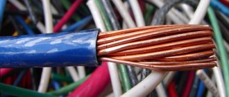
Design
Structurally, this brand of wire is a single core made of several copper wires, which is covered with a layer of polyvinyl chloride insulation. An example of the design of PV3 is shown in Figure 1:
Rice. 1: PV3 wire design
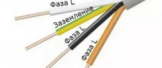
The color coding of the insulation may vary depending on the specific purpose for which the wire itself is used. For example, when installing PV3 for a PE conductor in the grounding circuit, the insulation color should be yellow-green. If PV3 is installed as a neutral conductor, then blue insulation color is selected. In practice, there is a huge selection of colors for PV3.
Rice. 2: color marking PV3
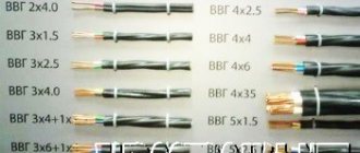
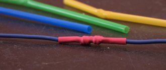
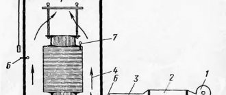
The core can use several wires of a certain cross-section, the ratio of which determines the flexibility of the entire product. The figure below shows various brands of PV, which differ in exactly this ratio:
Rice. 3: dependence of flexibility on the number of wires
The PV3 core can contain at least 7 wires; the maximum limit on their number and thickness is limited only by the manufacturer’s model range, since most often it varies up to 50 wires in the core.
Table 5
| Color | Designation |
| White, natural or gray | B |
| Yellow, orange or purple | AND |
| Red or pink | TO |
| Blue or cyan | WITH |
| Green | 3 |
| Brown | Kch |
| Black | H |
| Green-yellow | 3 -F |
If there is no indication of specific colors, the manufacturer makes the wires at his own discretion in accordance with Table. 5.
The construction length of the wires is at least 100 m. The weight of the wires is given in Tables 6 and 7.
Table 6
| Nominal core cross-section, mm2 | Estimated mass 1 km p | ewater, kg, brands | |||
| Automatic reclosing | PV1 | PV2 | PVZ | PV4 | |
| 0,5 | — | 8,5 | — | 9,0 | 10 |
| 0,75 | — | 10,5 | — | 12 | 12 |
| 1,0 | — | 13,5 | — | 14 | 15 |
| 1,2 | — | 17 | — | 18 | — |
| 1,5 | — | 20 | — | 20 | 20 |
| 2,0 | 13,5 | 26 | 28 | 28 | — |
| 2,5 | 15,5 | 30 | 31 | 31 | 31 |
| 3,0 | 18 | 38 | 41 | 38 | — |
| 4,0 | 21 | 45 | 48 | 48 | 48 |
| 5,0 | 24,5 | 55 | 62 | 62 | — |
| 6,0 | 28,5 | 65 | 69 | 70 | 70 |
| 8,0 | 39,5 | 90 | 94 | 94 | — |
| 10,0 | 47 | 108 | 116 | 116 | 120 |
| 16,0 | 66 | 172 | 177 | 182 | — |
| 25,0 | 114 | 274 | 285 | 287 | — |
| 35,0 | 146 | 366 | 370 | 378 | — |
| 50,0 | 202 | 490 | 518 | 520 | — |
| 70,0 | 266 | 695 | 705 | 730 | — |
| 95,0 | 366 | 965 | 975 | 985 | — |
| 120,0 | 422 | — | — | — | — |
Table 7
| Number and nominal cross-section of cores, mm2 | Estimated weight of 1 km of wire, kg, brand | |
| PPV | APPV | |
| 2×0,75 | 21,9 | — |
| 2×1,0 | 29,5 | — |
| 2×1,2 | 34,3 | — |
| 2×1,5 | 39,8 | — |
| 2×2,0 | 52,5 | 27,5 |
| 2×2,5 | 62 | 31,5 |
| 2×3,0 | 76 | 36,5 |
| 2×4,0 | 92,4 | 43,2 |
| 2×5,0 | — | 49,2 |
| 2×6,0 | — | 58,0 |
| 3×0,75 | 33,2 | — |
| 3×1,0 | 44,6 | — |
| 3×1,2 | 51,1 | — |
| 3×1,5 | 60,0 | — |
| 3×2,0 | 79,0 | 41,5 |
| 3×2,5 | 94,0 | 48,0 |
| 3×3,0 | 112 | 53,5 |
| 3×4,0 | 137 | 64,0 |
| 3×5,0 | — | 74,0 |
| 3×6,0 | — | 86,5 |
Electrical insulation resistance of 1 km of wire is at least 106 Ohms; for wires with the HL index - at least 8-104 Ohms.
The electrical resistance of wire insulation, measured in water at a temperature of 70 ° C, is given in table. 8.
CONTROL METHODS
4.1. Control methods must comply with GOST 26445 and this standard.
4.2. Inspection of wires for compliance with design requirements
4.1. 4.2. (Changed edition, Amendment No. 3).
4.2.1. The structural dimensions of the wires are checked according to GOST 12177. It is not allowed to determine the insulation thickness by the difference in the measured values of the outer diameters of the wire and core.
Checking the construction length of wires (clause 2.4.7) is carried out during the production process in accordance with GOST 12177.
The insulation thickness and geometric dimensions of the separate strip base can be measured during the production process with a general-purpose measuring magnifying glass in accordance with GOST 25706.
(Changed edition, Amendment No. 3, 4).
4.2.2. When checking wires for compliance with the requirement of clause 2.4.8 on a sample wire with a length of (130 ± 5) mm from one end at a distance of (25 ± 5) mm on the insulation, a circular cut is made to the core. A small portion of the insulation must be removed by hand, but the rest must not. For flat wires, this test is carried out on one of the cores.
(Changed edition, Amendment No. 4).
4.3. Inspection of wires for compliance with electrical requirements
(Changed edition, Amendment No. 3).
4.3.1. The voltage test (clause 2.5.2) is carried out in accordance with GOST 2990.
(Changed edition, Amendment No. 4).
4.3.2. The voltage test (clause 2.5.3) is carried out on samples with a length of at least 20 m in accordance with GOST 2990.
4.3.3. Measurement of electrical insulation resistance (clauses 2.5.4, 2.5.5) must be carried out after 2 hours in water on wire samples with a length of at least 5 m according to GOST 3345.
When taking measurements, the ends of wires 0.25 m long must be taken out of the water.
4.4. Inspection of wires for compliance with requirements for resistance to external influences
4.4.1. The wires are considered to have passed the tests for compliance with the requirements of paragraphs. 2.6.1—
2.6.5, 2.6.9, if after testing the samples meet the requirements of clause 2.5.2 (for the period of operation and storage).
4.4.2. The wires are considered to have passed the tests for compliance with the requirements of paragraphs. 2.6.6, 2.6.7,
2.6.10, if they meet the requirements of paragraphs. 2.5.2 and 2.5.4 (for the period of operation and storage).
4.4.3. Tests for the influence of external influencing factors should be carried out on wire samples 0.6-1.5 m long.
Before testing, samples of wires of the APV, PV1, APPV and PPV brands are wound onto a rod with a diameter equal to ten times, wires of the PV2, PVZ and PV4 brands - five times the diameter of the wire without applying a tensile load. The number of turns must be at least three.
4.4.4. The test for resistance to elevated temperatures (clause 2.6.8) is carried out according to GOST 20.57.406 (method 201-1) and GOST 25018 on insulation samples removed from wires by holding in a thermostat for 72 hours at a temperature (90± 3) °C.
After removing the samples from the thermostat, they are kept in normal climatic conditions for 1 hour; the indicator of change in tensile strength and elongation at break must be at least 0.5.
4.4.5. The test for resistance to low ambient temperatures (clause 2.6.9) is carried out according to GOST 20.57.406 (method 203-1) without electrical load.
The holding time of samples in the cold chamber is 1 hour.
After removing the samples from the cold chamber, they are kept in normal climatic conditions for 1 hour.
4.4.6. The test for the effects of mold fungi (clause 2.6.11) is carried out according to GOST 20.57.406 (method 214-1) on straightened samples with a length of at least 200 mm.
4.5. Inspection of wires for compliance with mechanical requirements
4.3.2—4.5. (Changed edition, Amendment No. 3).
4.5.1. The test for resistance to bending (clause 2.7.2) is carried out according to GOST 1579. For stranded conductors, three wires from the sample are tested.
(Changed edition, Amendment No. 4).
4.5.2. Testing of wires for compliance with the requirements of clause 2.7.3 is carried out in accordance with GOST 17491.
(Changed edition, Amendment No. 3).
4.6. Control of wires for compliance with reliability requirements
4.6.1. The service life test (clause 2.8.1) is carried out in accordance with the regulatory and technical documentation.
4.6. 4.6.1. (Introduced additionally, Amendment No. 4).
4.7—4.11. (Excluded, Amendment No. 3).
5. LABELING, PACKAGING, TRANSPORTATION AND STORAGE
5.1. Labeling, packaging, transportation and storage must comply with the requirements of GOST 26445 and this standard.
5.2. Marking
5.1, 5.2. (Changed edition, Amendment No. 3).
5.2.1. Wires must have a manufacturer's designation, which must be made in the form of continuous marking of the manufacturer's code and wire brand.
The marking may be printed, embossed or stamped onto the surface of the wire. The distance from the end of the marking to the beginning of the next one should not exceed 500 mm.
On wires of the PPV and APPV brands there should be a mark on one of the outer cores, visible without the use of magnifying devices.
It is allowed to mark wires with cross-sections from 0.5 to 6.0 mm2 inclusive in the form of a distinctive thread or colored stripes, or solid marks.
5.2.2. The label attached to the drum or drum cheek must indicate the number of segments and their length through a plus sign from the top to the bottom layers in meters.
5.2.1. 5.2.2. (Changed edition, Amendment No. 4).
5.3. Package
(Changed edition, Amendment No. 3).
5.3.1. Wires must be wound in coils or on wooden drums in accordance with GOST 5151. No more than three pieces of wire in a coil and winding of more than three pieces of wire on drums are allowed in compliance with the requirements of clause 2.4.7.
Partial covering of drums in accordance with GOST 5151 is allowed.
(Changed edition, Amendment No. 3, 4).
5.3.2. Coils of wires must be wrapped in packaging material or placed in bags or boxes, or in specialized containers for direct deliveries to the consumer, or until 01/01/92 containers that ensure the safety of wires from mechanical damage during transportation.
(Changed edition, Amendment No. 4).
5.4. Transportation and storage
5.4.1. The conditions for transporting wires in terms of exposure to climatic factors must comply with storage conditions 3 according to GOST 15150.
5.4.2. The storage conditions for wires must comply with storage conditions 3 according to GOST 15150.
5.4—5.4.2. (Changed edition, Amendment No. 3).
Table 8
| Nominal cross-section of cores, mm2 | Insulation resistance at a length of 1 km, kOhm, not less, for wire brands | ||
| APV, APPV, PPV, PV1 | PV2 | PV3, PV4 | |
| 0,5 | 15 | — | 13 |
| 0,75 | 13 | — | 11 |
| 1,0 | 11 | — | 10 |
| 1.2 | 11 | — | 10 |
| 1,5 | 11 | — | 10 |
| 2,0 | 10 | 10 | 9,0 |
| 2,5 | 10 | 10 | 9,0 |
| 3,0 | 9,0 | 9,0 | 8,0 |
| 4,0 | 9,0 | 9,0 | 7,0 |
| 5,0 | 7,7 | 7,1 | 6,5 |
| 6,0 | 7,0 | 7,0 | 6,0 |
| 8,0 | 7,0 | 6,5 | 5,6 |
| 10,0 | 7,0 | 6,5 | 5,6 |
| 16,0 | 5,0 | 5,0 | 4,6 |
| 25,0 | 5,0 | 5,0 | 4,4 |
| 35,0 | 4,0 | 4,0 | 3,8 |
| 50,0 | 4,5 | 4,5 | 3,7 |
| 70,0 | 4,0 | 4,0 | 3,2 |
| 95,0 | 4,0 | 4,0 | 3,2 |
| 120,0 | 3,2. | — | — |
The wires are resistant to sinusoidal vibration in the frequency range from 1 to 2000 Hz with an acceleration amplitude of up to 200 m-s-2.
The wires are resistant to acoustic noise in the frequency range from 50 to 10,000 Hz at a sound pressure level of up to 160 dB.
The wires are resistant to single action mechanical shock with a peak shock acceleration of 15000 m s-2 with a shock acceleration duration of 0.1-2 ms and multiple mechanical shocks with a peak shock acceleration of 1500 m s-2 with a shock acceleration duration of 1-5 ms.
The wires are resistant to linear acceleration up to 1000 m s-2.
The wires are resistant to low atmospheric pressure 5.3-104 Pa, high atmospheric pressure 29.4-104 Pa, and mold. The wires do not spread flame when laid alone.
Wires with single-wire cores are resistant to bending at an angle of ±90°. The number of cycles is at least 10 with a bending radius equal to five times the outer diameter of the wire or the thickness of the flat wires.
The long-term permissible heating temperature of the cores is no more than 70 °C.
Wires are resistant to bending at a temperature of minus 15 ° C, and wires of the PV1 and PV2 brands are also resistant to shock.
The service life of the wires is at least 15 years.
Advantages and disadvantages
Compared to other options for cable and wire products, PV3 wire has a number of significant advantages:
- The average level of flexibility - provides a fairly wide scope for the use of PV3 - can be used as an installation wire for installing electrical systems, connecting equipment, for power supply to lighting devices and various household needs.
- It has good resistance to external factors - copes well with atmospheric conditions, temperature changes, mechanical shocks, moisture, prevents the occurrence and development of mold, etc.
- The insulation contains fire retardants - substances that lead to self-extinguishing. Due to this, in the event of sparking, the PV3 wire will not light up, but will only melt. In case of exposure to open sources of fire, the insulation will also not support combustion, which ensures the possibility of its use in fire hazardous areas.
- The relatively low cost of the PV3 brand on the market, which makes it much more attractive in comparison with other wires and cables.
- Not afraid of rodents - due to treatment with repellent impregnation, it is practically not subject to destruction by pests.
Among the disadvantages of the PV3 wire, only one layer of insulation should be highlighted, which is often insufficient under certain installation conditions. In such situations, in addition to the existing dielectric, it is necessary to adapt additional corrugations, tubes or cable channels.
The second disadvantage of PV3 is the mechanical “memory” of the core itself. If you give it a shape when connecting, then after some period of operation it is extremely undesirable to twist the ends and change their position, since the wire becomes fragile.
REFERENCE DATA
GOST 6323-79 is valid indefinitely, with four amendments.
OKP codes:
| PV1 | — 35 5113 0100 | PV4 | — 35 5113 2100 |
| PV1-HL | -35 5113 2800 | PV4-HL | -35 5113 3400 |
| PV2 | -35 5113 2000 | Automatic reclosing | -35 5133 0100 |
| PV2-HL | -35 5113 3000 | APV-HL | -35 5133 0600 |
| PVZ | -35 5113 0300 | PPV | -35 5313 0100 |
| PVZ-HL | -35 5113 2900 | APPV | — 35 5333 0100. |
Manufacturers of wires of brands PV2, PV4 are given in table. 9, wires of other brands are produced by almost all cable factories.
OPERATING INSTRUCTIONS
6.1. The wires are intended for operation at ambient temperatures down to minus 50 °C and relative air humidity of 100% at a temperature of 35 °C.
Installation of wires must be carried out at a temperature not lower than minus 15 ° C.
The long-term permissible heating temperature of the cores should not exceed 70 °C.
The bending radius during installation must be at least five wire diameters for wires of the PV2, PVZ and PV4 brands and ten diameters for wires of other brands.
Sec. 6. (Changed edition, Amendment No. 3).
Table 9
| Wire brand | Manufacturing plants |
| PV2, PV2-HL | Yuzhkabel, Marposadkabel, Chuvashkabel, Armcable, Kirskabel, Expokabel, Bela-Ruskabel, Uralkabel, Sevkabel, Kavkaz-cable, Donbasskabel, Autoprovod, Andi-zhankabel, Kazakhstankabel, Kazenergoka-bel, Odeskabel, Smolkabel |
| PV4, PV4-HL | Marposadkabel, Electric wire, Podolsk cable, Kirskabel, Sibkabel, Uralkabel, Expokabel, Kamenets-Podolskkabel, Ka-zakhstankabel, Yuzhkabel, Autoprovod, Don-basskabel, Pskovkabel, Odeskabel, Kav-kazkabel, Andijankabel, Smolkabel, To-mskkabel |