Dependence of conductor resistance on temperature
Specific resistance, and therefore the resistance of metals, depends on temperature, increasing with temperature. The temperature dependence of conductor resistance is explained by the fact that
- the intensity of dispersion (number of collisions) of charge carriers increases with increasing temperature;
- their concentration changes when the conductor is heated.
Experience shows that at temperatures that are not too high and not too low, the dependences of resistivity and conductor resistance on temperature are expressed by the formulas:
ho_t = ho_0 (1 + alpha t) ,) (
R_t = R_0 (1 + alpha t) ,)
where ρ
0,
ρ
t are the specific resistances of the conductor substance at 0 °C and
t
°C, respectively;
R
0,
R
t - conductor resistance at 0 ° C and
t
° C,
α
- temperature coefficient of resistance: measured in SI in Kelvin minus the first power (K -1). For metal conductors, these formulas are applicable starting at temperatures of 140 K and above.
Temperature coefficient
The resistance of a substance characterizes the dependence of the change in resistance when heated on the type of substance. It is numerically equal to the relative change in resistance (resistivity) of the conductor when heated by 1 K.
mathcal h alpha mathcal i) - average value of the temperature coefficient of resistance in the interval Δ T
.
For all metal conductors α
> 0 and varies slightly with temperature.
For pure metals α
= 1/273 K -1.
In metals, the concentration of free charge carriers (electrons) is n
= const and the increase in
ρ
occurs due to an increase in the intensity of scattering of free electrons on ions of the crystal lattice.
For electrolyte solutions α
-1 . The resistance of electrolytes decreases with increasing temperature, since the increase in the number of free ions due to the dissociation of molecules exceeds the increase in the dispersion of ions during collisions with solvent molecules.
Formulas for dependence ρ
and
R
versus temperature for electrolytes are similar to the above formulas for metal conductors.
It should be noted that this linear dependence is preserved only in a small temperature range, in which α
= const. At large temperature ranges, the dependence of the electrolyte resistance on temperature becomes nonlinear.
Graphically, the dependences of the resistance of metal conductors and electrolytes on temperature are shown in Figures 1, a, b.
At very low temperatures, close to absolute zero (-273 °C), the resistance of many metals abruptly drops to zero. This phenomenon is called superconductivity
. The metal goes into a superconducting state.
The dependence of metal resistance on temperature is used in resistance thermometers. Usually, platinum wire is used as the thermometric body of such a thermometer, the dependence of whose resistance on temperature has been sufficiently studied.
Temperature changes are judged by changes in wire resistance, which can be measured. Such thermometers allow you to measure very low and very high temperatures when conventional liquid thermometers are unsuitable.
Series connection of conductors
Resistance when connecting conductors in series
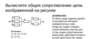
A serial connection of conductors is when we connect another conductor to one conductor and so on along the chain. This is a series connection of conductors. They can be connected to each other as many as you like.
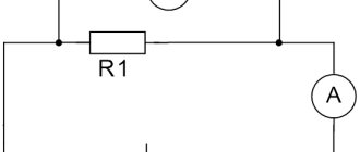
series connection of resistors
What will their total resistance be? It turns out that everything is simple. It will be equal to the sum of all the resistances of the conductors in this circuit.
It turns out that we can write that
formula for series connection of resistors
Example
We have 3 conductors that are connected in series. The resistance of the first is 3 Ohms, the second is 5 Ohms, the third is 2 Ohms. Find their total resistance in the circuit.
Solution
Rtotal = R1 + R2 + R3 = 3+5+2=10 Ohm.
That is, as you can see, we simply replaced the chain of 3 resistors with one resistor RAB.
show with a real example using a multimeter Video where these connections are described in detail:
Current strength through series connection of conductors
What will happen if we apply voltage to the ends of such a resistor? An electric current will immediately run through it, the strength of which will be calculated according to Ohm’s law I=U/R.
It turns out that if a certain current flows through the resistor RAB, therefore, if we decompose our resistor into components R1, R2, R3, it turns out that the same current flows through them as flowed through the resistor RAB.
current through series connection of conductors
It turns out that when conductors are connected in series, the current strength that flows through each conductor is the same . That is, the same current flows through resistor R1 as through resistor R2 and the same current flows through resistor R3.
Voltage when connecting conductors in series
Let's look again at a circuit with three resistors
As we already know, in a series connection, the same current flows through each resistor. But what will happen to the voltage across each resistor and how to find it?
It turns out that everything is quite simple. To do this, you need to remember Uncle Ohm's law again and simply calculate the voltage across any resistor. Let's do just that.
Let us have a circuit with these parameters.
We now know that the current strength in such a circuit will be the same everywhere. But what is its value? Here's the rub. First we need to bring this chain to this form.
It turns out that in this case RAB = R1 + R2 + R3 = 2+3+5=10 Ohm. From here we already find the current strength according to Ohm’s law I=U/R=10/10=1 Ampere.
Half the job is done. Now it remains to find out what voltage drops across each resistor. That is, we need to find the values UR1, UR2, UR3. But how to do that?
Yes, everything is the same, through Ohm's law. We know that a current of 1 Ampere passes through each resistor, we have already calculated this value. Ohm's law says I=U/R, hence we get that U=IR.
Hence,
UR1 = IR1 =1×2=2 Volts
UR2 = IR2 = 1×3=3 Volts
UR3 = IR3 =1×5=5 Volts
Now the fun begins. If you add up all the voltage drops across the resistors, you can get... the source voltage! It is equal to 10 Volts.
It turns out
U=UR1+UR2+UR3
We got the simplest voltage divider.
Conclusion: the sum of the voltage drops in a series connection is equal to the supply voltage .
Dependence of conductor resistance on temperature
Specific resistance, and therefore the resistance of metals, depends on temperature, increasing with temperature. The temperature dependence of conductor resistance is explained by the fact that
- the intensity of dispersion (number of collisions) of charge carriers increases with increasing temperature;
- their concentration changes when the conductor is heated.
Experience shows that at temperatures that are not too high and not too low, the dependences of resistivity and conductor resistance on temperature are expressed by the formulas:
ho_t = ho_0 (1 + alpha t) ,) (
R_t = R_0 (1 + alpha t) ,)
where ρ
0,
ρ
t are the specific resistances of the conductor substance at 0 °C and
t
°C, respectively;
R
0,
R
t - conductor resistance at 0 ° C and
t
° C,
α
- temperature coefficient of resistance: measured in SI in Kelvin minus the first power (K -1). For metal conductors, these formulas are applicable starting at temperatures of 140 K and above.
Temperature coefficient
The resistance of a substance characterizes the dependence of the change in resistance when heated on the type of substance. It is numerically equal to the relative change in resistance (resistivity) of the conductor when heated by 1 K.
mathcal h alpha mathcal i) - average value of the temperature coefficient of resistance in the interval Δ T
.
For all metal conductors α
> 0 and varies slightly with temperature.
For pure metals α
= 1/273 K -1.
In metals, the concentration of free charge carriers (electrons) is n
= const and the increase in
ρ
occurs due to an increase in the intensity of scattering of free electrons on ions of the crystal lattice.
For electrolyte solutions α
-1 . The resistance of electrolytes decreases with increasing temperature, since the increase in the number of free ions due to the dissociation of molecules exceeds the increase in the dispersion of ions during collisions with solvent molecules.
Formulas for dependence ρ
and
R
versus temperature for electrolytes are similar to the above formulas for metal conductors.
It should be noted that this linear dependence is preserved only in a small temperature range, in which α
= const. At large temperature ranges, the dependence of the electrolyte resistance on temperature becomes nonlinear.
Graphically, the dependences of the resistance of metal conductors and electrolytes on temperature are shown in Figures 1, a, b.
At very low temperatures, close to absolute zero (-273 °C), the resistance of many metals abruptly drops to zero. This phenomenon is called superconductivity
. The metal goes into a superconducting state.
The dependence of metal resistance on temperature is used in resistance thermometers. Usually, platinum wire is used as the thermometric body of such a thermometer, the dependence of whose resistance on temperature has been sufficiently studied.
Temperature changes are judged by changes in wire resistance, which can be measured. Such thermometers allow you to measure very low and very high temperatures when conventional liquid thermometers are unsuitable.
Low alloy steels
Low alloy steels are able to resist the passage of electricity slightly more than carbon steels. Their electrical resistivity is (20...43)·10 -8 Ohm·m at room temperature.
It should be noted that steel grades of this type are the worst conductors of electric current - these are 18Х2Н4ВА and 50С2Г. However, at high temperatures, the ability to conduct electric current among the steels listed in the table practically does not differ.
Electrical resistivity of low-alloy steels ρe·10 8 , Ohm m
| steel grade | 20 | 100 | 300 | 500 | 700 | 900 | 1100 | 1300 |
| 15HF | — | 28,1 | 42,1 | 60,6 | 83,3 | — | — | — |
| 30X | 21 | 25,9 | 41,7 | 63,6 | 93,4 | 114,5 | 120,5 | 125,1 |
| 12ХН2 | 33 | 36 | 52 | 67 | — | 112 | — | — |
| 12ХН3 | 29,6 | — | — | 67 | — | 116 | — | — |
| 20ХН3 | 24 | 29 | 46 | 66 | — | 123 | — | — |
| 30ХН3 | 26,8 | 31,7 | 46,9 | 68,1 | 98,1 | 114,8 | 120,1 | 124,6 |
| 20ХН4Ф | 36 | 41 | 56 | 72 | 102 | 118 | — | — |
| 18Х2Н4ВА | 41 | 44 | 58 | 73 | 97 | 115 | — | — |
| 30G2 | 20,8 | 25,9 | 42,1 | 64,5 | 94,6 | 114,3 | 120,2 | 125 |
| 12MH | 24,6 | 27,4 | 40,6 | 59,8 | — | — | — | — |
| 40Х3М | — | 33,1 | 48,2 | 69,5 | 96,2 | — | — | — |
| 20Х3ФВМ | — | 39,8 | 54,4 | 74,3 | 98,2 | — | — | — |
| 50S2G | 42,9 | 47 | 60,1 | 78,8 | 105,7 | 119,7 | 124,9 | 128,9 |
| 30N3 | 27,1 | 32 | 47 | 67,9 | 99,2 | 114,9 | 120,4 | 124,8 |
High alloy steels
High-alloy steels have electrical resistivity several times higher than carbon and low-alloy steels. According to the table, it can be seen that at a temperature of 20°C its value is (30...86)·10 -8 Ohm·m.
At a temperature of 1300°C, the resistance of high- and low-alloy steels becomes almost the same and does not exceed 131·10 -8 Ohm·m.
Electrical resistivity of high-alloy steels ρe·10 8 , Ohm m
| steel grade | 20 | 100 | 300 | 500 | 700 | 900 | 1100 | 1300 |
| G13 | 68,3 | 75,6 | 93,1 | 95,2 | 114,7 | 123,8 | 127 | 130,8 |
| G20H12F | 72,3 | 79,2 | 91,2 | 101,5 | 109,2 | — | — | — |
| G21X15T | — | 82,4 | 95,6 | 104,5 | 112 | 119,2 | — | — |
| Х13Н13К10 | — | 90 | 100,8 | 109,6 | 115,4 | 119,6 | — | — |
| Х19Н10К47 | — | 90,5 | 98,6 | 105,2 | 110,8 | — | — | — |
| P18 | 41,9 | 47,2 | 62,7 | 81,5 | 103,7 | 117,3 | 123,6 | 128,1 |
| EH12 | 31 | 36 | 53 | 75 | 97 | 119 | — | — |
| 40Х10С2М (EI107) | 86 | 91 | 101 | 112 | 122 | — | — | — |
Chromium-nickel austenitic steels
Chromium-nickel austenitic steels are also stainless, but due to the addition of nickel they have a resistivity almost one and a half times higher than that of chromium steels - it reaches a value of (70...90)·10 -8 Ohm·m.
Electrical resistivity of chromium-nickel stainless steels ρe·10 8 , Ohm m
| steel grade | 20 | 100 | 300 | 500 | 700 | 900 | 1100 |
| 12Х18Н9 | — | 74,3 | 89,1 | 100,1 | 109,4 | 114 | — |
| 12Х18Н9Т | 72,3 | 79,2 | 91,2 | 101,5 | 109,2 | — | — |
| 17Х18Н9 | 72 | 73,5 | 92,5 | 103 | 111,5 | 118,5 | — |
| Х18Н11Б | — | 84,6 | 97,6 | 107,8 | 115 | — | — |
| Х18Н9В | 71 | 77,6 | 91,6 | 102,6 | 111,1 | 117,1 | 122 |
| 4Х14НВ2М (ЭИ69) | 81,5 | 87,5 | 100 | 110 | 117,5 | — | — |
| 1Х14Н14В2М (ЭИ257) | — | 82,4 | 95,6 | 104,5 | 112 | 119,2 | — |
| 1x14N18M3T | — | 89 | 100 | 107,5 | 115 | — | — |
| 36Х18Н25С2 (ЭЯ3С) | — | 98,5 | 105,5 | 110 | 117,5 | — | — |
| Х13Н25М2В2 | — | 103 | 112,1 | 118,1 | 121 | — | — |
| Х7Н25 (ЭИ25) | — | — | 109 | 115 | 121 | 127 | — |
| Х2Н35 (ЭИ36) | 87,5 | 92,5 | 103 | 110 | 116 | 120,5 | — |
| H28 | 84,2 | 89,1 | 99,6 | 107,7 | 114,2 | 118,4 | 122,5 |
