Power cables play a very important role in the system of ensuring uninterrupted power supply to machines and devices. Many cable lines have a service life of several decades, which means they are subject to a higher failure rate. For this reason, it is necessary to replace worn cable lines, first of all, in the worst technical condition. But first of all, determine why the cable damage occurred.
Taking into account the above statements, it is very important to correctly assess the condition of the cable, as well as identify areas that are especially at risk of failure. A power outage can cause production losses and threats due to the lack of power supply to key facilities and the most important economic structures of a city, province or even the entire country. The above considerations make the issue of correct assessment of the technical condition of the cable line relevant. This assessment should be based on diagnostic tests that can detect and isolate defects that may soon lead to failure. It is necessary to know the mechanisms that lead to degradation of cable insulation, the effects of this aging, and location techniques to locate weak spots.
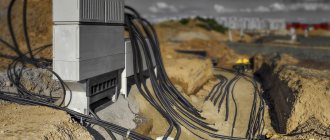
For operation in macroclimatic regions with temperate and cold climates, as well as for laying electrical communications in earthen trenches, the ASBl-6 3x150 cable is used - an armored conductor with sufficient protection from possible atmospheric, compression and mechanical influences. Taken from here: Complex supply of cable and wire products and fittings KompleksEnergo.
Cable damage - causes
The main factors causing damage to cable lines include:
- electrical factors such as overvoltages, electrical and electrostatic discharges, overloads or incorrect measurements of insulation properties;
- damage caused by improper cable manufacturing quality, mainly defects in the design of cables, cores or insulation;
- the influence of external environmental factors on the cable in use, including the influence of variable temperature and climatic conditions, dust, moisture and all chemical factors;
- damage caused by overuse, which may include degradation and aging of insulation, as well as chemical transformation processes affecting the used cable;
- atmospheric factors, such as precipitation, the general humidity of the ground on which the cable operates, wind, lightning strikes or the magnetic effects of solar storms;
- other factors such as animal and rodent infestation, cable malfunction, improper installation or mechanical damage.
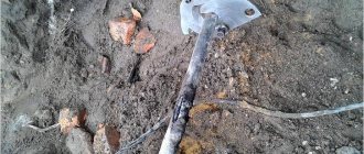
Most cable failures are caused by multiple factors acting simultaneously or sequentially. For cables operating in soil, one of the most serious damage factors is the movement of soil along the cable route, causing one part of the cable to stretch and another to be crushed.
Such movements most often occur in areas of active mining, on artificially created earthen embankments, in mountainous and high-altitude areas, as well as in seismically active areas. High stresses in the soil cause the dielectric in the cable to shear, causing insulation to break and breaking cable sleeves and other cable connections. Dielectric shifts are especially dangerous for oil-paper insulated cables.
Do RCA cables wear out over time?
RCA cables wear out for the same reasons as HDMI cables. They have exposed metal connections and the connection between the cable conduit and the plug is subject to wear. Since the plug transmits a single electrical signal, it will not be subject to signal degradation due to rust.
However, you should always replace rusty cables. Even if you don't notice a difference in audio or video quality, rust can damage your equipment.
Failure to check the box may cause your device and cable to merge. Even if they are not soldered together, rust from the cable can transfer to your device and cause rust from the inside.
What else affects damage to cable connections?
Other types of cable damage include:
- mechanical,
- electrolytic
- corrosion damage.
These types of damage cause the metal sheaths of oil-paper insulated cables to deteriorate and allow moisture to penetrate, resulting in multiple damages inside the cable as well as damage to the outer insulating coating of any type of cable.
In thermoplastic cables made of PVC or polyethylene, moisture ingress also causes damage to the sealing coating and the formation of water logs. Pitting cable insulation is formed due to erosion of the dielectric as a result of partial discharges. Such failures are characterized by high contact resistance. Voltage testing is used to detect damage early on this model.
When testing a cable, its characteristic impedance and propagation coefficient are determined. The impedance value depends on the cable type and is different for coaxial cable, installation cable, or power cable. Two cables with the same insulating material, manufactured by different manufacturers, can have different values of the same coefficient. Examples of propagation coefficient values for selected dielectric types:
- oil impregnated paper 0.50-0.56n;
- polyethylene 0.64n with foam;
- polyethylene 0.67n;
- Teflon 0.71n;
- 0.94-0.98n air.
Correct determination of the propagation coefficient is important when determining the distance to the fault. The spread coefficient depends on:
- the type of insulation used;
- cable geometry;
- cable service life.
Repair of cables and cable lines
Scheduled repair
is the repair of all cable lines not listed above, which is carried out according to a schedule approved by the management of the energy service.
The cable line repair schedule
is drawn up monthly based on entries in walk-through and inspection logs, test and measurement results, as well as data from dispatch services.
Major repairs of cable lines
are carried out according to an annual plan, developed annually in the summer for the next year based on operational data.
When drawing up a capital repair plan, the need to introduce new, more modern types of cables and cable fittings is taken into account. It is planned to repair cable structures and all work related to the serviceability of lighting, ventilation, fire-fighting equipment, water pumping devices. The need for partial replacement of cables in certain areas that limit the capacity of lines or do not meet the requirements of thermal resistance in changed operating conditions of the network with increased currents is also taken into account short circuit Repair of cable lines in operation
is carried out directly by the operating personnel themselves or by the personnel of specialized electrical installation organizations.
When repairing operating cable lines, the following preparatory work is performed - disconnecting the cable line and grounding it, reading the documentation and clarifying the brand and cross-section of the cable, issuing a safety permit, loading materials and tools, delivering the team to the work site; preparation of the workplace - making pits, excavating pits and trenches, identifying the cable to be repaired, fencing the workplace and excavation sites, identifying the cable in the distribution center (TP) or in cable structures, checking the absence of flammable and explosive gases, obtaining a permit for hot work; preparation for installation - approval of the team, puncturing the cable, cutting the cable or opening the coupling, checking the insulation for moisture, cutting off sections of damaged cable, setting up a tent; laying a repair cable insert; repair of cable couplings
- cutting of cable ends, phasing of cables, installation of couplings (or couplings and terminations);
registration of completion of work - closing the doors of switchgear, transformer substations, cable structures, handing over keys, backfilling pits and trenches, cleaning and loading tools, delivering the team to the base, drawing up an as-built sketch and making changes to the cable line documentation, report on the completion of repairs; cable line measurements and testing. In order to speed up repair work on cable lines, mechanization should be widely used when performing excavation work: pneumatic jackhammers, electric hammers, concrete breakers, excavators, means for heating frozen soil. Special mobile cable workshops are used to transport repair crews. Repairs of cable lines
can be simple, not requiring much labor and time, and complex, when the repair lasts several days. Simple repairs include, for example, repairs of external covers (jute cover, polyvinyl chloride hose) , painting and repair of armor strips, repair of metal shells, repair of end seals without dismantling the body, etc.
The listed repairs are carried out in one shift by one team (unit). Complex repairs include those when it is necessary to replace large lengths of cable in cable structures with preliminary dismantling of the cable that has failed, or to lay a new cable in the ground over a section several tens of meters long (in rare cases, hundreds of meters). Repairs are complicated in most cases by the fact that the cable route passes through complex sections with many turns, with the intersection of highways and utility lines, with a large depth of cable, and also in winter, when it is necessary to warm the ground. When performing complex repairs, a new section is laid cable (insert) and two connecting couplings are mounted. Complex repairs are carried out by one or several teams, and, if necessary, around the clock, using earth-moving mechanisms and other means of mechanization. Complex repairs are carried out either by the energy service of the enterprise (city networks), or with the involvement of specialized organizations for the installation and repair of cable lines. 2. REPAIR OF PROTECTIVE COVERS
Repair of external jute cover.
A cable stretched through pipes, blocks or other obstacles, which has stripped off the impregnated cable yarn and the remaining outer covers to the steel armor, must be restored. Repair is carried out by winding with resin tape in two layers with 50% overlap, followed by coating this area with heated bitumen mastic MB 70 ( MB 90). Repair of PVC hose and sheaths
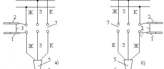
. The first method of repairing a polyvinyl chloride hose or casings is welding, which is carried out in a stream of hot air (at a temperature of 170-200 ° C) using a welding gun with electrically heated air (Fig. 1) or a gas-air gun (Fig. 2). Compressed air is supplied under pressure 0.98-104 Pa from a compressor, compressed air cylinder, portable unit with a hand pump. Fig 1. Welding gun PS-1 with electrical heating: - nozzle for hot air outlet, 2 - heating air chamber; 3 - fitting for supplying compressed air, 4 - electrical wire
A polyvinyl chloride rod with a diameter of 4-6 mm is used as a welding additive.
Before welding, areas to be repaired must be cleaned and degreased with gasoline, foreign inclusions must be cut out with a cable knife, and protruding edges and burrs in places where the hose is damaged must be cut off. To repair punctures in small holes and cavities, the damaged area in the hose or sheath and the end of the filler rod are heated for 10- 15 with a stream of hot air, then the stream is withdrawn, and the end of the rod is pressed and welded to the hose at the heating site. After cooling, making sure that the welding of the rod is strong by lightly tugging it, the rod is cut off. To seal and level the weld seam, the repair area is heated until signs of melting appear, after which a piece of cable paper folded in three or four layers is pressed onto the heated area by hand. For reliability, the operation is repeated 3-4 times. To repair a hose or shell that has cracks, slits and cutouts, the end of the filler rod is welded to the entire area of the hose at a distance of 1-2 mm from the damage site. After making sure that the welding is strong, direct the air stream so that the lower part of the filler rod and both sides of the slot or slot are simultaneously heated. By pressing lightly on the rod, the latter is laid and welded along the crack or slot. Welding of the rod is completed in its entirety at a distance of 1-2 mm from the damage. Then the protruding surfaces of the rod are cut off with a knife and the welded seam is leveled. Hose or sheath ruptures are repaired using polyvinyl chloride patches or cut cuffs. The patch is made of plastic so that its edges overlap the tear site by 1.5-2 mm. The patch is welded along the entire perimeter to the hose, and then a filler rod is welded along the resulting seam, and the protruding surfaces of the rod are cut off and the seam is leveled at the welding site. To repair a hose or sheath using a split cuff, cut off a piece of polyvinyl chloride tube 35-40 mm longer than the length of the damaged area, cut the tube lengthwise and put it on the cable symmetrically to the damaged area. The cuff is temporarily secured with polyvinyl chloride or calico tape with a pitch of 20-25 mm, the end of the rod is welded at the junction of the cuff with the hose (sheath), and then the rod is laid and welded around the end of the cuff. After welding both ends of the cuff to the hose (shell), remove the temporary fastening tapes, weld the rod along the cut of the cuff, cut off the protruding surfaces of the rod and make the final alignment of all welds. According to the second method, repair of PVC hoses and cable sheaths
can be carried out using epoxy compound and glass tape.
The surface of the hose or sheath is pre-treated as indicated above, and additionally roughness is created on it using a hog file. The place of damage and beyond its edges at a distance of 50-60 mm in both directions is lubricated with epoxy compound K-P5 or K-176 with hardeners introduced into it. Four to five layers of glass tape are applied over the layer of epoxy compound, each of which is also coated with a layer of compound. Temporary repairs of hoses and sheaths in order to prevent moisture from penetrating under the cable
sheath, as well as to prevent the leakage of bitumen composition from under the hose, can be carried out using adhesive polyvinyl chloride tape with a 50% overlap in three layers with the top layer coated with polyvinyl chloride varnish No. 1. According to the second method, temporary repairs are carried out using LETSAR tape in three layers with 50% overlap.
Painting armor tapes.
If, during inspections in cable structures on openly laid cables, damage to the armored covering of the cable is detected by corrosion, they are painted.
It is recommended to use heat-resistant pentaphthalic varnishes PF-170 or PF-171 (GOST 15907-70*) or heat-resistant oil-bitumen paint BT-577 (GOST 5631-79*). The best way to paint is to use a spray gun, or, if you don’t have one, a brush. Repair of armor tapes.
On openly laid cables, detected sections of destroyed armor tapes are cut off and removed.
Temporary bandages are made in places where the tapes are cut. Next to the temporary bands, both tapes are carefully cleaned to a metallic shine and served with POSSu 30-2 solder, after which the grounding wire is secured with bands of galvanized wire with a diameter of 1-1.4 mm and soldered with the same solder. The cross-section of the grounding conductor is selected depending on the cross-section of the cable cores, but not less than 6 mm2. When tinning and soldering armored tapes, solder fat is used. The duration of each soldering should be no more than 3 minutes. Temporary bandages are removed. An anti-corrosion coating is applied to the exposed area of the shell. In cases where mechanical impacts are possible on the cable section being repaired, one layer of armor tape is additionally wound around it, which is previously removed from the cable section with intact armor. The tape is wound with 50% overlap and secured with galvanized wire bands. In this case, the grounding conductor along the entire length of the jumper must be fluffed out in order to create a tight fit of the armor around the section of the cable
being
repaired . the damage site, at a distance of 150 mm from the damage site, the sheath is removed from the cable. The top layer of the belt insulation is removed and checked for moisture in heated paraffin.
If there is no moisture and the insulation is not destroyed, the lead or aluminum sheath is repaired. A strip 70-80 mm wider than the bare section of the cable and 30-40 mm longer than the circumference of the cable along the sheath is cut out of sheet lead 2-2.5 mm thick. Two filling holes are made in the strip so that they are located above the exposed part of the cable. The strip is thoroughly cleaned of dust and dirt with a rag soaked in gasoline. The removed semiconductive layer of paper and the top tape of the waist insulation are restored and secured with bandages made of cotton threads. The area is scalded with MP-1 cable mass. A strip of lead is wrapped around the bare part of the cable so that it extends evenly to the edges of the cable sheath
, and the edges of the resulting lead pipe overlap each other by at least 15-20 mm.
First, the longitudinal seam is soldered with POSSU 30-2 solder, and then the ends of the pipe are bent to the cable sheath and soldered to it. For cables with an aluminum sheath, in the place where the lead pipe is soldered, the cable sheath is served with grade A solder. The coupling is filled with hot cable mass MP-1. After cooling and topping up, the filling holes are sealed. A bandage of copper wire is applied to the soldered area at the ends, turn to turn with a diameter of 1 mm with an outlet of 10 mm to the cable sheath and is soldered to the sheath. The repaired area is covered with resin tape in two layers with 50% overlap. In the event that moisture has penetrated under the sheath or the belt insulation is damaged, as well as the core insulation, the section of cable is cut out along the entire length where there is moisture or damage to the insulation. Instead, a piece of cable of the required length is inserted and two connecting couplings are installed. The cross-section and voltage of the cable must correspond to the cut section. You can use a different brand of cable for insertion, but its design is similar to the cut section. 4 RESTORATION OF PAPER INSULATION OF CABLE
In cases where the current-carrying conductors are not damaged, but the core insulation and belt insulation are damaged, but there is no moisture in it, the insulation is restored, followed by installation of a split lead coupling.
The cable is excavated to such a length that it is possible to create sufficient slack in the cable to separate the cores from each other. After dividing the conductors and removing the old insulation, the insulation of the conductors is restored by applying paper rollers or LETSAR tape with pre-treatment with MP-1 scalding mass. A split lead coupling is installed and the longitudinal seam is first soldered, and then the coupling is soldered to the cable sheath. This repair can be performed on horizontal sections of cable routes, where there is no increased oil pressure, since a coupling with longitudinal soldering has less mechanical strength. 5. REPAIR OF CURRENT-CONDUCTING CABLE CONDUCTORS
If the cable cores are broken at a short length and it is possible to tighten the cable due to the “snake” made during installation, the usual repair of the connecting lead or epoxy coupling is carried out. In the event that there is no supply of cable, extended connecting sleeves can be used and couplings.
Repair in this case is carried out with one lead coupling. In all other cases, when repairing current-carrying cable cores, a cable insert is used and two lead or epoxy couplings are installed. 6. REPAIR OF CONNECTING COUPLINGS
The need
to repair the coupling
or install the cable insert and two couplings is determined after inspecting the coupling and disassembling it.
In the event that a breakdown occurs from the soldering point of the conductor or from the sleeve to the body of the lead coupling and the destruction from the breakdown is small in size and the insulation is not moistened, the coupling is sequentially disassembled and the damaged part of the insulation is disassembled. Then the insulation is restored with paper rollers or LETSAR tape and scalded with mass MP-1. The split coupling body is installed, and all further operations for assembling the coupling are performed. If a breakdown occurs in the neck of the coupling from the core to the edge of the shell and the insulation is not moistened, the coupling is disassembled. Then a section of the armor and sheath is cut to the length necessary for convenient separation of the cores. The insulation of the damaged core is restored and scalding is performed. The extended split lead coupling body is installed and all coupling installation operations are performed. If it is impossible to make an extended coupling due to large damage, then cable insertion is used with the installation of two couplings according to the technology provided for in the technical documentation. In most cases, damage to couplings occurs during preventive tests with increased voltage. And if repairs are not started immediately after determining the location of the damage, moisture begins to enter the coupling. In this case, repair of the damaged coupling is carried out by cutting out the defective coupling and cable sections. As a rule, the longer a damaged and unrepaired coupling lies in the ground, the longer the cable insertion has to be made for restoration when repairing a cable line. 7. REPAIR OF OUTDOOR INSTALLATION END COUPLINGS Outdoor installation end couplings
in most cases fail during rainy periods of the year or at high relative humidity and, as a rule, have large defects and destruction inside the coupling.
Therefore, the damaged coupling is cut off, the cable insulation is checked for moisture, and if the paper insulation is not moistened, the coupling is installed in accordance with the requirements of the technical documentation. If the cable length at the end of the line has sufficient margin, then repairs are limited to installing only the end coupling. If the cable supply is not enough, then a cable of the required length is inserted at the end of the cable line. In this case, it is necessary to install connecting and end couplings. Dismantled couplings can be used for re-installation. But to do this, it is necessary to clean the housing and all parts of the coupling from soot, wash them with gasoline and dry them. In outdoor installation end couplings
with a metal casing, check the seals and tighten the nuts once a year during the entire period of operation.
At the same time, inspect the contact connections and, if necessary, clean the contact surfaces and tighten the bolts. Systematically (as needed according to the inspection results) the soldering areas, reinforcement seams and seals are painted with XB-124 enamel. The surface of epoxy end couplings for outdoor installation must be painted with air-drying enamels EP-51 or GF-92HS during operation (once every 3-5 years, depending on local conditions). Painting is carried out in dry weather, having previously cleaned the surface of the coupling and insulators. The insulators of the end couplings of external and internal installations, as well as the insulating surfaces of the end seals, must be periodically cleaned of dust and dirt with a lint-free cloth moistened with gasoline or acetone. More frequent cleaning should exposed cable end fittings in workshops of industrial enterprises and areas with conductive dust. The frequency of wiping and cleaning of cable end fittings at a given electrical installation is established by the chief engineer of the local power company. 8. REPAIR OF END SEALS
If the termination body is destroyed and the cores in the spine burn out, repair of the terminations is carried out in the same way as the repair of end couplings, with the exception that the termination body and parts cannot be reused.
Repair of end seals
in steel funnels in case of destruction of the core insulation is carried out in the following sequence - the destroyed core insulation or has become unusable (pollution, moisture) is removed from the cores, one layer of paper insulation is wound up, winding is carried out in five layers with a 50% overlap of adhesive polyvinyl chloride tape or three layers of rubberized tape followed by coating with insulating tapes or paints.
Instead of the indicated tapes, repairs can be performed using LETSAR tape (two layers) and PVC tape (one layer). In case of cracking, peeling, partial failure and significant contamination of the filling composition, especially when these defects are accompanied by a noticeable displacement of the cores between themselves or towards the funnel body (which can in turn be caused by an incorrect position or absence of a spacer plate), the steel funnel should be completely refilled. The old filling compound is removed (melted), the funnel is lowered down and cleaned of soot and dirt. A new seal is rolled up (under the funnel), and the funnel is put in place. The neck of the funnel is wrapped with resin tape, and the funnel along with the cable is attached to the supporting structure with a clamp. The correct position of the porcelain bushings is checked. The funnel is filled with a filling compound (MB-70, MB-90). Repair of end seals made of polyvinyl chloride tapes
is carried out in the presence of an impregnating composition in the spine or on the cores, in case of cracking and breaks of the tapes.
The repair technology consists of dismantling old tapes and winding new PVC or LETSAR tapes on the cores. Repair of epoxy end seals
in case of destruction of windings on the cores is carried out with the dismantling of old tapes, restoration of new LETSAR tapes and additional filling of epoxy compound so that the tapes extend into the poured compound by at least 15 mm. When the impregnating composition flows through the cable in the root of the seal, the lower part of the seal in a section of 40-50 mm and at the same distance the section of armor or sheath (for unarmored cables) are degreased. A two-layer winding made of cotton tape lubricated with an epoxy compound is applied to the grease-free section of the termination body and the adjacent cable section 15-20 mm wide. A repair mold is installed (Fig. 3), which is filled with epoxy compound. Rice. 3. Installation of a repair form to eliminate leakage of the impregnating composition at the point where the cable enters the termination body: 1 - termination body, 2 - repair form; 3 - leak location Fig. 4. Installation of a repair form to eliminate a leak at the point where the cores exit the casing body: 1 - repair form; 2 - place of leak, 3 - seal body If the tightness at the point where the conductors exit from the seal body is broken, the upper flat part of the seal body and sections of tubes or wire windings 30 mm long adjacent to the body are degreased. A removable repair form is installed (Fig. 5 4), the dimensions of which are selected depending on the standard size of the seal. Filling the mold with the compound is done in the same way as in the previous case. If the tightness on the conductors is broken, the defective section of the tube or conductor winding is degreased and a repair is applied. two-layer winding made of cotton tapes with generous coating of each turn of the winding with epoxy compound or LETSAR tape in three layers. If the tightness at the junction of the tube or winding with the cylindrical part of the tip is broken, the surface of the bandage and the section of the tube or winding of the core with a length of 30 mm are degreased. A two-layer winding of cotton tapes is applied to the fat-free areas with a generous coating of compound on each turn of the winding. A dense bandage of twisted twine is placed on top of the winding and also coated with an epoxy compound. E.G. Ponteleev
| Cable cross-section selection table. Calculation of the cross-section of wires and cables based on current and power. |
| Cabling. Methods and rules for laying cables. |
| XLPE insulated cables: pros and cons |
Cable damage - measuring system parameters
After determining the cable parameters, the parameters of the measuring system are determined. First, the appropriate measurement range is selected, taking into account that the emitted pulse is attenuated in the cable, and its amplitude decreases as it moves away from the device. The level of damping depends on:
- cable type;
- service life;
- quality of connections.
Logging systems play an important role in the fault detection process. They are used as autonomous systems or systems equipped with automatic protection. Fault recording systems perform their role best because they can record instantaneous values of phase currents and voltages, as well as automatic protection signals associated with the operation of devices installed at both ends of a line or system device.
Thanks to the voltage and current values stored in the device's memory, the type of damage and its time course are determined. Current and voltage values are recorded moments before a fault occurs by means of a time delay device installed on the line. Thus, it is possible to determine the moment of damage and predict its development. The voltage and current values are the basis needed to calculate the distance from the fault location.
Do HDMI cables wear out over time?
Like all cables, HDMI cables can fail over time. Like any other cable, it is subject to wear and tear at the junction of the cable tube and the plug. Additionally, since the connection consists of 19 pins inside a metal shell, it is possible for it to tarnish or rust. However, you shouldn't hold on to HDMI cables for so long.
Unlike analog connections, HDMI is an evolving standard that has gone through several different versions. HDMI 2.1 was released in November 2022. Typically we expect a new version of HDMI to come out every three years.
New versions of HDMI have improved signal transmission and additional functions. This means the video and audio quality will improve over time. It could also mean that new features like consumer electronics control and eARC will be improved.
Troubleshooting Rules
Troubleshooting electrical systems is a complex job, the rules and conditions of which are contained in current legislation. In accordance with the standards of GOST, PUE, SNiP and others, electrical measurements aimed at finding problems in cable lines must be carried out in compliance with the following conditions:
- All employees of the electrical measuring team must have the required level of electrical safety and use the necessary personal protective equipment in their work.
- Testing of cable lines must take place within a predetermined time period; violation of predetermined test dates is not allowed.
- During the inspection, you should use equipment specially designed for testing electrical systems that has the required accuracy class and has passed state tests.
Depending on the time it takes specialists to detect the fault, immediately after the measurements the necessary repairs can be carried out to replace the damaged cable section. If a fault is detected, specialists will have to replace the cable by installing a new wire of 5 meters or more in length. To install the cable, you must use cable sleeves specially designed for this purpose.
Prolonged measuring work can negatively affect the functionality and reliability of the entire cable line. It is not uncommon for moisture to enter the cable duct during testing, which can subsequently lead to new malfunctions and breakdowns.
Thus, to reduce risks, search work to detect faults on a cable line is usually divided into two main stages. First, specialists will have to carry out special measurements to determine the approximate area of damage, after which the craftsmen will begin excavation work.
Do digital optical cables wear out over time?
Unlike most other types of cables, digital optical cables do not require metal in their construction. Instead of transmitting electricity through a metal wire, digital optical cables send pulses of light along a fiber optic wire.
If your digital optical cable doesn't have exposed metal parts at the connections, rust is one less thing you have to worry about. However, some manufacturers make their digital optical cables with metal connections for added durability. These connections may rust. However, if you are waiting for the connections to rust, then you are waiting too long to replace the cable.
As with all cables, the connection between the plug and the cable tube can become loose. In this case, the cable may stop working. Additionally, fiber optic cables are much more sensitive to crimping than standard wire cables. Even pinching the wire too tightly can damage the fiber optics.