VVG-P).
When ordering a cable, the following must be indicated sequentially: its designation with the necessary additions, the number and cross-section of the cores, the operating voltage in kilovolts separated by a dash. The letters “ozh” in brackets next to the core cross-section indicate the unambiguous design of the cable with monolithic cores, for example
Example: VVG-T 3x25(ozh) - 0.66 - VVG cable in tropical design with three monolithic cores with a cross-section of 25 mm2 for a voltage of 0.66 kV/
VVG cables can have from one to six cores with a cross-section from 1.5 mm2 to 240 mm2. The range of core cross-sections depending on their number and operating voltage of the cable is given in the table.
| Number of cores | Nominal cross-section, mm 2 | |
| cable 0.66 kV | 1 kV cable | |
| 1,2,3,4 | 1,5 — 50 | 1,5 — 240 |
| 5,6 | 1,5 — 25 | 1,5 — 25 |
Two-core VVG cables must have cores of the same cross-section. Three-, four- and five-core cables must have all conductors of the same cross-section or one conductor of a smaller cross-section (grounding or neutral conductor). Six-core VVG cables must have four cores of equal cross-section and two wires of smaller cross-section. The cross-sections of neutral conductors (in the case of a smaller cross-section than the main ones) and grounding conductors, depending on the cross-section of the main conductors up to 50 mm2, are given below.
| Main veins | 1,5 | 2,5 | 4 | 6 | 10 | 16 | 25 | 35 | 50 |
| Zero core | 1,5 | 1,5 | 2,5 | 4 | 6 | 10 | 16 | 16 | 25 |
| Grounding conductor | 1,0 | 1,5 | 2,5 | 2,5 | 4 | 6 | 10 | 16 | 16 |
The most common among VVG cables with conductors of unequal cross-sections are cables with three main and one neutral conductor (the so-called “three plus”).
Two- and three-core VVG cables with a cross-section up to 16 mm2 inclusive can have a flat design. In round cables, the insulated cores must be twisted, and twisting with an alternating change in direction is allowed.
Cores with a cross section of up to 50 mm2 are round in shape. Cores up to 16 mm2 are made only monolithic; over 16 mm2 can also be twisted from individual wires (number of wires: at least 7 for sections 16, 25 and 35 mm2; at least 19 for sections 50, 70 and 95 mm2).
The insulated conductors must have a distinctive color, while the insulation of the neutral conductors should be blue, and the insulation of the ground conductors should be yellow-green. Digital marking of cores is also allowed.
To increase mechanical stability in VVG cables intended for installation in the ground, the empty space between twisted insulated conductors should be filled with bundles or a mixture of insulating materials.
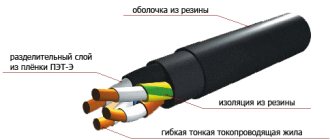
The sheath must be applied in such a way that it can be easily separated from the core insulation. To do this, a Mylar tape can be laid between the core insulation and the sheath. The shell color is predominantly black.
The nominal and minimum values of the radial insulation thickness for VVG cables with a cross-section of up to 50 mm2 for an operating voltage of 0.66 kV and 1 kV are given in the table.
| Cable voltage, kV | Nominal cross-section of cores, mm | Nominal insulation thickness, mm | Minimum insulation thickness, mm |
| 0,66 | 1 — 2,5 | 0,6 | 0,44 |
| 4 and 6 | 0,7 | 0,53 | |
| 10 and 16 | 0,9 | 0,71 | |
| 25 and 35 | 1,1 | 0,89 | |
| 50 | 1,07 | ||
| 1-2,5 | 0,8 | 0,62 | 1,3 |
| 4-16 | 1,0 | 0,8 | |
| 25 and 35 | 1,2 | 0,98 | |
| 50 | 1,4 | 1,16 |
The thickness of the sheath of VVG cables depends on the twisting diameter of the insulated cores under the sheath. The nominal and minimum values of the shell thickness are given in the table.
| Diameter under the shell, mm | Nominal insulation thickness, mm | Minimum insulation thickness, mm |
| Until 6 | 1,2 | 0,92 |
| 6 – 15 | 1,5 | 1,18 |
| 15 – 20 | 1,7 | 1,35 |
| 20 – 30 | 1,9 | 1,52 |
| 30 – 40 | 2,1 | 1,69 |
Oil-filled
- Installed in a pipeline………………………… T
- PVC hose……….. Shv
- The same with a reinforced protective layer………….………. Shvu
- The cover is asphalted…………………………..…….. A
- The same armored with round wires…….. K
- Lead sheath………………………………………….… C
- Same aluminum, corrugated aluminum. Ah, Ag
- Oil pressure is low……………………………………. N
- The same high………………………………………………………. VD
- Oil-filled (with copper core)………………… M
Distinctive features of cable and conductor
Often, in non-professional practice, the term “cable” is equated to any type of electrical wire. Meanwhile, the concepts of “cable” and “wire” should be distinguished. And, first of all, the separation involves the factor of transmitted power.
A cable is a product whose structure combines at least three conductors in insulation, additionally protected inside the shell with a special material - parchment, rubber, lead, etc.
Wire is a product consisting of one, maximum five conductors (cord), in the latter case, united by a common casing.
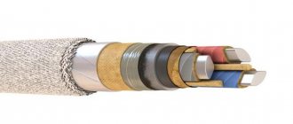
Classic power cable structure: 5 – protective sheath of the assembly; 4 – armored layer; 3 – common shell of current-carrying metal conductors; 2 – insulation of the conductors themselves; 1 – metal conductor
The priority use of cables is industrial and economic facilities. Wires are actively used in everyday life, as well as in other areas.
Separately, bare wires that do not have insulation should be highlighted. The main use of such products is in the installation of centralized power lines.
With paper insulation and viscous impregnation
- Improved…………………………………… ..U
- Without outer cover………………………………………………………. G
- Type of cover………………………………………………………. B, Bl, B2l, Bn, Mon, K, ShV, ShPS
- Lead sheath…………………………………………… C
- Same aluminum…………………………………………. A
- Insulated cores together……………………………–
- The same separately…………………………………………………… Oh
- Copper vein………………………………………………………–
- The same aluminum……………………………………………. A
- Ordinary insulation…………………………………….–
- The same impregnated with a non-draining composition………….. C
Structural basis of the cable product
The design of the cable or electrical wires determines the technical and operational characteristics of the product. Actually, the design of cable or wire products is, in most design variations, a fairly simple technological approach.
Classic version:
- Cable insulation.
- Core insulation.
- Metal core – solid/bundled.
A metal core is the base of a cable/wire through which electric current flows. The main characteristic, in this case, is the throughput, determined by the cross-section of the core. This parameter is influenced by the structure - solid or bunched.
Such a property as flexibility also depends on the structure. In terms of the degree of “softness” of bending, stranded (bundled) conductors are characterized by better properties than single-core wires.
The structural design of the current-carrying part is traditionally represented by “beam” or “solid” (monolithic). This has implications, for example, in relation to flexibility properties. The picture shows stranded/bundled wire type
The cores of cables and wires in electrical practice, as a rule, have a cylindrical shape. At the same time, it is rare, but there are several modified shapes: square, oval.
The main materials for the manufacture of conductive metal cores are copper and aluminum. However, electrical practice does not exclude conductors whose structure contains steel cores, for example, a “field” wire.
While a single electrical wire is traditionally built on a single conductor, a cable is a product where several such conductors are concentrated.
With plastic insulation
- PVC hose……….. Shv
- Without outer cover………………………………………………………. G
- Armored…………………………………………………. BB
- Self-extinguishing polyethylene sheath
- and vulcanized polyethylene,
- polyvinyl chloride plastic, aluminum……… P, Ps, Pv, V, A
- Copper vein………………………………………………………–
- The same aluminum……………………………………………. A
Currently, as a rule, cables with aluminum conductors in an aluminum sheath are used. The use of cables with copper conductors requires special justification. For cable lines laid in ground and water, armored cables are used. The use of lead-sheathed cables is intended for laying underwater lines, in mines hazardous for gas and dust, for laying in particularly dangerous corrosive environments. In other cases, if it is impossible to use cables in aluminum or plastic sheaths, their replacement with cables in lead sheaths requires special justification.
In recent years, cables with cross-linked polyethylene insulation (Russian designation XLPE, English designation XLPE) have become widespread in the networks of foreign power systems. Medium voltage cables made of cross-linked polyethylene occupy 80–85% of the market in the USA and Canada, 95% in Germany and Denmark, 100% in Japan, Finland, Sweden and France.
The main advantages of cables with XLPE insulation:
- manufactured for voltages up to 500 kV;
- cable service life is at least 30 years;
- the carrying capacity, depending on the installation conditions, is 15–30% higher than that of cables with paper or oil-filled insulation, because cables with XLPE insulation are designed for long-term operation at a core temperature of 90 °C, and their paper-oil analogues allow heating up to 70 °C;
- meet environmental requirements;
- laying and installation are less dependent on the weather and can be carried out even at a temperature of –20 ° C;
- Maintenance and repair become much cheaper and easier. In the event of mechanical damage, the laying and installation of couplings and end seals in the field is much easier.
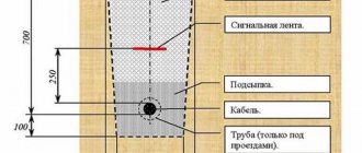
For cables with normally impregnated paper insulation, the maximum permissible level difference between laying points is given in Table. 3.27. The difference in levels for cables with non-drip impregnation, plastic and rubber insulation is not limited. The maximum possible level difference in oil-filled low-pressure cable lines is 20–25 m. For high-pressure cables (in steel pipes), the possible level difference between stop couplings is determined by the minimum permissible reduction in oil pressure in the pipeline to 1.2 MPa. Normal oil pressure is assumed to be (1.5±2%) MPa, the maximum is agreed with the manufacturer.
The maximum construction lengths of power cables are given in table. 3.28. For oil-filled cables of 110 kV and above, the standard construction length is up to 800 m. The manufacturer specifies the construction lengths of such cables in accordance with the line laying project. Design data for paper-insulated cables up to 35 kV and oil-filled cables 110 and 220 kV with plastic insulation are given in Table. 3.29 and 3.30.
Wire design
The wire can consist of one or several cores, it can be either bare or with insulation. The wire strands are laid parallel to each other and twisted into a bundle. Power copper wire is often found as part of indoor electrical lines, and bare versions are used to transmit energy to power lines and laid over the air.
The wire design resembles a cable one, but here everything is much simpler.
Conductor
Performs the function of conducting current. Basic requirements: minimal heating, flexibility, resistance to corrosion, good electrical conductivity and low cost. The core of the flexible power wire is made in the form of a wire made of aluminum or copper, which is characterized by classes from 1 to 6. The higher the level, the better the product can withstand bending load.
Basic cable types
Table 3.23
| Insulation | Execution |
| Rubber and plastic | Three-core with plastic insulation, lightweight for agricultural electrification 10 kV Three-core and single-core 6-35 kV Single-core 110-220 kV |
| Paper | With viscous impregnation:
Oil filled:
|
VVG power cable load currents
Permissible load currents for cables with a cross-section of up to 50 mm2 laid in air are indicated in the table.
| Nominal cross-section of cores, mm2 | Permissible load current, A | ||
| With two main cores | With three main cores | With four main cores | |
| 1,5 | 24 | 21 | 19 |
| 2,5 | 33 | 28 | 26 |
| 4 | 44 | 37 | 34 |
| 6 | 56 | 49 | 45 |
| 10 | 76 | 66 | 61 |
| 16 | 101 | 87 | 81 |
| 25 | 134 | 115 | 107 |
| 35 | 166 | 141 | 131 |
| 50 | 208 | 177 | 165 |
Standard cross-sections of single-core oil-filled cables 110-500 kV
Table 3.24
| Cable brand | Voltage, kV | Section, mm2 |
| Low pressure: MNS, MNAShv, MNAgShVkh MNSA, MNAShv, MNAgShvu MNAShvu, MNSK | 110 | 120, 150, 185, 240, (270) 300, (350), 400, 500, (550), 625, 800 |
| MNSA, MNSHv, MNAgShvu, MNAShvu, MNSC | 220 | 300, (350), 400, 500, (550), 625, 800 |
| High pressure MVDT | 110 | 120, 150, 185, 240, (270), 300, 400, 500, (550), 625, 700 |
| 220 | 300, 400, 500, (550), 625, 700, 1200 | |
| 330 | 400, 500, (550), 625, 700 | |
| 500 | (550), 625, 700, 1200 |
Note: cables with cross-sections indicated in brackets are manufactured in agreement with the manufacturer.
Requirements for marking power cable VVG
On the sheath no more than every 300 mm the distinctive index of the manufacturer and the year of manufacture of the cable must be applied. For cables with a diameter under the sheath of less than 20 mm, the use of colored marking thread is allowed.
The drum cheek or label attached to the coil or drum must indicate:
— trademark of the manufacturer; — symbol of the cable (full indicating the number of cores and cross-section); — cable length in meters and number of segments; — gross or net weight when delivered in coils in kilograms; — date of manufacture (year, month); — drum or coil number.
The label must bear a technical control stamp and a certification mark.
Standard sections of paper-insulated cables, mm2
Table 3.25
| Cables with cores | Voltage, kV | |||||
| copper | aluminum | 6,10 | 20 | 35 | ||
| with normally impregnated insulation | ||||||
| — | AASU, AAShvU, AAShpu, AAShpsU | 10-240 | — | 120-400** | ||
| SPU, SPLU, SblU, SB2lu, SBnU, SBGU, SGU, SBU, SKLU | AABlu, AAB2lu, ASPU, ASPLU, ASBU, ASBGU, ASGU, ASKLU, ASBLU, ASB2lu | 10-240 | ||||
| SG | ASG, AAG, AAShv, AAShp | – | 25-400* | — | ||
| OSK, OSB, OSBn, OSBG | AOSK, AOSB, AOSBn, AOSBG | – | 25-185 | 25-185 | ||
| OSBU, OSBGU, OSKU | AOSBU, AOSBGU, AOSKU | – | – | 120-150* | ||
| impregnated with non-drip compound | ||||||
| TsSShvU | TsASShvU | – | – | 120-400* | ||
| TSAAShvU, TsAAShpsU | 25-185 | — | 120-400* | |||
| TsASBLU, TsSPlU, TsSBU, TsSBGU, TsSBlu, TsSPnU | TsAABLU, TsASPLU, TsAAB2lu, TsASBU, TsASBGU | 25-185 | ||||
| TsOSBU, TsOSBGU | CAOSBU, CAOSBGU | — | — | 120-150* | ||
* Cables are made of three insulated conductors in a separate lead sheath.
** Cables are manufactured with one core.
Nomenclature of cable brand KVVG:
KVVG 4x0.75
KVVG 4x1
KVVG 4x1.5
KVVG 4x2.5
KVVG 4x4
KVVG 4x6
KVVG 5x0.75
KVVG 5x1
KVVG 5x1.5
KVVG 5x2.5
KVVG 7x0.75
KVVG 7x1
KVVG 7x1.5
KVVG 7x2.5
KVVG 7x4
KVVG 7x6
KVVG 10x0.75
KVVG 10x1
KVVG 10x1.5
KVVG 10x2.5
KVVG 10x4
KVVG 10x6
KVVG 14x0.75
KVVG 14x1
KVVG 14x1.5
KVVG 14x2.5
KVVG 14x4
KVVG 14x6
KVVG 19x0.75
KVVG 19x1
KVVG 19x1.5
KVVG 19x2.5
KVVG 19x4
KVVG 19x6
KVVG 27x0.75
KVVG 27x1
KVVG 27x1.5
KVVG 27x2.5
KVVG 27x4
KVVG 27x6
KVVG 37x0.75
KVVG 37x1
KVVG 37x1.5
KVVG 37x2.5
KVVG 37x4
KVVG 37x6
Standard cross-sections of cables with plastic insulation, mm2
Table 3.26
| Cables with cores | Voltage, kV | |||
| copper | aluminum | 6 | 110 | 220 |
| — | APvP*, APvPs*, APvV* | — | 270, 350, 500, 625, 800 | 350, 500, 625, 800, 1000 |
| VVG, PVG, PsVG, PvVG, PBbShv, PsBbShv, PvBbShv, VASHv, PVASHv | AVVG.APVG, APsVG.ApvVG, AVBbShv, APBbShv, APsBbShts, ApvBbShv, AVAShv, APvAShv | 10-240 | — | — |
* Manufactured with one core.
Types of electrical cables
If we consider exclusively cables for power electrical circuits, the main types here are the following power cables:
- VVG;
- KG;
- VBBShv.
Of course, this is not a complete list of all existing cable products. However, using the technical characteristics as an example, you can form a general idea of the electrical cable.
Execution under the VVG brand
Widely used, popular and reliable brand. The VVG cable is designed to transmit current with a voltage of 600 - 1000 volts (maximum 3000 V).
The product is manufactured in two modifications, with current-carrying conductors of a solid structure or a bundle structure.
Product from the category of electrical cables, noted as popular and often chosen as the material for constructing electrical power lines
According to the product specification, the range of core sections is 1.5 - 50 mm. PVC insulation allows the cable to be used at temperatures of -40…+50°C.
There are several modifications of this type of cable products:
- AVVG
- VVGng
- VVGp
- VVGz
The modifications are distinguished by a slightly different design of insulation, the use of aluminum conductors instead of copper conductors, and the shape of the cable.
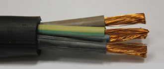
Power flexible cable type KG
The design of another popular cable, characterized by a high degree of flexibility due to the use of a bundle structure of current-carrying conductors.
Design of the KG brand flexible power cable for four working current-carrying conductors. The product has high quality insulation and demonstrates good technical characteristics
The design of this type provides for the presence of up to six current-carrying wires inside the shell. Operating temperature range -60…+50°С. Mainly, the KG variety is used to connect power equipment.
Design data for paper-insulated cables (per 1 km)
Table 3.29
| Core cross-section, mm2 | r0, Ohm | 6kV | 10 kV | 20 kV | 35 kV | |||||
| Aluminum | x0, Ohm | b0, kvar | x0, Ohm | b0, kvar | x0, Ohm | b0, kvar | x0, Ohm | b0, kvar | ||
| 10 | 1,84 | 3,10 | 0,110 | 2,3 | – | – | – | – | – | – |
| 16 | 1,15 | 1,94 | 0,102 | 2,6 | 0,113 | 5,9 | – | – | – | – |
| 25 | 0,74 | 1,24 | 0,091 | 4D | 0,099 | 8,6 | 0,135 | 24,8 | – | – |
| 35 | 0,52 | 0,89 | 0,087 | 4,6 | 0,095 | 10,7 | 0,129 | 27,6 | – | – |
| 50 | 0,37 | 0,62 | 0,083 | 5,2 | 0,090 | 11,7 | 0,119 | 31,8 | – | – |
| 70 | 0,26 | 0,443 | 0,08 | 6,6 | 0,086 | 13,5 | 0,116 | 35,9 | 0,137 | 86 |
| 95 | 0,194 | 0,326 | 0,078 | 8,7 | 0,083 | 15,6 | 0,110 | 40,0 | 0,126 | 95 |
| 120 | 0,153 | 0,258 | 0,076 | 9,5 | 0,081 | 16,9 | 0,107 | 42,8 | 0,120 | 99 |
| 150 | 0,122 | 0,206 | 0,074 | 10,4 | 0,079 | 18,3 | 0,104 | 47,0 | 0,116 | 112 |
| 185 | 0,099 | 0,167 | 0,073 | 11,7 | 0,077 | 20,0 | 0,101 | 51,0 | 0,113 | 115 |
| 240 | 0,77 | 0,129 | 0,071 | 13,0 | 0,075 | 21,5 | 0,098 | 52,8 | 0,111 | 119 |
| 300 | 0,061 | 0,103 | – | – | – | – | 0.095 | 57,6 | 0,097 | 127 |
| 400 | 0,046 | 0,077 | – | – | – | – | 0,092 | 64,0 | – | – |
Weight and dimensions parameters of the VVG power cable
The approximate external dimensions and weights of individual cables with a cross-section of up to 50 mm2 for packaging and transportation purposes are given in the table. The given values may differ for cables of different batches and manufacturers by 10% less or more.
| Cable cross-section | External size value for packaging and transportation purposes, mm | Weight value for packaging and transportation purposes, kg/km |
| Flat cables | (a x b) | |
| 2x1.5 | 5 x 7.5 | 70 |
| 2x2.5 | 5.5 x 8 | 90 |
| 2x4 | 6 x 9.5 | 140 |
| 2x6 | 7 x 10.5 | 180 |
| 3x1.5 | 5 x 9.5 | 95 |
| 3x2.5 | 5.5 x 11 | 135 |
| 3x4 | 6 x 13 | 200 |
| Stranded cables | Diameter | |
| 3x1.5 | 8 | 90 |
| 3x2.5 | 9,5 | 135 |
| 3x4 | 11 | 200 |
| 3x6 | 12 | 260 |
| 3x10 | 14,5 | 410 |
| 3x16 | 17 | 590 |
| 3x25 | 20,5 | 810 |
| 3x35 | 23 | 1300 |
| 3x50 | 27 | 1700 |
| 3x4+1x2.5 | 12 | 230 |
| 3x6+1x4 | 14 | 310 |
| 3x10+1x6 | 16 | 480 |
| 3x16+1x10 | 19 | 650 |
| 4x1.5 | 8,5 | 110 |
| 4x2.5 | 10 | 170 |
| 4x4 | 12 | 240 |
| 4x6 | 13 | 320 |
| 4x10 | 16 | 510 |
| 4x16 | 19 | 750 |
| 4x25 | 23 | 1150 |
| 4x35 | 26 | 1550 |
| 4x50 | 31 | 2200 |
| 5x1.5 | 9,5 | 135 |
| 5x2.5 | 11 | 205 |
| 5x4 | 13 | 300 |
| 5x6 | 14 | 405 |
| 5x10 | 17,5 | 630 |
| 5x16 | 21 | 950 |
| 5x25 | 26 | 1450 |
| 5x35 | 29 | 1900 |
| 5x50 | 35 | 2700 |
Total: how to choose a cable for wiring?
- We decide on the type of cable. NYM would be a better choice, but this wire is quite expensive. If your budget is limited, you can take VVG. For wiring in wooden houses, it is better to use the “ng” type, that is, non-flammable.
- We decide on the number of cores . If you have a single-phase network with grounding, you need three wires: phase, neutral and ground. Without grounding - two. For a three-phase network, cables with four cores (three phases and zero) are used.
- We calculate the cable cross-section. We calculate the maximum load from consumers, multiply by a safety factor of 1.5 and look at our plate.
Design of power and control cables - similarities and differences
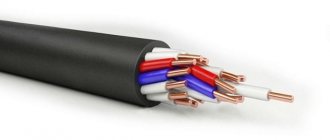
Using the example of two closest “relatives” - VVG and KVVG cables, which each have 3 cores with a cross-section of 2.5 mm2 - let’s look at the visual differences between the control cable and the power cable.
For both cables, the insulation of individual cores and sheath is made of PVC plastic (two letters B in the marking), there is no protection (letter G - bare). But there is also a difference that can be detected visually.
- The VVG cable has a yellow-green conductor intended for grounding, which may have a diameter smaller than the phase and neutral conductors (usually blue). KVVG counting cores are colored red and blue. The diameter of all cores is the same.
- KVVG is more flexible. Its smallest bending radius is 3 outer diameters, while for VVG this parameter is 10.
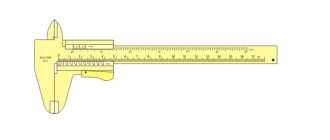
- Cables have different thicknesses. Each core of the control wire has an outer diameter of 0.7 mm, while for the power wire it is 0.8 mm. The thickness of the outer shell is 1.2 mm and 1.5 mm, respectively.
Table 2 shows differences in the characteristics of VVG and KVVG cables that cannot be determined visually.
Table 2. Additional differences between VVG and KVVG
| Characteristic | VVG (power) | KVVG (control) |
| Laying method | Inside and outside buildings. Not recommended underground | Possible underground installation, resistant to aggressive environments. |
| Cable temperature | 80°C | 70° C |
| Life time | 30 years | 15 years - in trenches; 25 years – in rooms, tunnels, canals |
| Resistance to electrical breakdown | 3000 V for 10 min. | 2500 V for 5 min. |
Can I use one cable instead of the other?
If necessary, the KVVG can be replaced with a power VVG. However, you need to keep in mind that the second cable is more expensive, more demanding in terms of operating conditions and less flexible.
The opposite option is possible only in the case of low permissible voltages, as well as currents noticeably lower than the limit for a given cross-section.
A little theory
First of all, let's define what we mean by a power cable.
You can often find an erroneous interpretation of this definition, even among electrical specialists.
Many people understand by power any, for example, a copper power cable for connecting a powerful load, for example, a three-phase electric motor. This is not true.
A power cable is a special kind of electrically conductive system for transmitting industrial frequency electricity from distribution substations, power plants and other types of electric generators to the consumer, which can be a system for providing electric current to final or intermediate consumers.
At first glance it may seem overly confusing and complicated, but in reality everything is not so scary:
An electrically conductive system should be understood as a structure made of conductive cores and, as a rule, multilayer insulation, as well as, in some cases, protection from mechanical stress and damage to the cable.
Industrial frequency is the frequency of alternating current accepted in the national economy. For example, in our country it is 50 Hz, but there are other countries with different standards, for example, in the USA it is 60 Hz.
The electric current supply system is the electrical wiring in the house, power distribution substation, production workshop, etc.
The end consumer is a device that uses electricity and converts it into useful work, for example an electric motor.
Thus, a power cable is a simple transmitter of electricity from the place of its production and distribution to the place where it will be redistributed and used.
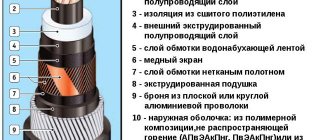
Screens, fillers and shells
The design of a power cable includes the required layers between the insulation:
- screens;
- fillers;
- shells;
- protective coatings.
Screens are designed to protect outer layers from electromagnetic influence. The elements are made of foil and paper treated with a special compound.
Fillers are made in the form of bundles of plastic, rubber, and paper tapes. The elements allow you to adjust the tightness of the junction of parts of the structure. The compositions make the product airtight, resistant to mechanical stress, and give it the required shape.
Sheaths are designed to protect the surfaces of the wire. Parts of the structure are made of alloys of aluminum, lead, non-flammable plastic and rubber. Surfaces can be smooth or corrugated. Sheaths prevent deformation of the wire from the action of water and acid-base compounds.
The final components of the design are protective covers (cushion, armored cover). Armor made of galvanized strips and wires gives the product strength.
Classification of cables for wiring
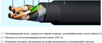
Each cable consists of several copper cores of a certain cross-section. In turn, the cores in the cable can be single-wire monolithic or multi-wire. Each core is enclosed in a protective sheath made of rubber, polyethylene or PVC plastic. Note that any cable used for electrical wiring has at least two layers of insulation: the first envelops the core, and the second collects all the conductive wires into a bundle.
The most popular types of wires for wiring in a house and apartment are:
- VVG
- NYM
- PUNP
Let's look at what these types of cables are and where they are used.