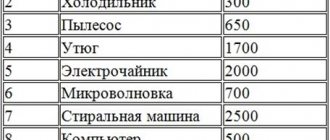
In many areas of energy supply, professional electricians and installers give preference to KG and KG-HL cables (a different climatic version of the first). The main features of these products that set them apart from competitors are increased flexibility and resistance to extreme low or high temperatures.
The KG cable is used everywhere, but in most cases it is used for switching electrical appliances of enormous power (for example, a welding machine).
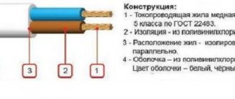
Description and design of the KG cable
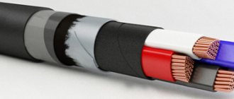
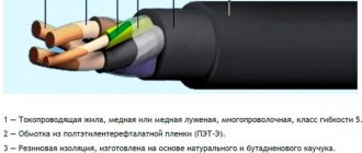
KG is a flexible power cable with copper conductors with insulation and a rubber sheath without protective covers (armor).
Explanation of the designation:
"K" - cable; "G" - flexible.
The most common KG cables are in the usual version with one, two or three main conductors and three main conductors and a grounding conductor (the so-called “three plus”).
To the designation of a KG cable in a tropical version, add the letter “T” through a hyphen (example: KG-T), for a cable in a cold-resistant version – add the letters “HL” through a hyphen (example: KG-HL).
The letter “n” is added to the designation of cables with a neutral conductor (example: KGn), the letter “v” is added to the designation of cables with one or two auxiliary conductors (without grounding and neutral conductors) (example: KGv).
Example of designation: KGn - KHL 2x25+ 1x16 - KG cable with a zero core in the “HL” version with two main cores with a cross-section of 25 mm2.
Since KG cables are intended for intensive operation in a wide temperature range, the technical specifications establish requirements for structural, electrical and mechanical parameters for both new cables and limit standards for cables during operation.
KG cables can have from one to five cores with a cross-section from 0.75 mm2 to 120 mm2.
The range of cross-sections of the main cores depending on the total number of cores is shown in the table.
| Number of cores | Nominal cross-section, mm 2 | ||
| Main | Neutral or ground | Auxiliary | |
| 1 | — | — | 2,5-120 |
| 2 and 3 | — | — | 0,75 – 120 |
| 2 and 3 | 1 | — | |
| 2 and 3 | — | — | 2,5 – 70 |
| 2 and 3 | — | 2 | 2,5 – 70 |
| 4 | — | — | 1,0 — 95 |
| 5 | — | — | 1,0 – 25 |
The cross-sections of neutral conductors, grounding and auxiliary conductors, depending on the cross-section of the main conductors up to 50 mm2, are given below. At the request of the consumer, other sections of the grounding conductor are allowed.
| Main veins | 0,75 | 1,0 | 1,5 | 2,5 | 4 | 6 | 10 | 16 | 25 | 35 | 50 |
| Zero core | 0,75 | 1,0 | 1,5 | 2,5 | 2,5 | 4 | 6 | 10 | 16 | 16 | 25 |
| Grounding conductor | 0,75 | 1,0 | 1,0 | 1,5 | 2,5 | 4 | 6 | 6 | 10 | 10 | 16 |
| Auxiliary core | — | — | 1,5 | 1,5 | 2,5 | 4 | 6 | 6 | 10 | 10 | 10 |
Current-carrying conductors must be twisted from individual copper wires (for tropical cables made of tinned) with a single wire diameter not exceeding that indicated in the table.
| Nominal conductor cross-section | 0,75 | 1,0 | 1,5 | 2,5 | 4 | 6 | 10 | 16 | 25 | 35 | 50 |
| Maximum single wire diameter | 0,21 | 0,21 | 0,26 | 0,26 | 0,31 | 0,31 | 0,41 | 0,41 | 0,416 | 0,41 | 0,41 |
The rubber insulation must be separated from the core without sticking, for which purpose a synthetic film can be laid between the core and the insulation.
The nominal and minimum values of the radial insulation thickness for cables with a cross-section of up to 50 mm2 are given in the table.
| Nominal cross-section, mm 2 | Nominal insulation thickness, mm | Minimum insulation thickness, mm |
| 0,75 – 1,5 | 0,8 | 0,62 |
| 2,5 | 0,9 | 0,71 |
| 4 and 6 | 1,0 | 0,8 |
| 10 and 16 | 1,2 | 0,98 |
| 25 and 35 | 1,4 | 1,16 |
| 50 | 1,6 | 1,34 |
The insulated conductors must have a distinctive color (the preferred one is shown in the table), while the insulation of the neutral conductors should be blue, and the insulation of the grounding conductors should be yellow-green (designation with the number “0” is allowed). The coloring must be continuous along the length; coloring in the form of a longitudinal stripe with a width of at least 2 mm is allowed.
| Number of cores | Preferred color scheme for core insulation | |
| With grounding conductor | With a neutral conductor and without a grounding conductor and a neutral conductor | |
| 3 | Yellow-green, blue, brown | Blue, black, brown |
| 4 | Yellow-green, blue, black brown | Blue, black, brown, black or brown |
| 5 | Yellow-green, blue, black brown, black or brown | Blue, black, brown, black or brown, black or brown |
Insulated conductors must be twisted, and twisting with an alternating change in direction is allowed for cables with a cross-section of the main conductors of 10 - 95 mm2.
It is allowed to twist cores with intercore filling in the form of bundles of rubber or synthetic threads.
The sheath must be applied in such a way that it can be easily separated from the core insulation. To do this, a synthetic film can be laid between the core insulation and the sheath. The shell color is predominantly black. In single-core cables, it is allowed to replace the insulation and sheath with an insulating protective sheath, applied in one layer with a thickness of at least twice the thickness of the insulation. The nominal and minimum values of the sheath thickness of the most common cable sections up to 50 mm2 are given in the table.
| Cable cross-section, mm2 | Nominal shell thickness, mm | Minimum shell thickness, mm |
| 1x10 | 1,8 | 1,43 |
| 1x16 | 1,9 | 1,52 |
| 1x25 | 2,0 | 1,6 |
| 1x35 | 2,2 | 1,77 |
| 2x1.5 | 1,5 | 1,18 |
| 2x2.5 | 1,7 | 1,35 |
| 2x4 | 1,8 | 1,43 |
| 3x1.5 | 1,6 | 1,26 |
| 3x2.5 | 1,8 | 1,43 |
| 3x4 | 1,9 | 1,52 |
| 3x1.5+1x1.5 (4x1.5) | 1,7 | 1,35 |
| 3x2.5+1x1.5 | 1,9 | 1,52 |
| 3x4+1x2.5 | 2,0 | 1,6 |
| 3x6+1x4 | 2,1 | 1,69 |
| 3x10+1x6 | 3,3 | 2,71 |
| 3x16+1x6 | 3,5 | 2,88 |
| 3x25+1x10 | 3,8 | 3,13 |
| 3x35+1x10 | 4,4 | 3,64 |
| 3x50+1x16 | 4,8 | 3,98 |
The difference between the maximum and minimum values of the outer diameter of the cable measured in one section (ovality) should not exceed 15% of the outer diameter.
Explanation of markings
Let's decipher the possible letter designations for the KG cable and its modifications:
- “K” – cable;
- “G” – flexible type;
- “N” – there is an additional protective layer that prevents combustion;
- “T” – can be successfully used in tropical climates with a minimum permissible air temperature of -10 degrees. Celsius;
- “HL” – intended for use in cold climates with a minimum permissible temperature of -60 degrees. Celsius.
Modifications
The KG cable is available in various modifications. Two of them, KGVV and RKGM, will be discussed below. The KGVV wire is characterized by the presence of polymer insulation (instead of rubber as in the standard one). It could be polyvinyl chloride. Thanks to this, the service life of the product increases significantly (25 years). Using KGVV, they switch bulky and high-power equipment, devices connected to AC and DC sources. Examples include excavators working in a quarry, cranes, etc.
The polyvinyl chloride insulating layer significantly expands the operating temperature range, which ranges from -50 to +50 degrees. Celsius. Thanks to this, the KGVV cable does not have climatic modifications, since it can be used under any conditions.
When connecting the KGVV to an AC electrical network, you need to monitor the maximum voltage and frequency - up to 660/1000 V and 60 Hz, respectively. When switching with DC networks, the voltage should be in the range of 1000-1500 V. The non-flammable properties of KGVV are manifested exclusively when installed alone. Group installation of a cable with other wires does not provide such protection.
Another modification of the CG is RKGM. This abbreviation stands for as follows:
- “R” – rubber insulation;
- “K” – layer of organosilicon;
- “G” – bare;
- “M” – copper conductors.
When examining the design of the RKGM, one can find strands of copper wires, an insulating layer of silicone rubber and a high-quality braid of glass fiber impregnated with varnish.
For other technical and operational parameters, we highlight the following:
- The cross-sectional area of the cores is in the range of 0.75-120 square meters. mm;
- bending radius – from two outer diameters;
- operating temperature range – from -60 to +180 degrees. Celsius;
- withstands operation in conditions of 100% humidity at a temperature of +35 degrees. Celsius;
- It is possible to connect to an alternating current source at a voltage of 660 V and a frequency of 40 Hz.
Often, electrical products are used to connect equipment and electrical appliances to AC and DC networks. It is possible to install the cable by air, which is due to increased resistance to precipitation, mechanical and wind loads, and ultraviolet rays of the sun.
The main requirement is related to the absence of contact area with a chemically aggressive environment, mineral or natural oils. Thus, before connecting the RKGM, make sure in advance that there are no oil stains indicating equipment leakage. If there are any, then you must first eliminate any leaks by cleaning the surface. Similar to other types of cables, RKGM is selected depending on the load.
Difference between cables KG, KG-HL and KGN
Regardless of the type of cable, it is suitable for all areas of operation listed in the first section of the article. Any CG is resistant to ultraviolet radiation, and is also used for switching mobile units.
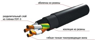
Structurally, the cores of each wire consist of copper wires, have insulation and a separating layer of polyethylene terephthalate. Manufacturers choose natural or vulcanized rubber to insulate the cores, while the sheath is made of isoprene synthetic rubber.
There are several types of cable depending on the climatic version. Let's look at the main differences:
- KG is a standard wire with an operating temperature range from -40 to +50 degrees. Celsius;
- KG-HL – modification for cold climates (from -60 to +50 degrees Celsius);
- KG-T – for tropical climates (from -10 to +55 degrees Celsius);
- KGN is a product characterized by resistance to oils, having a fireproof shell (from -30 to +50 degrees Celsius) and intended for use in aggressive environments.
KG-T stands out from the rest in that the current-carrying copper conductors are additionally coated with tin or its alloy with lead (40/60 ratio). The insulation of such a wire, which can be used in tropical areas with a hot and humid climate, must meet special requirements. Fungicides are added to butadiene rubber to prevent the formation and spread of mold or mildew. These substances are not used in other modifications of CG.
The KG-HL cable is used in low temperature conditions (for example, in the Arctic and Antarctic). To create such a product, new technologies for protecting insulation and rubber were required. The latter must withstand extremely low temperatures. To do this, organosilicon substances are added to the composition of butadiene or natural rubber. Thanks to this approach, the minimum permissible temperature was increased to -60 degrees. Celsius.
KGN contains chloroprene rubber, which makes it possible to increase resistance to oil and make the rubber less flammable. Such products are successfully used in mines and quarries.
A regular KG can be easily replaced with other modifications - KG-HL and KGN. On the other hand, reverse replacement can lead to dire consequences. The situation is similar with wires intended for use in networks with voltages of 380 and 660 V. Direct replacement is acceptable, reverse replacement is not.
Conditions for installation and operation of the KG cable
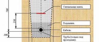
The cable in the standard version is intended for operation at ambient temperatures from minus 40°С to plus 50°С, in the tropical version – from minus 10°С to plus 55°С, in the cold-resistant version – from minus 60°С to plus 50° WITH. Can be laid without preheating at a temperature not lower than minus 40°C. The bending radius during installation and operation must be at least 8 outer diameters of the cable, tensile forces must not be more than 2 kgf per 1 mm2 of the total copper cross-section of all cores. Service life is 4 years from the date of manufacture of the cable.
Product advantages:
- Wide range of sections, different types of insulation.
- Possibility of mobile installation and power supply of non-stationary equipment due to the high flexibility of the wire.
- Resistance to aggressive environments, including engine oil, gasoline, diesel fuel.
- Possibility of application in various industrial sectors, in particular, where special requirements for fire safety are imposed.
- Suitable for use at low temperatures and installation in refrigeration units.
Are you looking for flexible cables in Moscow and considering only high-quality products? Then come to us! Thanks to high-tech production, our products have high performance characteristics and are safe to use. Contact us!
Technical characteristics of the KG cable
The electrical resistance of copper conductors at direct current for cables with a cross-section of up to 50 mm2 when supplied from the manufacturer must be no more than that indicated in the table.
| Nominal conductor cross-section | 0,75 | 1,0 | 1,5 | 2,5 | 4 | 6 | 10 | 16 | 25 | 35 | 50 |
| Core resistance, Ohm/km | 26,0 | 19,5 | 13,3 | 7,98 | 4,95 | 3,3 | 1,91 | 1,21 | 0,78 | 0,554 | 0,386 |
During storage and operation, the electrical resistance of the current-carrying cores of the KG cable should not increase by more than 10% of that indicated in the table.
The electrical resistance of cable insulation when delivered from the manufacturer, recalculated per 1 km of length at a temperature of 20°C, must be at least 50 MOhm, and during the entire period of storage and operation it must not decrease less than 1 MOhm. Finished cables must withstand testing with an alternating voltage of 2.5 kV at a frequency of 50 Hz for 5 minutes.
Cables must withstand multiple bends (with a cross-section of main cores up to 4 mm2 - at least 30,000 bends, with a cross-section of 6-16 mm2 - at least 9,000, with a cross-section of 25-50 mm2 - at least 6,000).
Other GOSTs
GOST R IEC 60245-4-2002 Cables with rubber insulation for rated voltages up to 450/750 V inclusive. Cords and flexible cables GOST R IEC 245-4-97 Cables with rubber insulation for rated voltage up to 450/750 V inclusive. Cords and flexible cables GOST 11092-82 Input-connection communication cables. Technical specifications GOST 15125-92 Symmetrical high-frequency communication cables with cord-polystyrene insulation. Technical specifications GOST 26636-85 Symmetrical high-frequency communication cables. General technical conditions GOST R 54429-2011 Symmetrical communication cables for digital transmission systems. General technical conditions GOST 27893-88 Communication cables. Test methods GOST R 55025-2012 Power cables with plastic insulation for rated voltage from 6 to 35 kV inclusive. General technical conditions GOST R 53769-2010 Power cables with plastic insulation for rated voltage 0.66; 1 and 3 kV. General technical conditions GOST 31996-2012 Power cables with plastic insulation for rated voltage 0.66; 1st and 3rd quarter General technical conditions GOST 18409-73 Power cables with paper insulation impregnated with a non-drip compound. Technical specifications GOST 11160-76 Power cables with aluminum conductors with plastic insulation in a polyvinyl chloride sheath for agriculture GOST R 58342-2019 Power and control cables for use in electrical installations in explosive environments. General technical conditions GOST 24183-80 Power cables for stationary installation. General technical conditions
Requirements for packaging of KG cable
Cables can be supplied on drums or in coils. The diameter of the drum neck or the internal diameter of the coil must be no less than 12 external diameters of the cable.
Standard cable lengths must be at least 150 m for sections up to 35 mm2 inclusive and at least 125 m for sections from 50 mm2 and above. In one delivery batch, a certain percentage (no more than 20) of cables with a length of at least 20 m is allowed. No more than 5 pieces of cable can be wound on a drum. Cable lengths when supplied in coils are agreed upon between the manufacturer and the consumer.
Requirements for marking cable KG
Cables must be marked in the form of an inscription printed on the surface of the sheath or in the form of a tape under the cable sheath along the entire length or in the form of a distinctive thread. The inscription made on the surface of the sheath or tape must contain the trademark or name of the manufacturer and the year of manufacture of the cable. Cables in cold-resistant design must be additionally marked with the letters “ХЛ”. Marking in the form of an inscription can be made in relief or printed. The distance between inscriptions should not exceed 550 mm on the shell and 275 mm on the tape.
The drum cheek or label attached to the coil or drum must indicate:
— trademark or name of the manufacturer; — symbol of the cable (full indicating the number of cores and cross-section); — length of each cable section in meters; — gross weight in kilograms (determined approximately by calculation, based on the actual length and estimated weight); — date of manufacture (year, month); — drum or coil number. The label must bear a technical control stamp and a certification mark.
Weight and size parameters of cable KG
The approximate external dimensions and weights of individual cables with a cross-section of up to 50 mm2 for packaging and transportation purposes are given in the table. The given values may differ for cables of different batches and manufacturers by 10% less or more.
| Cable cross-section | External size value for packaging and transportation purposes, mm | Weight value for packaging and transportation purposes, kg/km |
| 1x10 | 11,1 | 230 |
| 1x16 | 12,4 | 310 |
| 1x25 | 14,6 | 450 |
| 1x35 | 16,4 | 590 |
| 2x1.5 | 9,4 | 130 |
| 2x2.5 | 11,2 | 190 |
| 2x4 | 13,5 | 280 |
| 3x1.5 | 10,1 | 160 |
| 3x2.5 | 12,0 | 230 |
| 3x4 | 14,5 | 350 |
| 3x1.5+1x1.5 (4x1.5) | 11,1 | 200 |
| 3x2.5+1x1.5 | 13,2 | 280 |
| 3x4+1x2.5 | 15,5 | 400 |
| 3x6+1x4 | 18,0 | 560 |
| 3x10+1x6 | 23,4 | 950 |
| 3x16+1x6 | 27,6 | 1300 |
| 3x25+1x10 | 33,1 | 1950 |
| 3x35+1x10 | 36,5 | 2400 |
| 3x50+1x16 | 42,4 | 3400 |
KG cable load currents
The maximum permissible load currents at an ambient temperature of 25°C for cables with a cross-section of up to 50 mm2 are indicated in the table.
| Nominal cross-section, mm2 | Permissible load current, A | ||
| With one main residential | With two main cores | With three main cores | |
| 0,75 | — | 24 | 22 |
| 1,0 | — | 28 | 24 |
| 1,5 | — | 35 | 31 |
| 2,5 | 59 | 47 | 42 |
| 4 | 89 | 60 | 55 |
| 6 | 115 | 75 | 69 |
| 10 | 144 | 97 | 88 |
| 16 | 189 | 128 | 116 |
| 25 | 240 | 162 | 150 |
| 35 | 298 | 200 | 180 |
| 50 | 362 | 245 | 226 |
Available methods for quality control of KG cable
Control methods are presented that, although not strictly corresponding to the specifications, allow making preliminary conclusions about the quality of the cable if the measured values differ significantly from the regulated ones. The final conclusion about the compliance of the cable with the specifications can be made only after testing the cable in a specialized laboratory using strict methods and in the volumes specified in the technical specifications.
Visual inspection The following can be checked: the number and color of cores, the integrity of the insulation and sheathing and the ability to separate them without damage.
Measurement of structural dimensions Can be checked using suitable measuring instruments: thickness of insulation and sheath, diameter of wires in the core dpr. Calculating the cross-section of the core using the formula 0.785dpr2N (where N is the number of wires in the core) is not a strict method for controlling the cross-section of the cores, because confirmation of cross-section compliance is electrical resistance, however, a significant deviation of the calculated cross-section from the nominal (more than 15%) may serve as a basis for doubts about the quality.
Measurement of the electrical resistance of current-carrying conductors Can be carried out on a finished cable with an ohmmeter with a suitable measurement limit (for cables with a small cross-section at a normal length in a coil or on a drum, it can be several Ohms) and recalculated for a length of 1 km. If the cable has twisted cores, the obtained values should be reduced by 1.02 times. Particular attention should be paid to making good contact with the test leads.
Application of flexible cables
Flexible cables are designed for mobile or fixed installation of power, lighting or distribution networks. They are used to connect mobile equipment and mechanisms operating at voltages up to 1 kV. At the same time, this brand is distinguished by high performance characteristics under conditions of complex bending loads. Different types of products allow you to perform a whole range of tasks.
Thus, a flexible control cable is used when installing measuring units, control circuits, and alarm systems. The welding cable is designed to power the electrode holders of welding installations. Using a multi-core flexible cable, any inter-device connections are made, electric locks and other electronic devices are installed on doors.