To measure large currents, as a rule, a non-contact method is used - special current clamps. Current clamp is a measuring device that has a sliding ring that covers an electrical wire and the amount of current flowing is displayed on the device indicator.
The superiority of this method is undeniable - in order to measure the current strength there is no need to break the wire, which is especially important when measuring large currents. This article describes a DC current clamp , which is quite possible to make with your own hands.
Homemade current (current) clamps on a Hall sensor, attachment to a multimeter
Schematic diagram and design of homemade current clamps for measuring current, attachment to a multimeter.
To measure large currents, they usually use a non-contact method - special “current clamps”. Let me remind you that this is an electronic measuring device, like a multimeter, which has a kind of clothespin sticking out from the top.
This clothespin is attached to a wire and the current readings in this wire appear on the digital display. The advantages of this method are obvious - in order to measure the current strength, you do not need to break the circuit, which is especially important when measuring large currents.
What to remember
It is important to remember that all work on the construction and maintenance of electrical networks, as well as carrying out electrical measurements, must be performed only by specially trained personnel who have all the necessary permits and work orders for performing work under voltage. Follow the electrical safety rules, namely: use shoes with rubber soles (insulating galoshes), use insulating rubber gloves, work with a partner.
In addition, avoid touching live parts with bare parts of your body and prevent the formation of an electric arc. If you are not a certified specialist and work without a partner and a work order, you completely assume all responsibility for possible damage and injuries that you may receive in the process of performing them. Electricity is dangerous to life, it is important to remember this and follow all safety measures. Especially when it comes to carrying out work in switchboards. After all, the current strength in them is higher than in the home network, as well as the voltage. This is where current clamps are mainly used. Do not neglect the opportunity to seek help from trained specialists, do not risk your life in vain. If you still decide to carry out such work yourself, study the video, carefully read the instructions on how to use current clamps, and only after that, in compliance with all safety measures, proceed to work. How to use a clamp meter video, see below:
Design
You can make a “current clamp” for a regular multimeter yourself if you have a sensitive Hall sensor, for example, UGN3503. Figure 1 shows the design of a homemade “pincer”.
You need, as already mentioned, a hall sensor, as well as a ferrite ring with a diameter of 20-25 mm and a large “crocodile”, for example, to connect something to a car battery.
The ring must be accurately and accurately broken into two halves. To do this, the ring must first be filed with a medical file for ampoules. Then, treat the broken surfaces with fine sandpaper. On one side, stick a thick paper gasket (drawing paper) onto one of the halves of the ring. On the other side, stick a Hall sensor onto one of the halves of the ring.
It is most convenient to glue with epoxy glue, but so that the sensor fits tightly to the place where the ring breaks. Then, folding both halves of the ring as shown in Figure 1, they need to be inserted into the “crocodile’s mouth” and glued to the “crocodile’s jaws” with the same epoxy glue.
The result should be a structure schematically shown in Figure 1. When pressing on the “crocodile” handles, the ferrite ring should open along with its “jaws”.
Rice. 1. Design of homemade current measuring (current) clamps.
Proven "budget" option
Here's what you need to do to make this option:
- cut a groove in the ferrite ring along the thickness of the housing;
- Place MS on epoxy glue;
- make a certain number of turns on the ring (the number of turns will depend on the specific voltage);
- the result will be a contactless version of the relay operating on an electromagnetic basis.
The accuracy of operation of such a DT and the regularity are quite high. The only drawback of the circuit is the number of turns, determined purely empirically. In fact, there are no calculations of a specific type anywhere. It is necessary to determine the number of turns for a specific core.
Schematic diagram
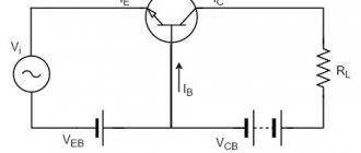
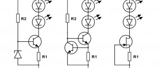
Now from the electronic part. The schematic diagram of the multimeter attachment is shown in Figure 2. When current passes through a wire, a magnetic field appears around it, the lines of force of which penetrate the Hall sensor, and some constant voltage appears at its output.
This voltage is amplified in power by operational amplifier A1 and supplied to the input of the multimeter. Dependence of output voltage on current: 1A = 1 mV. Trimmer resistors R3 and R6 must be multi-turn.
Rice. 2. Schematic diagram of homemade current measuring (current) clamps.
711 chip circuit
ATTENTION! A completely simple way to reduce fuel consumption has been found! Don't believe me? An auto mechanic with 15 years of experience also didn’t believe it until he tried it. And now he saves 35,000 rubles a year on gasoline! Read more"
ACS 711 is the same chip that will make it possible to produce a current sensor or TD based on a Hall sensor (Hall sensor). The BH of such a sensor will be almost 100 kHz, which will be quite effective for measurements.
This type of chip has an output that is integrated with the amplifier. The latter, in turn, due to its efficiency, is capable of increasing the circuit’s capabilities up to 1 A/V.
As for power supply, voltage is supplied to the amplifier through the use of an internal 2-polar type source. This could be the NSD10 variant or some other. The microcircuit itself is powered by a stabilizer having an output voltage of 3.3 V.
Setting up
To set up, you need a laboratory power supply with an output current of at least 3A, with a built-in ammeter.
First, connect the attachment to the multimeter and calibrate it to zero by adjusting R3 with R2 in the middle position. Then, before each measurement, you will need to set zero with the variable resistor R2.
Set the source to the minimum voltage and connect a powerful load to it, for example, a lamp from a car headlight.
Attach a “clamp” to one of the wires going to this lamp (as shown in Figure 1). Increase the voltage until the source ammeter shows 2-2.5K.
Adjust R6 so that the multimeter reading in millivolts is equal to the source ammeter reading in amperes. Check the readings by changing the current in one direction or the other (decreasing - increasing the current and comparing with the source ammeter).
Using this attachment you can measure current up to 500A. For example, you can measure the current consumption of a car starter at the moment the engine starts.
Source
DC current clamp - do-it-yourself multimeter attachment. Description
To measure large currents, as a rule, a non-contact method is used - special current clamps. Current clamp is a measuring device that has a sliding ring that covers an electrical wire and the amount of current flowing is displayed on the device indicator.
The superiority of this method is undeniable - in order to measure the current strength there is no need to break the wire, which is especially important when measuring large currents. This article describes a DC current clamp , which is quite possible to make with your own hands.
Working principle of clamp meters
The principle of operation of electrical clamp meters is in many ways similar to the operation of a substation - there is an instrument transformer and a device for measuring electrical parameters: current, voltage, etc. As you know, any transformer, including a measuring one, consists of two or more windings.
In electrical measuring clamps, the first winding is a conductor, the current strength of which we measure. The second winding with a large number of turns is located in the tongs themselves. The device analyzes the current in the secondary winding and, taking into account the known transformation ratio, calculates the amount of electric current in the conductor.
In the figure below you can clearly see the operating principle of this measuring device.
It is worth noting that measuring current with electrical measuring tongs is not a difficult and very convenient task. You just need to set the required value on the handle, open the handles, pass the conductor through the pliers and release one handle.
Description of the design of homemade current clamps
To assemble the device you will need a sensitive Hall sensor, for example, UGN3503. Figure 1 shows the device of a homemade pliers. You need, as already mentioned, a Hall sensor, as well as a ferrite ring with a diameter of 20 to 25 mm and a large “crocodile”, for example, similar to the one on the wires for starting (lighting) a car.
The ferrite ring must be accurately and accurately sawed or broken into two halves. To do this, the ferrite ring must first be filed with a diamond file or an ampoule file. Next, sand the fracture surfaces with fine sandpaper.
On one side, glue a gasket from drawing paper to the first half of the ferrite ring. On the other side, stick a Hall sensor on the other half of the ring. It is best to glue it with epoxy glue, you just need to make sure that the Hall sensor is in good contact with the fracture zone of the ring.
The next step is to connect both halves of the ring and wrap it around it with a crocodile and glue it. Now, when you press the crocodile handles, the ferrite ring will diverge.
Electronic circuit of current clamps
The schematic electrical diagram of the multimeter attachment is shown in Figure 2. When current flows through an electrical wire, a magnetic field appears around it, and the Hall sensor detects the power lines passing through it and generates some constant voltage at the output.
This voltage is amplified (by power) by op amp A1 and goes to the multimeter terminals. The ratio of the output voltage to the flowing current: 1 Ampere = 1 mVolt. Trimmer resistances R3 and R6 are multi-turn. To set up, you need a laboratory power supply with a minimum output current of about 3A, and a built-in ammeter.
First, connect this attachment to the multimeter and set it to zero by changing the resistance R3 and the middle position of R2. Next, before any measurement it will be necessary to set zero with potentiometer R2. Set the power supply to the lowest voltage and connect a large load to it, for example, an electric lamp used in car headlights. Then hook the “pliers” onto one of the wires connected to this lamp (Figure 1).
Increase the voltage until the power supply ammeter shows 2 amperes. Tighten resistance R6 so that the voltage value of the multimeter (in millivolts) matches the data on the power supply ammeter in amperes. Check the readings a few more times, changing the current strength. Using this attachment it is possible to measure current up to 500A.
Source
Ready diesel engine MLX91206
A cumulative circuit that uses the thinnest layer of a ferromagnetic structure or IC. The latter acts as a magnetic field switch, thereby providing high gain and adjusting the noise signal equivalence. This version of the DT is more relevant for measuring AC voltage up to 90 kHz with ohmic insulation, which is characterized by insignificant introduced losses and short response time.
In addition, the advantages include ease of assembly and small fuselage dimensions.
DT MLX91206 is a regulator that so far meets the demand in the automotive industry. In addition, DTs of this type are used in other power sources: for overload protection, in motor systems, etc.
Most often, diesel engines on the MLX91206 chip are used in hybrid automotive systems, as auto-inverters.
It is also interesting that this sensor is equipped with a high-quality overvoltage protection system, which allows it to be used as a separate regulator integrated into the cable.
The operating principle of a sensor of this type is based on the transformation of the magnetic field arising from currents passing through the conductor. The circuit does not have an upper limit on the measured voltage level, since the output and its parameters in this case depend on the conductor size and the immediate distance from the DT.
As for the differences between this type of diesel engine and similar ones:
- Analog output speed, which is higher (helped by the 12-bit DAC).
- Availability of programmable switch.
- Reliable protection against overvoltage and overvoltage.
- PWM output with 12-bit ADC resolution.
- Huge bandwidth, the parameters of which are equal to 90 kHz and much more.
In a word, this type of DT is a compact and efficient sensor manufactured using Triasis Hall technology. This type of technology is considered classical and traditional; it is sensitive to the flux density, which is applied exactly parallel to the surface.
The measurements that can be carried out using a ready-made sensor made using Triasis Hall technology are divided into measurements of low voltage up to 2 A, current average. values up to 30 A and currents up to 600 A (large).
Let's take a closer look at the capabilities of these measurements.
- Small currents are measured using a sensor by increasing the magnetic field parameters through a coil around the diesel generator. In this case, the sensitivity of the measurement will be determined by the dimensions of the coil and the number of turns.
- Currents in the range of up to 30 A or average currents are measured taking into account the voltage tolerance and overall power dissipation of the trace. The latter must be quite thick and wide, otherwise continuous processing of the average current will not be achieved.
- Finally, measuring large currents involves using copper and thick traces that can drive voltage on the back of the PCB.
DC current clamp - do-it-yourself multimeter attachment. Description
To measure large currents, as a rule, a non-contact method is used - special current clamps. Current clamp is a measuring device that has a sliding ring that covers an electrical wire and the amount of current flowing is displayed on the device indicator.
The superiority of this method is undeniable - in order to measure the current strength there is no need to break the wire, which is especially important when measuring large currents. This article describes a DC current clamp , which is quite possible to make with your own hands.
Description of the design of homemade current clamps
To assemble the device you will need a sensitive Hall sensor, for example, UGN3503. Figure 1 shows the device of a homemade pliers. You need, as already mentioned, a Hall sensor, as well as a ferrite ring with a diameter of 20 to 25 mm and a large “crocodile”, for example, similar to the one on the wires for starting (lighting) a car.
Safety precautions when working with current clamps
When working with current clamps
, as when working with any other tool, certain safety precautions should be followed. Therefore, when working with this device it is prohibited:
- exceed the overload capacity of the device specified for a certain measurement range;
- changing the position of the measurement range switch when the current-carrying conductor is in the arms of the magnetic circuit clamps;
- carry out resistance measurements in a live circuit;
- touch, touch unused connectors of current clamps while they are connected to live elements.
ElektroMaster.org DIY repair and maintenance of household electrical appliancesTips, guides..
Yandex.Direct
Ammeter is a device for measuring current in amperes. The scale of ammeters is calibrated in microamperes, milliamperes, amperes or kiloamperes in accordance with the measurement limits of the device.
In an electrical circuit, the ammeter is connected in series with the section of the electrical circuit in which the current is measured; to increase the measurement limit - with a shunt or through a transformer.
(An example of an ammeter with a transformer is a "current clamp"
Current clamp - Ammeter for non-contact measurement of large currents, allows you to measure current strength in a non-contact way with high accuracy, without interrupting the power supply to consumers.
When measuring current, the clamp probes, in which ferrite cores are mounted, seem to wrap around the conductor, remaining completely isolated from open sections of the wires.
Due to the formation of an oscillatory circuit by ferrites when current flows through the conductor, magnetic induction occurs, the value of which is directly proportional to the current flowing through the conductor.
This value is recorded by the current sensors of the current clamps and is converted into a current value, which is either displayed on the display of the current clamps (if it is designed) or outputs the value to an external multimeter through remote probes. Depending on the modification, current clamps can measure the strength of both direct current and alternating current.
general characteristics
The most common ammeters are those in which the moving part of the device with the pointer rotates through an angle proportional to the magnitude of the current being measured.
Ammeters are magnetoelectric, electromagnetic, electrodynamic, thermal, induction, detector, thermoelectric and photoelectric.
Magnetoelectric ammeters measure direct current; induction and detector - alternating current; ammeters of other systems measure the strength of any current. The most accurate and sensitive are magnetoelectric and electrodynamic ammeters. Operating principle
The principle of operation of a magnetoelectric device is based on the creation of torque due to the interaction between the field of a permanent magnet and the current that passes through the winding of the frame. An arrow is connected to the frame, which moves along the scale. The angle of rotation of the arrow is proportional to the current strength.
Electrodynamic ammeters consist of fixed and moving coils connected in parallel or in series. The interaction between the currents that pass through the coils causes deflections of the moving coil and the arrow connected to it. In an electrical circuit, the ammeter is connected in series with the load, and at high voltages or high currents - through a transformer.
The material partially uses information from wikipedia.org
What is measured with a clamp meter?
Two types of sensing elements can be used in the current-sensing parts of the device. Depending on this, current clamps can measure:
- direct and alternating current;
- AC only.
In this case, measurements can be made of the current flowing either through a single conductor or through several conductors.
Using this you can take measurements:
- power of electrical appliances;
- accuracy of readings from electricity metering devices (for example, electricity meters), comparing the readings of current clamps with the readings of the meter;
- actual network load.
How current clamps work and work and how to use them correctly
To diagnose faults in electrical equipment or electrical installations, it is often necessary to measure currents. There are two options: use an ammeter or using a current clamp.
The first option can be done using a regular multimeter, but it is bad because you need to break the circuit, and this is not always possible and not always convenient for making correct measurements.
The second method, clamp meters, allows you to find out the current in the circuit without disconnecting it. In this article we will look at how to use current clamps and how they work.
The operating principle of current clamps is based on the phenomenon of electromagnetic induction. The conductor in which the current is measured is inserted into the magnet and the wire on which the secondary winding is wound.
The measured current in this case is called primary, and the current in the measuring coil (secondary winding) is called secondary. Moreover, its value is proportional to the primary current and can be calculated.
The magnetic circuit of the clamps consists of two parts, one of which is movable; this design is needed in order to open the magnetic circuit using a lever and insert a conductor for measurements.
Current transformers work similarly, but their magnetic core is solid and is placed on a busbar or cable core.
Previously, clamp meters, for the most part, could only measure alternating current, since EMF on a winding can only occur under the condition of an alternating magnetic flux created by an alternating electric current.
Most modern, even the cheapest models, are capable of measuring both direct and alternating currents. DC current measurement is made possible by using a Hall sensor.
It also supports functions standard for multimeters - measuring resistance, voltage, frequency, continuity of circuits, and sometimes it is possible to connect a thermocouple to determine temperatures.
So, a current clamp consists of:
1. Composite moving magnetic circuit.
2. The main part of the housing with a display, a selector for selecting limits or selecting a measured value (if the limits are selected automatically), as well as connectors for connecting probes, for working in Ohmmeter, continuity or voltmeter mode.
3. Inside the case there is a board with microcircuits, sometimes with variable resistors for fine-tuning the measurement accuracy.
To measure current in hard-to-reach places, some clamps are equipped with an additional meter with a flexible sensing element. An example is a product from Fluke; it can be included in a kit or sold separately.
Features and design errors of a current transformer
I would like to draw your attention to the fact that the voltage at the output of the current transformer will be bipolar even if a pulsating unipolar current flows in the measured circuit. A transformer cannot transmit DC voltage. It will transfer only the alternating component of the measured current to the output winding.
One more note. The secondary winding shunt must pass electric current in both directions. It is unacceptable to place a diode in series with the output winding. This can lead to voltage surges on this winding, saturation of the transformer, interference in the measured circuit, and diode breakdown. You can first install a shunt resistor, and only then remove the voltage from it through a diode, or install a bridge with a shunt resistor included in its diagonal. The bridge, as is known, has bidirectional conductivity on the side of the AC inputs.
Current clamps. Current clamp measurement
Current clamps are a convenient tool for measuring current at home and in enterprises. The functionality of such devices is ensured by applying the principle. Let's look at the structure of these devices, the features of their operation and methods of application.
Purpose
Current clamps make it possible to measure the performance of direct current or without de-energizing the conductors. As a result, it becomes possible to control the current consumption and carry out the necessary installation work while the equipment is operating. This feature makes current clamps second in demand in the arsenal of electricians, immediately after the multimeter.
Design
Standard DC current clamps have the following structure:
- Magnetic terminals.
- Holder release button.
- Switch for current measurement method.
- Display.
- Probe connection elements.
- System for recording indicators in the device memory.
Features of operation
Using the device is quite simple. To begin with, the switches are set to the required position. The pliers grasp the contacts, after which the indicators are recorded.
The main difficulty in operating the device is the need to separate a separate electrical conductor. Gripping the wire with the clamps along with the zero and phase leads to a total current that flows through all the wires.
By using current clamps to hold the entire cable, ideally the electrician gets a zero reading. If, with this connection method, the device shows different values, this may indicate a leak in the circuit.
In any case, for proper operation of the measuring unit and obtaining adequate indicators, it is necessary to find a place where it is possible to separate the individual electrical conductors. Sometimes all you need to do is look into the switchboard.
Unfortunately, it is not possible to take measurements with current clamps everywhere, which is an obvious disadvantage of the device. However, this drawback is completely covered by the ability to perform measurements without breaking the circuit.
How to use current clamps: instructions
The measuring device is connected to the electrical conductor in the following sequence:
- A place is selected where it is possible for the pliers to freely grasp a single cable.
- The mode switch knob is moved to the required position. For AC networks the designation “A” is used
" With constant current, the “A-” indicator is selected. The corresponding data, indicating the choice of one mode or another, is duplicated on the display.
- The pliers opening button is pressed, after which the grips are installed perpendicular to the conductor.
- The release device is released, which closes the circuit.
- The obtained values are recorded on the display. If necessary, data can be written to the device memory.
Security measures
In order for the measurement with current clamps to take place without negative consequences both for the condition of the circuit of conductors or an electrical device, and for the health of the user, it is necessary to pay attention to some precautionary requirements.
During measurements, electrical measuring grips must be kept suspended. It is not recommended to bend over or touch the pliers while taking readings. The presence of special electrostatic gloves is welcome.
When working with electrical installations with a power of up to 10 kW, the use of remote devices or switching measurement limits with connected contacts is prohibited. To change the value, you must remove the clamps from the conductors.
You should not use current clamps on overhead line supports with voltages up to 1000 V. If there is such a need, devices specially designed for these purposes are used.
Areas of application
With the help of current clamps it becomes possible:
- Determination of the actual load on the network. To measure the indicator in single-phase networks, measurements are taken on the input wire. The obtained data in amperes is multiplied by the voltage in the electrical network and the cosine of the interphase angle.
- Measuring the power of individual electrical appliances. When such a need arises, the current strength in sections of the circuit is determined without the need to disconnect the energy consumer. The power indicator is also calculated according to the above formula.
- Checking the functionality of devices designed to measure electrical energy consumption, checking meter values with objective, actual consumption.
How to choose current clamps?
When choosing an effective means for measuring the required parameters in conductors without breaking the electrical circuit, you should determine the necessary functionality and capabilities of the device. This is, first of all, fixation of indicators of a variable or
The specific shape of the device plays a certain role. The range of operating frequencies, the accuracy of measuring indicators, and the availability of necessary and additional functionality are also important.
In general, choosing a truly useful unit allows you to compare your own financial capabilities with the tasks to be performed.
DT on the Hall effect: a general view
What is the Hall effect? As is known, this phenomenon is based on the fact that if you place any rectangular-type semiconductor in a magnetic field and pass a voltage through it, then an electric force directed perpendicular to the magnetic field will certainly arise at the edges of the material.
It is for this reason that the magnetic sensor is usually called DH in honor of the scientist Hall, who was the first to discover this very effect.
What does this same effect give in automotive electrics? It's simple. When voltage is applied to the DC, a potential difference arises at the edges of the plate (it is sometimes located inside the DC), and a value proportional to the SMF (magnetic field strength) is given.
Thus, in the automotive sector it was possible to use non-contact elements, which have shown themselves to be much better in practice than parts equipped with contact groups. The latter had to be regularly cleaned, repaired, and replaced.
Non-contact DCs successfully control, for example, the speed of rotation of shafts, are widely used in ignition systems, and are used in tachometers and ABS.
This can be done to measure current in various electrical circuits using the AC712 microcircuit. The Hall effect in this case is of undeniable help. Thus, it is possible to manufacture a sensor or regulator of electric current on the household farm.
Such sensors will allow you to measure the strength of not only direct, but also alternating current, and obtain values in mA.
As a rule, a module with an AC712 microcircuit operates strictly from 5V, but it allows you to measure a maximum current level of up to 5 A. In this case, the voltage should be set within the range of 2 kW.
In general, DTs are used throughout electrical engineering to create feedback communications. Depending on the specific place of operation, diesel engines are classified into several types. Resistive DTs, current-transformer DTs, and, of course, DTs based on the Hall effect are known.
We are interested in DTs based on the Hall effect. They are also called open regulators or devices with a voltage output signal. Their purpose: to measure alternating, direct and pulsed current in a non-contact manner in the ranges from plus/minus 57 to plus/minus 950 Amperes at high voltage. 3 mls.
How to choose current clamps. Characteristics and selection tips
The article discusses the design of current clamps, their use for measuring alternating and direct current without breaking the electrical circuit, provides measurement techniques, comparison of the most common models, and recommendations for selection.
Why do we need current clamps?
It is possible to measure the alternating or direct current flowing through conductors without breaking the electrical circuit only with the help of current clamps.
This allows you to control the electrical current consumed by various installations and devices without stopping the operation of the equipment and performing additional installation work.
Thanks to this feature, current clamps are the second most popular device after a multimeter in the arsenal of a professional electrician.
The most common design of current clamps:
- Magnetic core in the form of clamps.
- Magnetic circuit opening button.
- Measurement method switch.
- Electronic display.
- Sockets for connecting probes.
- Button for storing measurement results in the device memory.
VOLTCRAFT VC 605
Measurement methods
To manufacture the current-sensitive part of this device, two types of sensitive elements are used, based on a Hall sensor or a special transformer. Depending on the type of analyzer, current clamps can measure either alternating and direct current, or only alternating current. Let's look at the principle of their operation in more detail.
AC current clamp
These current clamps are the most common, due to the simplicity of their design and low cost. The principle of their operation is based on the use of the effect of transformer signal amplification.
1 - electrical circuit; 2 - conductor; 3 - transformer; 4 - ammeter; 5 - magnetic circuit
The measurement is very simple:
- A conductor is inserted into the sliding magnetic circuit, on which the current must be measured.
- This conductor for the coil wound on the magnetic circuit is the primary winding of the transformer.
- Depending on the amount of alternating current flowing through the conductor, the voltage at the output of the measuring element will change.
DC current clamp
These devices appeared after the discovery of the so-called Hall effect - a change in the magnetic field strength in a conductor through which an electric current flows, promoting the formation at the point of measurement of a potential corresponding to the magnitude of the magnetic flux applied to the semiconductor. Based on this effect, a special sensor has been developed that is sensitive to both alternating and constant magnetic fields.
1 - magnetic circuit; 2 - main current; 3 - conductor; 4 - Hall sensor; 5 - output current; 6 - compensation coil
An additional advantage of using a Hall sensor is its speed, which allows the use of devices based on it to detect short current surges.
Current clamp measurement
There are several methods for measuring the current flowing through a conductor.
Measuring current flowing through one conductor
This is the most common measurement method. The conductor is inserted into magnetic clamps, which are located at right angles to the plane of the conductor. The required measuring range is set on the device. The measured current will be displayed on the device screen.
Simultaneous measurement of current flowing through several conductors
If several conductors are inserted into the magnetic circuit of a current clamp, the device measures the difference in current flowing through them. For example, if for a 220 V network you simultaneously measure the current in the “phase” and “zero” of one circuit, then the device will show the leakage current in the load.
Boosting Weak Signals
To measure small current values, it is possible to amplify the signal supplied to the sensor by winding a conductor on the magnetic circuit of the device. In this case, the real value of the current flowing through it is determined by dividing the current value obtained on the device display by the number of turns made by the wire.
Types of current clamps, their advantages and disadvantages
Current clamps with arrow indication
KYORITSU KEW SNAP 2608A
This type of device is one of the first to use transformer systems for measuring alternating current with a variable number of turns on the secondary circuit.
- can only operate in a narrow frequency range.
The use of a dial indicator makes it sensitive to shock and reduces measurement accuracy.
Current clamps with digital display
Most modern devices are produced with a microcontroller signal processing system, this makes it possible to simplify reading the device’s readings, use automatic calibration of the measurement range, and organize the recording of the measured current value into the device’s memory.
- low accuracy of measuring current that differs in shape from a sinusoid.
Current clamps for connecting to multimeters and oscilloscopes
This type of measuring instruments is used to expand the capabilities of existing instruments (multimeters, oscilloscopes, etc.). Their main feature is the absence of an indication of the measured signal on the body of the device.
- high-precision measurement of parameters.
- An additional display device is required for operation.
High voltage current clamp
To work with high-voltage circuits with voltages over 1000 V, special devices with improved electrical insulation are used, which guarantees the safety of the worker during measurements. Such devices allow you to monitor the current at various transformer substations and distribution nodes.
- ability to work with high-voltage equipment.
- the ability to measure only alternating current in a narrow frequency range.
The main purpose of electrical clamps
Clamp meters are mainly used to measure current in a conductor. It is the current strength in the conductor, not the cable. This feature is due to the operating principle of this device. We’ll dwell on this a little later, but now let’s look at the functionality of measuring clamps.
The functionality of this device is largely similar to a multitester, but there is one difference, which is the measurement of electric current indicators:
1.To measure the magnitude of the electric current, clamps are used, and not probes as in the tester. Thanks to this feature, there is no need to break the electrical circuit to take measurements.
2.Measurement limits – up to 1000 Amperes.
Otherwise, the use of electrical measuring tongs is identical to the use of a tester.
Main elements of measuring clamps:
- detachable measuring transformer - clamps;
- handle for opening the tongs;
- device body;
- function and range switch;
- output connectors;
- button for recording measurements.
The device switch has several measurement modes:
- alternating current - ACA;
- direct current – DCA;
- alternating voltage – ACV;
- constant voltage - DCV;
- dialing – signal icon;
- diode check – diode icon;
- resistance is the Greek letter omega.
The principle of connecting wires to connectors:
- “VΩ” connector - red wire;
- “COM” connector - black wire;
- connector "EXT" - insulation meter.
We seem to have sorted out this issue, we can move on to the next one.