When planning energy supply at a facility, one of the important issues is saving materials. Laying a separate power line from the circuit breaker to each consumer is irrational, so nodal points and branching wires are made on the power main. Each additional connection requires the installation of a junction box.
What is a distribution (junction) box
This is an electrical product, which is a closed housing made of metal or dielectric material. The second option is preferable, provided that the material is sufficiently reliable from a fire safety point of view. That is, it must be non-flammable, or at least not support combustion.
Inside, power cables and supply wires are connected for consumers or switching devices. The junction box must provide protection for internal connections from dust, moisture, and foreign objects. In addition, the product prevents accidental contact with exposed areas of the electrical circuit (current-carrying busbars, contacts).
The shape of the box, as well as its dimensions, are not regulated - the format of the product is selected based on the installation conditions. However, manufacturers adhere to certain standards for compatibility with various fittings and components.
Application of plastic boxes
Most often, plastic channels are used in everyday life. They have the following positive qualities:
- Low cost. It is associated with the low price of the manufacturing material itself - plastic, and the simplicity of the production process.
- Mass production of plastic products due to the development of modern technologies.
- Resistance to the negative effects of moisture, fire, acids, fungi, mold.
- Resistant to mechanical stress.
- Non-conductivity of electric current.
- Possibility of use in conditions of high humidity.
- Easy to connect and pull wires.
- No special tool required.
- A wide range of colors, thanks to which the box can organically fit into the color design of the room.
Despite the large selection of colors, you should understand that the plastic box will still be noticeable on the wall. For this reason, you also need to think in advance about how to lay plastic boxes for electrical wiring so that they do not spoil the appearance of the room.
Types of distribution boxes
Based on the body material, boxes are divided into:
- Metal - for installation in rooms built from flammable materials (wood, plastic), or on walls insulated with flammable material. They may have a dielectric layer inside to reduce the likelihood of unauthorized contact closure.
- Plastic are the most common due to their low manufacturing cost. They are made either from non-flammable material, for use in conditions of high fire danger, or from materials that do not support combustion. That is, the junction box in any design should not become a source of fire, even if the wiring ignites inside.
According to installation conditions:
- For indoor installation. Designed for installation in walls and cladding. They consist of a body, which must be firmly held in the supporting structure, and a flat cover. In turn, the cover must be removable for access to the contact group or twists. In such boxes, the thickness of the case can be thinner, because it does not bear the structural load.
As a rule, built-in boxes are made in a round shape. When installing into a monolithic wall, drilling an installation hole using a crown is much easier. For installation in drywall, you can use rectangular (square) housings. It is easy to cut such a hole in the gypsum board.
From the point of view of connecting wires, it is more convenient to work with a square (rectangular) case. - For outdoor installation (non-sealed) - conditions of use - indoors or closed cabinets. The housing is both protection from the external environment and a strength element of the structure. Therefore, it must be thicker and stronger.
To prevent foreign objects from getting inside, the outer boxes are equipped with sealing clamps for wires. - For outdoor installation (sealed). Installation of the distribution box outdoors involves direct exposure to water, frost, and fog. Since water is a conductor, the inside of the housing must be dry. Therefore, sealed boxes have a rubber seal along the sealing contour of the lid, and crimp (collet) clamps for inserting wires.
- Of course, additional equipment of products (moisture protection, etc.) increases the cost. Therefore, when choosing a package, we usually proceed from the principle of reasonable sufficiency.
Junction boxes can be equipped with a ready-made set of connectors for wires. Or you buy an empty case, and the fittings are selected separately.
Will it be possible to do without junction boxes during the installation of electrical wiring?
Of course, it is possible to install wiring in an apartment without junction boxes, but this is impractical - then you have to pull many cables from the main panel to the power consumers, which is why deep grooves are made in the wall, which will have to be puttied. In addition, this involves spending money on the purchase of cables, so the only rational solution is to purchase distribution boxes for premises.
Corrugated pipes for electrical wiring
However, some users mistakenly believe that the connection point, which is located inside the box, is less secure than the whole cable. In fact, with proper installation, there are no problems with the junction box and wiring connections.
In addition, if you imagine that the box is missing and a malfunction has occurred, you will have to remove the wallpaper and chisel the wall to find the damage. If there is a design, it will be enough to remove the cover and inspect the condition of the electrical wiring.
Where can I buy
You can resolve the issue as quickly as possible by visiting the nearest specialized store. The optimal option, in terms of price-quality ratio, remains purchasing from the AliExpress online store. Mandatory long waits for parcels from China are a thing of the past, because now many goods are in intermediate warehouses in destination countries: for example, when ordering, you can select the “Delivery from the Russian Federation” option:
| 3-pin waterproof distribution IP68 box | Distribution box, IP67 housing | Junction box, IP65 |
| 3-way distributor box, IP68 | Distribution box 2/3/4/5/6 way, IP68, 45A/450V | Mini junction box IP66, size 47*28*18mm |
conclusions
Thus, we have considered all the currently existing methods of connecting wires in a junction box. In order to understand which method will be better, you need to decide under what conditions the wiring will be operated and what load will be placed on it. If you calculate in detail all the parameters of the electrical network in a house or apartment, then all the work can be done with your own hands. Most connecting elements are available for sale in specialized stores or in the hypermarket in the Electricity department.
However, it is worth noting that working with electricity is a responsible task. According to regulations, only a qualified specialist can perform electrical installation work.
In addition, to perform some types of connections (for example, welding), you need to have the appropriate equipment and tools on hand.
Based on the above, it is recommended to contact specialists for help. Do not save money on the safety of your family and home. Proceed with independent electrical work only if you have certain knowledge in this area and confidence in your own abilities.
Layout
To begin, make a flowchart that makes it clear which consumer groups need to be created. Then the power on each branch is calculated.
There are two methods of load distribution:
- Interior. An introductory (basic) box is organized in each room. Power lines are laid from the base points to the input distribution board. Each line is started on a separate machine. In the case where powerful electrical equipment (boiler, air conditioner, electric stove) is installed in some rooms, a separate line of power sockets is laid. Then the basic distribution box is disconnected for each consumer in the room. For this purpose, additional junction boxes can be installed. An approximate diagram of the basic boxes looks like this:
- By consumer groups. Separate lines are laid for the lighting of all rooms, for the low-load socket network (TV, computer, table lamps), and for the power socket network. These wires are also connected to the circuit breakers of the input panel. Again, distribution boxes are installed along each line at the tapping points to individual consumers.
Next comes the dirty work: actually installing the boxes and laying the cable lines.
Hidden installation
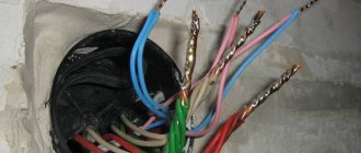
Wiring is laid between the nodal points (where the boxes are installed). Since the installation is hidden, the walls are grooved for the cable, and the boxes are installed on alabaster. The prepared wires are removed from the installed boxes for connection. The length of the free ends should provide the possibility of connection without interference, and allow for 2-3 alterations (with cutting off the used conductors).
The method of connection does not matter (soldered twist in the illustration), the main thing is to understand the principle itself. For cables, the flush-mounted boxes have marked holes. In this case, tightness is not required; there will be a wall and plaster around it. The secret is that alabaster, diluted to a creamy consistency, when installing the box, fills all the cracks, grooves and extra holes.
The result is a monolith with dielectric walls. The planting depth is calculated taking into account the thickness of the wallpaper and the shape of the lid.
Outdoor installation
The principle of connecting the wiring is the same, but the installation is done differently. First, the junction boxes are installed, then the external cable is connected to them. Since the housing provides protection from dust and moisture, the cables are routed inside using sealing clamps.
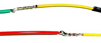
For outdoor installation, collet clamps are used.
The wires must be color-coded: in single-phase versions, zero, phase, and protective grounding. It is not possible (especially before connecting the ends of the cable) to hang tags indicating the purpose of the wires. After final installation, it is enough to record the purpose of the wires on the diagram. You can stick short symbols on the inside of the cover for ease of further maintenance.
If the methods of how to disconnect a distribution box on a power line are clear: we simply connect the input and output wires by color, then connecting a switch is a completely different scheme.
Various ways to connect switches and lighting fixtures
- Classic connection using a junction box.
The neutral and phase wires are inserted into the box. For simplicity, we will leave protective grounding out of brackets. The neutral wire is directly connected to the lamp. The phase is supplied to the switch, then transits through the box and connects to the second input of the lamp. From an installation point of view, 3 two-core wires enter the junction box. Using the same principle, two or three-key switches are connected. Only more transit phase wires (from keys to lamps) will pass through the box. If you connect several lamps to one switch, there is no point in installing several distribution boxes. You can connect lamps in parallel, starting from the first lamp. In this case, the switch will be a group switch. - Wiring for a lamp without junction boxes.
In this case, a power cable is inserted from the nearest distribution box into the switch housing. The neutral wire is connected to the lamp directly, and the phase wire is opened by a switch. On the one hand, this saves one box. On the other hand, the cable is laid irrationally and must be inserted into the switch housing from below or from the side. While according to the standard generally accepted scheme, the main line runs along the ceiling. And from the ceiling junction boxes, the wiring goes down to the sockets or switches.
Connecting switches
The input wires are connected to the switches according to the principle of similarity. There are 2-3 wires from the power source. Each of them is responsible for phase supply, disconnection and grounding.
Accordingly, when connected, they will connect like this:
- shutdown to shutdown;
- ground to ground;
- summing up to summing up;
There is nothing complicated about connecting an outlet. The principle of color similarity, phase and working zero determination also works here. Each color corresponds to the color of the opposite contactor.
Methods for connecting wires in junction boxes
Putting the wires inside the box is half the battle. Now you need to choose a connection that is reliable and easy to maintain.
All cable line connections are divided into two main categories:
- Detachable, that is, the wiring can be disconnected and reconnected many times, without critical damage to the wire or connecting device. For example, a screw connection on terminal blocks.
- One-piece, that is, when the conductors are separated. the connection is destroyed. There is no big problem with this, it’s just that the cable gets shorter each time, and the connecting devices have to be purchased again.
The type of splicing when disconnecting boxes is selected based on the design of the overall network. If you plan to periodically disconnect one or two branches from a common box, it is better to choose a screw connection or reusable quick-release terminals.
For permanent connections that will not be dismantled for many years, the same terminals are used, only for one-time use. Despite the obvious drawback: the impossibility of reuse, such terminals provide more reliable contact compared to reusable ones.
Important! The listed methods allow you to install cables using different conductors: for example, aluminum and copper. In this case, the metals do not touch, and electrocorrosion does not threaten loss of contact.
If you use only copper conductor both in the backbone network and in subscriber branches, there are cheaper ways to permanently connect the wires:
- Twisting with welding. Creates reliable contact, without the risk of sparking and heating of the wiring under heavy load.
The connection is simple, but requires special equipment. As a last resort. You can melt the copper tips with a portable gas torch. - Twisting with soldering. It is not as reliable as with tip reflow, but when using refractory solders, the connection practically does not lose strength, even when heated.
The advantage is accessibility. A powerful soldering iron is easier to find than welding equipment. The basic rule: strength is ensured by twisting; we simply fill the voids with solder, improving contact. - Twisting with mechanical fixation (crimping). A questionable method, since there is a possibility of damage to current-carrying wires.
- There is nothing to say about ordinary twisting: although it is not prohibited, this technique is practically not used.
Direct connection (disconnection)
Is it possible to organize electrical wiring without junction boxes? When branching no more than 2 lines, it’s easy. Several conditions must be met:
- If the connection is made by twisting, soldering with refractory solder is required. Crimping can be used.
- "T" shaped connections are undesirable; it is better to make a "Y" shaped branch.
- After connecting and checking the quality of contact, the splice area must be carefully insulated and protected from moisture. Especially if the connection is made in hidden wiring (plaster wall) or on the street.
Video description
In the video, a specialist explains how to correctly design the location of distribution boxes:
Work begins with the formation of grooves (if hidden wiring is planned), distribution of wires and points of electricity consumption. To prevent confusion in the future, each conductor is marked. For example, introductory, for light, for sconces, for a kitchen or an outlet.
The connection rules look like this:
- the cross-section of the cores is observed depending on the purpose of the specific cable (from the panel - 4 sq. mm, for the lighting network - 2.5 sq. mm, for unloaded sockets 1.5 sq. mm is enough);
- connections are made in series based on a specific type of conductor (neutral, phase or ground);
- The contact between copper and aluminum is formed using special connectors.
After inserting the necessary wires into the holes, the box is fixed. Inside, the ends should be 5-7 cm long. The veins are exposed by about 10 mm. Connections are formed in accordance with the diagram using terminals, clamps, twists, and soldering.
An example of the formation of contact connections and their distribution in a box Source rusenergetics.ru
Everything is neatly distributed throughout the interior of the box. Installation ends with fixing the cover or frame from the socket or switch.