Published: 01/29/2012 Category: Electrical Views: 62703
Installation of hidden electrical wiring
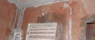
Installation of hidden electrical wiring begins at the stage of repair or construction, when there is nothing but rough walls and ceiling. This is the best option - there is no need to make grooves and then cover them with plaster. The thickness of the plaster layer that will cover the cable with this option should be at least 6–7 mm. In this case, the plaster will cover the wire without any difficulty. However, this thickness depends on the wall.
If the surface is flat and the layer of plaster does not exceed 3–4 mm, then this option will not work. Nobody needs extra consumption: by increasing the thickness of the plaster layer by 3–4 mm, you will make the material consumption for the apartment very significant. It’s easier to first plaster the wall and then groove the partition along it to the required depth.
Attention! Before installing cables and wires, you must check them for integrity using an indicator or test lamp. The same procedure is repeated after installation.
In any case, the lines along which the cable will pass are initially drawn. The distance to which the wires will be spaced is measured from the ceiling or floor. It should be taken into account that this value can be reduced depending on subsequent work, for example laying a floor or installing a suspended ceiling.
It’s good to draw lines using a long building level - it will turn out not only even, but also straight. A distance of 15 cm must be measured taking into account subsequent changes, otherwise it may later turn out that the desired wire ends up behind the ceiling or floor. Then points are placed along the lines where the cable will be attached to the wall. Depending on the type of wire (flexible or monolithic), the fasteners can be at a distance of 40 cm (for flexible) or 20–30 cm (for monolithic).
| Step one: before starting work on installing hidden electrical wiring, you need to draw the location of the boxes and grooves directly on the wall | Step two: using a hammer drill, cut holes for the boxes and use a wall chaser or grinder to make grooves between them |
| Step three: the hatches in the installation boxes are broken out, then the wires are inserted into the holes and secured with plaster or plaster | Step four: after the boxes are tacked, you need to measure the sections of cable and pipes (if they will be laid) and insert the conductors into the grooves |
| Step five: the laid electrical cable and installation boxes are covered with plaster | Step six: after the plaster has dried, you can install sockets and switches |
It is necessary to say a few words about fasteners. Ideal for concrete and brick walls is a dowel-clamp, or, in common parlance, a hanger (UW). To install a cable with a cross-section of 3 x 1.5 or 3 x 2.5, fasteners marked 5/10 are used. For this size of a hole, a drill with a diameter of 6 mm and a length of 60 mm is required. After this, you need to drill holes at the attachment points using a hammer drill. You need to wrap the cable with a dowel and simply insert it into the hole you made to the desired depth. The plastic antennae of the fastener will jam, and the wire will be securely stuck to the wall in one movement. This is much easier than using other types of fasteners.
When making a 90° turn, remember that it must be smooth and no less than specified in the cable specification. Basically, in home wiring, a bend equal to 6 cable diameters is made. Before pressing the conductor with a hook, you need to unwind 10 m from the coil. Then straighten it by hand so that the cable is free of twists and bends - this will significantly simplify installation. Having brought the cable to the electrical point, leave a tail 15–20 cm long. After the cable is secured with hooks, you can begin plastering the walls and further repairs.
Marking installation locations for wiring elements
Option for a plan for placing electrical wiring elements in an apartment project
Regardless of what material the walls of the buildings are made of, a project is drawn up for all buildings, which indicates the electrical supply diagram with the locations of all wiring elements:
- Distribution boards;
- Distribution boxes;
- Socket boxes for sockets and switches;
- Places for installing lighting fixtures (chandeliers, shades).
Based on this plan, the installation locations of all elements and the route for laying wires are marked on the walls with a marker or a carbon or graphite rod.
In addition, the power supply diagram indicates:
- Power of circuit breakers on each group in the network;
- Wire type;
- Wire cross-section;
- Distances between individual wiring elements, between distribution boxes, to sockets and switches. From the switchboard to the first distribution box and connection points for high-power household appliances, to which separate lines are laid (heating boilers, electric stoves, pumps, etc.).
This information can be used to calculate the required length of wires of each type, taking into account the cross-section. The choice of wire cross-section is made using a separate method, which requires detailed consideration; we will proceed from the data specified in the design documentation.
Basic documents
Electrical installation rules apply to both government agencies and private developers. In accordance with their provisions, the initial stage of work should be a well-designed wiring diagram in an apartment in an apartment building. The paper must be approved by the management company that issues the Technical Specifications.
The standards for laying electrical wiring in residential premises are regulated by the following acts:
- Rules for electrical installations (PUE) - planning and installation, connections and switching, use of materials.
- GOST 31565-2012 - fire safety, fire prevention.
- GOST 50571.15-97 - rules for laying lines, installation methods on various surfaces.
- SP 256.1325800.2016 - grounding and safety, insulation and dimensions.
- SNiP 31-110-2003 - placement of devices, distance and installation locations.
Violation of the rules for laying wiring in an apartment entails administrative and financial liability.
Brands of wires laid in walls
The characteristics of wires laid along the walls of various structures depend on many factors:
- Functional purpose of the building;
- Equipment operating conditions;
- On the type of building materials from which the walls are built;
- Requirements of the PUE and other governing documents defining the rules for the design of electrical installations.
Taking these requirements into account, manufacturers make various brands of wires; PPV is considered one of the most popular wires by consumers.
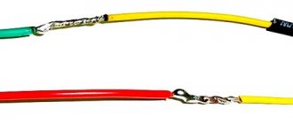
PPV is a wire with a flat configuration, where the cores are placed in one row, and has an insulation layer on each core. The cable is designed to supply power to electrical outlets and lighting networks and can withstand voltages up to 450.
Appearance of PPV with three cores
For laying in walls in residential premises, grades with a cross section of up to 6 mm2 are used. In standard packages, coils are wound in 100; 150; 200m, permissible operating temperature from -50 to +70 ̊С.
VVG - the wire has several models; there is a flat design, similar in appearance to PPV, with double insulation.
Appearance of flat VVG with three wires
There are designs of round, square and triangular shapes.
| VVG brand cables with round cores | ||||
| Number of cores and nominal cross-section (mm²) | External diameter (mm) | Weight of 1 km cable (kg) | ||
| 660V | 1000V | 660V | 1000V | |
| 2:1,5 | 7,5 | 8,1 | 71 | 80 |
| 2:2,5 | 8,2 | 9,6 | 95 | 116 |
| 3:1,5 | 8,1 | 9,4 | 92 | 116 |
| 3:2,5 | 9,3 | 10,2 | 136 | 150 |
| 4:1,5 | 9,2 | 10,1 | 127 | 142 |
| 4:2,5 | 10,1 | 11,0 | 171 | 186 |
| 4:4 | 11,7 | 13,1 | 243 | 273 |
| 4:6 | 13,1 | 14,1 | 325 | 357 |
Table of dimensions of external diameter and weight of VVG wires
Some products contain combustion-preventing additives in the insulation; such wires are marked VVGng.
Cable (NYM) NUM is an analogue of the German wire DIN 57250, flexible, with stranded wires or with a rigid monolithic wire, ideal for hidden wiring in walls in residential premises. This is justified by the composition of non-combustible insulation with reduced emission of toxic gases. The round design has three layers of insulation on each wire, an intermediate layer of chalk-filled rubber and an outer, non-flammable polyvinyl chloride sheath.
Flat installation wire PUNP is the most common and affordable cable in retail chains. Flat-shaped with double PVC insulation, the design can have up to 5 wires.
Tip #1. Experienced electricians do not recommend using PUNP for wiring due to poor quality. Statistics show that 60% of fires due to poor-quality wiring occurred in networks with PUNP wire. 80% of the products on the market are of poor quality, many manufacturers do not comply with technology, the discrepancy is revealed by many parameters:
- Insulation thickness and composition;
- Wire alloy composition;
- Section of veins;
It is safer to buy a more expensive cable and be sure of safety.
What are the advantages of hidden wiring
To begin with, pay attention to the following: hidden wiring in a frame house or apartment implies destruction of the cladding on the walls and ceiling, the floor surface may be damaged, so you should think about the need for its installation or partial replacement every time a major renovation of the room is carried out. It is much more convenient to carry out the process at new facilities.
The main advantages of organizing hidden cable routing:
- All parts of the system are hidden under a facing layer of plaster or plasterboard sheets, so the appearance of the premises does not deteriorate.
- A high level of fire safety, provided that the walls are made of concrete or other material that does not support combustion. Even if ignited, the fire will not spread, since there will be no oxygen or flammable atmosphere in the walls.
- The cable hidden in this way is well protected from ultraviolet radiation and mechanical shock, which increases the service life of the entire system.
With hidden wiring, the appearance of the walls does not deteriorate.
The disadvantages of this method are primarily related to the complexity of installation, the need to destroy walls and the difficulties that arise when repairing and maintaining the wiring. The cable and other elements are hidden under a layer of plaster, so if necessary you will have to remove it every time. All this cannot be said about electrical systems equipped in an open way.
However, hidden wiring is the most relevant, reliable, safe and correct solution for any permanent housing. In log houses, garages, bathhouses and similar buildings, you can use open electrical wiring.
Exposed retro wiring in a wooden house
Wire selection criteria
First of all, you need to be guided by the project, which takes into account both the brand of the wire and its cross-section, taking into account the operating conditions of the room. If a suitable wire is not available, an analogue or a product that meets the technical specifications is installed.
In most cases, PPV can be replaced by VVG; flat wires are often installed under plaster on concrete and brick walls. They fit securely to the surface and do not require a thick layer of plaster to hide the network.
Tip No. 2 For lighting networks in areas from the junction box to the chandelier or hanging lampshade, it is recommended to use flexible stranded wire. At the point where the contacts are attached to the lighting fixture, the section of the circuit is mobile and rigid wires can break off; in this case, flexible wires last much longer.
According to the requirements of the PUE, in rooms with high humidity, wires with rubberized insulation are installed with moisture-proof properties of all elements with a degree of at least IP 54. As a rule, such wires have a round shape and, before laying, punch grooves in brick or concrete walls. In wooden log houses they are placed in a non-flammable corrugated pipe.
For operation in conditions of high humidity, the following wires are used:
- NUM;
- PRTO is laid in fireproof pipes;
- PR – universal wire, can be used in dry and wet conditions.
Installation of open electrical wiring
Open type wiring Installation
of open electrical wiring is carried out in buildings made of wood, panels, panels and other flammable materials. When designing, you need to take into account that the distance of wiring from the ceiling should be at least 2 cm, and floor sockets - no more than 1 meter. When laying lines, it is prohibited to use nails, staples and screws to secure the cable directly to the load-bearing surface.
Regulatory documents establish the following installation options:
- flexible corrugated tubes;
- rigid round and rectangular plastic profiles;
- metal hoses with threaded connections;
- polymer cable channels;
- hollow detachable platbands and baseboards;
- steel strings;
- ceramic insulators.
Since such structures look unaesthetic on the ceiling, there are several ways to disguise them. For this purpose, tension structures, suspension systems made of gypsum plasterboard, plastic panels and metal slats are used.
Laying wires in plasterboard walls
The design of plasterboard walls provides a large number of screws for fastening various elements. Therefore, special attention is paid to the wiring method so as not to damage the insulation and short circuit the wires.
Plasterboard sheets are attached to a pre-assembled frame made of galvanized metal guides.
Diameter size chart for plastic corrugated pipes
| Outer surface diameter (mm) | Inner Surface Diameter (mm) |
| 16,0 | 10,7 |
| 20,0 | 14,1 |
| 25,0 | 18,3 |
| 32,0 | 24,5 |
| 40,0 | 31,5 |
| 50,0 | 39,6 |
To lay wires in such structures, technological holes are provided in the metal profile; the wire must be laid in non-flammable plastic corrugated pipes.
The pipe and wire are laid in the hollow part of the wall after attaching the drywall to one side of the partition or after attaching the profile to the load-bearing wall.
An example of piercing a wire and a corrugated pipe with a self-tapping screw
In this case, the places with the sharp ends of the self-tapping screws are rounded, and before fastening the plasterboard sheets, on the other side of the frame, the cable passage zone is marked, into which the fastening elements are not screwed.
Socket boxes for mounting in hollow plasterboard walls
To install socket boxes and distribution boxes, holes of the appropriate diameter are drilled using an electric drill with drywall bits. The plastic cups of the socket boxes have a special design with strips that press the body to the plane of the wall from the inside. To do this, screw the clamping screws clockwise until they stop. The wires are inserted into the technological holes of the socket boxes 15-20 cm to the outside for cutting and connecting sockets and switches.
An example of installing a socket box in a wall
In the same way, wires are laid and socket boxes are attached in walls made of plywood, chipboard and OSB, in any structures with a hollow interior. To drill holes in wooden sheets, appropriate crowns and other elements are used.
Features of electrical wiring in the floor
Preferred areas of use.
Laying cables in the floor is most appropriate for new construction when the room is in “bare walls” condition, i.e. in fact, in new buildings (as shown in Figure 1). This allows you to minimize the time and effort required to carry out electrical wiring due to the large free space and the ability to eliminate the need for wall chiselling.
Figure 2 shows that this provides the greatest benefit in the area near the central distribution panel.
Rice. 1. Formation of a system of underground channels at the rough finishing stage
Rice. 2. Inserting corrugated tubes into the central electrical panel
For wooden houses in which the floorboards are laid on massive joists, there is enough free space for the channels of the type in question along with the distribution boxes. This allows this type of wiring to be used also during major repairs.
Rules for forming channels and pulling cables.
When forming channels, it is advisable to minimize the number of turns. Although current regulations allow two or even three turns, it is advisable to perform no more than one.
The maximum length of a straight section should not exceed 15 m.
When laying several channels, they should be placed in parallel; when turning, intersections are not allowed (this rule is shown in Figure 2).
Rice. 3. Rules for parallel laying of several channels
An example of improper planning of a canal system with a large number of intersections is shown in Figure 4.
Rice. 4. Incorrectly planned canal system with a large number of intersections
It is advisable to leave a long cord made of wire, cable or plastic rod in the laid channel, which is used to tighten the cables.
To facilitate pulling and replacing wires, they should not fill more than 50% of the channel cross-section “in the clear” (0.6 of the pipe diameter).
To minimize the forces applied to the cable when laying in a non-linear channel, its direction should be chosen so that the turn is closer to the beginning of the channel, and not to its end. This situation is shown in schematic form in sketch Figure 5.
Rice. 5. Rules for choosing the direction of pulling cables in pipes with turns
Laying wires on brick and concrete walls without gating
In these cases, it is very convenient to use flat-shaped wires. Along pre-marked routes, the wire is attached to the walls with plastic staples with high-strength nails or plastic dowels with clamps. Previously, fastening was carried out with tin plates, which were screwed to the wall with self-tapping screws onto a plastic dowel or simply aimed at the wall with a construction gun.
For socket boxes and distribution boxes, holes are drilled using a hammer drill with special concrete bits. The body of the socket box is inserted into the hole and attached to the gypsum mortar; before this, wires are inserted into the side technological holes.
Tip No. 3 It is recommended to drill holes for socket boxes after the surface of the wall with the wiring lines is plastered. This technique will ensure that the top edge of the socket cup is installed at the same level with the wall surface.
If you install the socket box earlier, it will be difficult to achieve a clear match of the levels, and differences lead to problems when installing sockets. If the socket box is deeply recessed, the bolts securing the front panel of the socket may not reach the threads on the body. If the socket box protrudes, there will be a gap between the wall and the front panel.
Distribution boxes and socket boxes are manufactured according to certain standards. The diameter and depth are selected depending on the size of switches and sockets; for distribution boxes, the number of wires that are inserted into it is taken into account. If there are a large number of wires with a large cross-section and the outer diameter of the cable of a round structure, it is recommended to make grooves in the walls.
Hidden wiring device
Hidden wiring can be done using two methods. The first, classic option is to place cables and network elements inside the grooves or under the casing. The second option, which has been gaining popularity recently, is the use of special pipes and cable ducts. In fact, the wires are hidden from view, but not located inside the wall.
Wiring can definitely be called hidden only in the first case, when the cable is hidden inside building structures. The latter include partitions, various ceilings, floors, walls and ceilings. In most cases, this option involves making special grooves. To make them, use a wall chaser or grinder, but you can get by with a hammer drill or a scarpel with a hammer. The same pipes and channels from the second method should also be present in the first: they are laid in grooves to increase the protection of the wires.
Laying wires in grooves
Attaching cable ducts to the surface of walls and ceilings and then placing wires inside is more of a method of organizing open electrical wiring.
Laying grooves in concrete and brick walls
The grooves are punched to a depth of 1-2 cm with a hammer drill in impact mode with an attachment in the form of a chisel. Closer to the sockets and distribution boxes, the grooves are made a little deeper, up to 3 cm, so that the wires fit freely into the technological holes of the socket cup.
Outer diameter and weight of cable (KG)
| Section | Diameter (mm) | Weight of 1 km cable (kg) |
| 1:16 | 12.3 | 288 |
| 1:25 | 15.3 | 460 |
| 1:35 | 16.5 | 568 |
| 1:50 | 19.0 | 778 |
| 1:70 | 21.8 | 1094 |
| 2:1,5 | 11.2 | 172 |
| 2:2,5 | 12.7 | 224 |
| 3:1,5 | 11.8 | 201 |
| 3:2,5 | 13.4 | 268 |
| 3:1,5+1,5 | 12.7 | 223 |
| 3x2.5+1.5 | 15,5 | 350 |
| 3x4+2.5 | 16,8 | 437 |
| 3x6+4 | 18,5 | 641 |
The width of the groove is made taking into account the number and size of wires laid in this area.
The wires are fastened in the same way as when laying without grooves. After laying the wires, they are covered with a layer of plaster.
Grooves in a concrete wall, cut with a grinder using a concrete disc and processed with a hammer drill and chisel. The photo also shows the fastening of wires to plastic clamps with dowels.
In installation organizations where gating is carried out in large volumes, industrial wall chasers are used. This tool allows for adjustment of the depth and width of the groove; some models provide for dust removal with a vacuum cleaner. The productivity of wall chasers is much higher than when working with a conventional hammer drill, the channels are more even, but the price is high, and it is not advisable to use it for one-time work.
Main points of requirements and rules
Table of cable cross-sections by power
Rules for laying electrical wiring cover a wide range of aspects of installation, from the selection of materials to the procedure for putting the structure into operation.
Minimum cross-section of cable cores:
- introductory - 4 mm;
- sockets - 2.5 mm;
- lighting group - 1 mm.
Number of conductor cores:
- single-phase line - 2;
- single-phase network with grounding - 3;
- two-phase supply - 3;
- two-phase network with grounding - 4.
Placing sockets, switches and electrical wiring at a distance from surfaces and objects:
- floor - 30-120 cm;
- panel joints - 20 cm;
- window and door openings - 10 cm;
- sewer and water pipes - 30 cm;
- sinks, bathtubs - 50 cm;
- heating devices - 20 cm;
- electric stoves - 15 cm;
- gas lines - 40 cm.
Types of wiring:
- with insulation of one or several colors;
- copper and aluminum;
- with regular and non-flammable coating.
Circuit breakers that are installed in the electrical panel:
- batch type;
- relay;
- fusible;
- electronic.
Line layout diagrams:
- sequential;
- parallel;
- combined.
Requirements for the installation of electrical wiring apply to residential and auxiliary premises, including loggias, balconies and vestibules.
Tools and attachments used when laying wires in walls
Grooves and holes for socket boxes can be punched with an ordinary hammer and chisel, but in the 21st century, this is done only for small volumes in the absence of power tools or from feeble minds, for sporting interest.
A hammer drill is a universal tool. It can be used as a drill for drilling wood and drywall; in perforation mode, you can drill concrete and brick walls and punch grooves.
Drills with variable speed control are used for drilling only wooden and plasterboard surfaces, as a screwdriver with appropriate attachments. The speed is set depending on the material being processed; more for wood, less for metal.
Attachments for drills and rotary hammers come in a wide variety of designs and purposes:
- Conventional drills for wood, metal, with Pobedit diamond tips for drilling concrete and brick;
- Crowns for drilling wooden and plasterboard sheets;
Drill bit for drilling wood or drywall
- Crowns with tungsten, diamond and pobedit teeth, for drilling brick and concrete walls;
Crown with pobedite teeth for drilling holes for socket boxes in brick and concrete walls
- Titanium tetrahedral bits with tungsten coating for screwing in self-tapping screws.
Tip No. 4 When buying tetrahedral bits, do not save money by buying cheap Chinese metal products, they wear out quickly.
When hidden wiring is not acceptable
First you need to understand the two main types of hidden electrical wiring. It can be non-replaceable, embedded in the wall or replaceable (in pipes placed in the wall). Serious difficulties arise when installing the system inside a concrete wall. The process is accompanied by gating, but in panel houses there are special restrictions on this. It is much easier to make grooves for wires in a brick wall: it is easy to cut, the cable is conveniently attached inside such grooves.
The permissibility of installing hidden wiring is regulated not only by electrical safety rules, but also by building codes. For example, it is strictly forbidden to groove a single brick of the M-150 brand, since this process will lead to the destruction of the corrugated part of the material. It is also prohibited to place hidden wires inside log houses.
Hidden wiring on combustible bases is prohibited
Mistakes when laying wires in walls
- When laying wires in concrete or brick walls without grooves, they forget to make a short groove near the distribution boxes or socket boxes. This is necessary so that the wires fit freely into the technological holes in the lower part of the glass.
An example of a groove entering a hole for a socket box.
If you insert a wire through the top or make a hole in the upper part, there is a risk of a short circuit or breakage. When installing the socket, its body will tear the insulation or crush the wire ;
Correct entry of wires from the bottom of the socket box
- You should not install wires on lighting and socket groups with a larger cross-section than specified in the project, usually 2.5mm2. With a cross section of 4-6mm2, the cores are difficult to place in the contact group of a socket or switch, especially when the alloy is hard and elastic. Sometimes in such cases, under the elasticity of the wires, the contact groups break, and the ceramic or plastic case bursts.
- In order not to make a mistake in the width and depth of the groove in a separate area, add up the width of all the wires that are laid there and make 1 cm more with a margin.
- When drilling with a hammer drill using a drywall crown, do not forget to turn off the perforation mode, otherwise the sheet may simply break in this place.
Pros and cons of this installation
You should not lay a cable in the floor without knowing all the intricacies of this process. And you should start with the advantages of hidden electrical wiring:
- High degree of electrical safety. The floor covering (floorboard, laminate, linoleum) will become the dielectric that will prevent the spread of potential in the event of a cable breakdown. This means that a person will not be shocked by electric current even if he stands in the place under which the cable passes.
- Less spending. High-quality wiring will require less cable, which will provide significant savings.
- Ease of operation. The most difficult stage will be pouring the concrete floor. When installing electrical wiring, you need to insert the cable into the corrugation and simply lay it on the floor. Many electricians do not even attach the corrugation to the concrete base.
But in addition to its advantages, any work also has its disadvantages. The disadvantages of installing cable wiring under the floor include:
- The complexity of identifying and eliminating the malfunction. If the cable breaks down, you will have to lay a new line or dismantle the floor surface.
- Additional expenses for pouring a new floor if dismantling is required. Also included in the category of additional investments is the consumption of corrugation, without which the cable cannot be laid in the floor.