Internet
2020-06-12
172
Reading time: 5 min
NikolaiNikolai
Share
An ADSL splitter ensures the operation of all devices connected to a dedicated telephone line. When transmitting data on the network through an ADSL filter, the speed reaches the following values:
- to the consumer: 1.5 – 24 Mbit/s;
- from the consumer: 640 Kbps – 3.5 Mbps.
Splitters also prevent the occurrence of pulse overvoltage, critical current values that can occur in cables in the event of lightning discharges or faults in electrical wiring.
Let's consider possible options for connecting this device to a home or office network.
How many TVs can be connected to one antenna?
The most common option for everyone is “one screen – one antenna”. However, today you will not surprise anyone with the fact that in one apartment there are two, three or more television receivers. Of course, you can install your own antenna for each of them, but it is much more profitable to connect everything to one common one that transmits a high-quality signal.
Technically, double connection is not complicated: there are special dividers (doubles, tees, etc.), with the help of which one signal arriving through the antenna cable can be divided into several.
With sufficient signal strength and the use of high-quality amplifiers, the number of televisions connected to one antenna is not limited.
When splitting a signal, keep the following in mind:
- Possible loss of power. Under the influence of electromagnetic waves, with the help of which the signal is transmitted, a current arises in the television antenna, flowing through the coaxial cable to the receiving device. However, this current is weak. Any additional resistance leads to losses and ultimately to attenuation. Therefore, when connecting a second TV, you must take into account that the entire system will work either in an area with a powerful TV signal, or you must provide in advance for connecting an amplifier.
- Dividers (also known as splitters) come in different designs. It is important to remember here: a satellite splitter for receiving terrestrial digital television is suitable, but on the contrary, it is not. In addition, there are divisors with and without coordination. Most of the available models sold in stores use conventional capacitive or transformer isolation, which means that it is necessary to provide a place to power the amplifier even before the divider.
- You need to connect two TVs to the same antenna, but to different set-top boxes. Connecting to a single receiver is technically simpler, but it combines the signal so that the same picture will be synchronously broadcast on both screens.
Advantages and disadvantages
The undoubted advantages include the fact that ADSL splitters provide high-quality communication, which is impossible without their use. The older generation of Internet users remembers that previously, any entrance to the World Wide Web was blocked by the phone, strange sounds were heard on the handset, and the connection was restored only after disconnecting from the Internet. Today there are no such problems anymore.
Line parameters for ADSL Internet: signal to noise ratio
The signal standard and protocols have undergone dramatic changes. The modern ADSL connection scheme is adapted for standard communications. But it is not yet possible to completely get rid of interference when all devices use the line simultaneously.
Note! A splitter allows you to be on the Internet and at the same time calmly talk on the phone.
Ignorant people asking the question “what is an ADSL splitter, what pros and cons does it have”, do not fully understand its importance in the communication system. Without it, you will not be able to connect to the telephone line normally. Claims can only arise regarding the quality of execution. It is difficult to include the cost of the device as a disadvantage. It is included in the price of the modem upon purchase.
If it gets out of order, replacing it will not be a blow to the family budget. It's not worth saving on your purchase. A splitter from a reputable manufacturer does not differ much in cost from products of dubious quality. It's better to buy a good model.
Do I need an amplifier?
If you need to connect several TVs to one antenna at once, you need to keep in mind: using a splitter of any design, the signal is still divided in half, and if 3 tuners are connected, then each gets only a third. Therefore, in most cases you need to connect an amplifier.
It will definitely be needed in situations where:
- the signal has good quality, but low power;
- two or more splitters are installed;
- long connecting cables are used.
In addition, the amplifier will most likely be superfluous when using cable and satellite TV. For them, the main thing is not to degrade the incoming signal, and the amplifier inevitably introduces distortion.
Finally, if the signal is critically weak, the amplifier is useless. It will not be able to raise the TV signal received by the antenna to the required level: there is simply nothing to amplify.
Options
The splitter has an ADSL local network specification, a load capacitance for the telephone output, a maximum operating current and pulse current, a certain response time for voltage and current protection, a surge voltage, and a pass resistance. All these parameters are indicated in the instructions. Splitters are usually installed in rooms that are maximally protected from direct sunlight and high humidity. The device weighs no more than forty grams.
Connecting 2 or more TVs to a passive antenna
Passive are those that do not have a structurally built-in amplifier. They receive a signal only due to their shape. If amplification is required, it is provided by an additionally connected external unit.
The easiest way to connect two TVs is to install a splitter with the appropriate number of outputs on the antenna cable.
The best options here would be:
The maximum number of TVs connected using one splitter is 8 using SAH 812F. If a larger number is required, it is necessary to build a circuit of dividers, splitters and at least one amplifier.
Another option for connecting three or more television receivers is to use an active splitter. In this case, the cable from the antenna is connected to a divider that has an amplification stage, and it, in turn, transmits the signal to another passive type splitter.
An active splitter can have a separate input for power or use current supplied from the receiver through the same cable that carries the antenna signal.
Purpose
What are the differences between 3G and 4G networks: features, advantages and disadvantages
When connecting, the ADSL splitter guarantees signal filtering. Without a device, a connected phone can significantly affect the quality of network information transmission. Possible outages and unstable Internet operation. In turn, strong interference also occurs when using the telephone or fax.
It is not recommended to connect the line directly to the computer. This is done to test the connection. The instructions indicate a diagram for connecting the ADSL splitter to the switching network.
We connect 2 TVs to an active antenna
An active antenna is a device in which the amplification unit is its structural part. In this case, it most often receives power via a coaxial cable. You can connect as many TVs as required to such an antenna in two different ways.
Through a divider with matching
The booster unit needs power. However, if you use a conventional divider, the current will not flow to the antenna: there is a transformer or capacitive decoupling. To supply current to the amplifier, you will need a special device - a power divider (Power Pass).
To connect 3, 4 or more TVs to such a divider, you can use active splitters with external power. The connection chain is constructed in this case in the same way as described above for a passive antenna.
Through a regular splitter
If there is no divider with a power pass, current can be supplied in the area between it and the splitter. In this case, a fastener for insertion and a power supply separator are used.
- the required current is supplied to the amplifier;
- The signal goes through the divider to the receivers.
If you need to connect 3 or more TVs, you need to take a splitter with the appropriate number of connectors. The principle diagram is the same.
How to connect
The instructions for connecting the splitter are quite simple:
- select a location and attach the divider to it;
- Next, you need to remove the plug from the antenna splitter (do this operation for each connector);
- use a coaxial cable (adapter) to connect the input to the TV and the jack;
- connect the television cable entering the apartment.
At this point the installation can be considered complete; installation takes no more than 10 minutes.
Bonus: we connect 2 TVs without adapters
According to amateur TV experts, in some cases adapters in the form of dividers are not only unnecessary, but even harmful.
Experts suggest the following scheme:
- An antenna and two coaxial cables are taken.
- The ends are trimmed. The distance at which the top insulation needs to be removed is determined experimentally.
- The braid and foil of the cables are unraveled and a general twist is made from it. The central wires remain separate.
- These two wires are fastened with screws to a regular place in the antenna. A twist of shielding material is attached in the same place where the shield of a single cable should normally be located. The main thing is to ensure that the cores do not come into contact with the screen.
However, it is technologically more difficult, in addition, it changes the characteristics of the circuit in an unpredictable way, so you can use this connection option, but the result is not guaranteed.
Features of connecting to one satellite dish
If the antenna converter has two outputs (for signals with horizontal and vertical polarization), you can connect your own receiver to each of them. Or use a multiswitch divider: both outputs of the converter are connected to it, and it distributes signals to 2-3 receivers. However, here you must keep in mind that you will need to pay separately for channels for each device.
Finally, you can connect two converting units to one dish. Then you can connect your own receiver to each of them. However, you need to remember: you cannot use two converters to receive channels from one satellite. Fortunately, the geostationary orbit is filled quite densely and there will almost always be an additional satellite in the reception area.
When using an RF modulator, the procedure will be as follows:
- The receiver is connected and configured to receive satellite channels.
- An HF modulator is connected to its audio and video outputs, through which low-frequency signals (AV, SCART, etc.) are transmitted. This device converts a low-frequency signal into a high-frequency signal and divides it into several RF outputs. You can already connect regular 75 Ohm coaxial cables to them.
- The cables are connected to the antenna connector of the receivers, which are tuned to the broadcast frequency.
Important! Using an RF modulator, you can connect any number of TVs for which there are enough connectors on the device. However, they will all show one channel. Therefore, this scheme is more often used in bars, cafes, shops, and not in residential buildings.
ADSL splitter
How to connect ADSL splitter correctly
Screenshots are taken from the documentation for ADSL modems ZyXEL, HUAWEI, D-Link, etc. Let's consider the connection option using the ZyXEL AS 6 EE splitter as an example.
Connecting an ADSL splitter.
The most common option. 1. to the LINE of the splitter. Sometimes this connector is called LINE-IN , for example ECI-TELECOM splitters. I haven't seen any other options. Branches or branches are not desirable. This significantly reduces the reliability of the ADSL modem. If there are taps/branches to the splitter, then telephone sets must be turned on through “microfilters”. Instead of a microfilter, you can use another ADSL splitter.
2. to the MODEM of the splitter. In ECI-TELECOM splitters this connector is sometimes called LINE-OUT , in D-Link splitters this connector is called ADSL . SIEMENS calls it NT . (Network Termination)
ADSL splitter ZyXEL AS 6 EE
General option for connecting the ZyXEL AS 6 EE ADSL splitter, using the ZyXEL 660H modem as an example
How to connect ADSL splitter
UTP twisted pair cable, category 5, 2 pairs, solid UTP2-C5E-SOLID-GY
Two-pair cable is ideal for termination under RJ11. For the line, take a blue or orange pair. It is prohibited to take wires from different pairs! Splitters use RJ11 connectors, but in older ECI-TELECOM models and ISDN splitters from ZyXEL, the MODEM was replaced with RJ45. All splitter connectors use two central contacts.
Possible options for connecting an ADSL splitter
Cascade connection. Such a connection is not possible with SIEMENS splitters; their NT/ADSL output is isolated by capacitors. Direct current for a phone connected to the second splitter will not pass.
Cascade connection Using microfilters
By connecting all these endless splitters, microfilters, telephones to the line, you increase the capacitive load on the line. Thus, you yourself are worsening the quality of telephony. A situation may even arise that, due to excessively increased capacitance, the calling signal will no longer pass through the line. Also, the more connections, connectors, contacts, the less reliability.
How not to connect an ADSL splitter
Sometimes they connect a telephone line to the PHONE . Telephone sets are plugged into the LINE . When turned on this way, telephones will work, but the ADSL modem will not work.
The strangest thing is that modem manufacturers indicate in the documentation the incorrect location of the connectors when connecting a splitter. The modem is drawn in every detail, but for some reason the splitter is drawn somehow. Please take this into account.
Source
Instead of conclusions
Connecting two or more TVs to one antenna is a technically difficult task, but it can be solved. It may require the use of additional equipment and calculations. In addition, it is necessary to take into account the existing signal level and quality.
If the antenna is correctly installed and configured, it will receive a high-quality TV signal. And if this is the case, the user may have a question whether it is possible to connect two TVs to it at once. And if you can have 2, then what about three or, say, five? Let's figure out in what cases this is possible and what is required to implement the task.
What is this
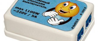
An ADSL splitter is used to separate the voice signal frequency from the frequencies used by the modem. It ensures smooth operation of devices connected to the telephone line. Splitters are equipped with special protection against overvoltage and current that occurs in cables during a thunderstorm. The device is small in size, similar to a rectangular box with three connectors “Line”, “Phone”, “ADSL”. Thanks to it, the modem and telephone can work without interruptions on the same line and do not depend on each other.
Sometimes, instead of this, devices use a microfilter, which is installed at the connection point of the telephone. Schemes are often used in which microfilters are connected simultaneously with splitters. There are two types of ADSL splitter: Annex A and Annex B. ADSL technology is translated and stands for “asymmetric digital subscriber line”, it is high-speed.
How many TVs can be connected to one antenna?
The most common option for everyone is “one screen – one antenna”. However, today you will not surprise anyone with the fact that in one apartment there are two, three or more television receivers. Of course, you can install your own antenna for each of them, but it is much more profitable to connect everything to one common one that transmits a high-quality signal.
Technically, double connection is not complicated: there are special dividers (doubles, tees, etc.), with the help of which one signal arriving through the antenna cable can be divided into several.
With sufficient signal strength and the use of high-quality amplifiers, the number of televisions connected to one antenna is not limited.
When splitting a signal, keep the following in mind:
- Possible loss of power. Under the influence of electromagnetic waves, with the help of which the signal is transmitted, a current arises in the television antenna, flowing through the coaxial cable to the receiving device. However, this current is weak. Any additional resistance leads to losses and ultimately to attenuation. Therefore, when connecting a second TV, you must take into account that the entire system will work either in an area with a powerful TV signal, or you must provide in advance for connecting an amplifier.
- Dividers (also known as splitters) come in different designs. It is important to remember here: a satellite splitter for receiving terrestrial digital television is suitable, but on the contrary, it is not. In addition, there are divisors with and without coordination. Most of the available models sold in stores use conventional capacitive or transformer isolation, which means that it is necessary to provide a place to power the amplifier even before the divider.
- You need to connect two TVs to the same antenna, but to different set-top boxes. Connecting to a single receiver is technically simpler, but it combines the signal so that the same picture will be synchronously broadcast on both screens.
Purpose and main differences
Splitters allow you to evenly divide a television signal between several outputs. For example, if the input signal level was 12 dB, then at the outputs of a double divider it will be 6 dB, a triple divider - 4 dB, and a quad divider - 3 dB.
Double splitter
The figure shows a schematic representation of a double splitter, where:
A – signal input;
B and C are the exit.
Antenna splitters of this type are used in cases where it is necessary to send a signal to 2 or 3 TVs, or more if the device has an amplifier (active splitter). An example is the model of the Polish manufacturer ARA-01A.
Diplexers allow you to combine two signals into one. Most adder models are universal; they can work in two directions, that is, act as an adder or a divider.
Dual diplexer
The figure shows a schematic representation of a double diplexer, where:
A and B – input signals;
C – output signal.
A diplexer is used in cases where it is necessary to run a signal from a satellite and a conventional antenna over one cable or combine signals from different ranges. The figure shows an example of using an adder and a divider together, where:
- A – television antenna;
- B – satellite dish;
- C – adder;
- D – socket with a built-in divider for connecting two television cables.
Scheme of joint use of an adder and a divider
. Taps are used to organize a backbone television network, for example, to divert a signal to apartments in a multi-story building.
Highway organization diagram
The figure shows an example of organizing a highway using several taps, where:
- A – incoming signal;
- B, C, D, E, F, G, H, I, J – signal output (tap), for example, to each floor of a nine-story building.
As can be seen from the connection diagram, such devices have one pass-through output, from which the signal is supplied to the input connector of the next coupler.
Video: TV antenna splitter.
Antenna splitters can also include a range blocker (stub), which is widely used by cable television operators to separate social and paid connection packages.
In everyday life, splitters are most often used; they are used to connect several televisions to the antenna cable entering the apartment; the quality of the television signal directly depends on these devices.
Do I need an amplifier?
If you need to connect several TVs to one antenna at once, you need to keep in mind: using a splitter of any design, the signal is still divided in half, and if 3 tuners are connected, then each gets only a third. Therefore, in most cases you need to connect an amplifier.
It will definitely be needed in situations where:
- the signal has good quality, but low power;
- two or more splitters are installed;
- long connecting cables are used.
In addition, the amplifier will most likely be superfluous when using cable and satellite TV. For them, the main thing is not to degrade the incoming signal, and the amplifier inevitably introduces distortion.
Finally, if the signal is critically weak, the amplifier is useless. It will not be able to raise the TV signal received by the antenna to the required level: there is simply nothing to amplify.
ADSL splitters for the Internet: what they are, device and circuit
Transferring information to the Internet requires the correct configuration and installation of communication routes. When connecting to a standard telephone line, the recommended circuit diagram and suitable system components must be followed. Stable operation of all devices is impossible without proper connection.
An ADSL splitter guarantees high-quality signal separation into two streams. One is supplied via a modem to a computer or router. The other provides telephone communication independent of the Internet connection.
Connecting 2 or more TVs to a passive antenna
Passive are those that do not have a structurally built-in amplifier. They receive a signal only due to their shape. If amplification is required, it is provided by an additionally connected external unit.
The easiest way to connect two TVs is to install a splitter with the appropriate number of outputs on the antenna cable.
The best options here would be:
The maximum number of TVs connected using one splitter is 8 using SAH 812F. If a larger number is required, it is necessary to build a circuit of dividers, splitters and at least one amplifier.
Another option for connecting three or more television receivers is to use an active splitter. In this case, the cable from the antenna is connected to a divider that has an amplification stage, and it, in turn, transmits the signal to another passive type splitter.
An active splitter can have a separate input for power or use current supplied from the receiver through the same cable that carries the antenna signal.
Price overview
As an example, we chose the Luxmann SP-202 splitter, which allows you to connect two TVs to one antenna cable.
| City | Cost (USD) | City | Cost (USD) |
| Ekaterinburg | 4 | Penza | 4,2 |
| Krasnoyarsk | 4,1 | Minsk | 4,1 |
| Moscow | 3,8 | SPb (Petersburg) | 3,85 |
As can be seen from the table, the price of an antenna splitter in Moscow, Krasnoyarsk, Minsk and other cities does not vary much. How economically profitable it is to make it yourself or buy it is up to you to decide.
Bonus: we connect 2 TVs without adapters
According to amateur TV experts, in some cases adapters in the form of dividers are not only unnecessary, but even harmful.
Experts suggest the following scheme:
- An antenna and two coaxial cables are taken.
- The ends are trimmed. The distance at which the top insulation needs to be removed is determined experimentally.
- The braid and foil of the cables are unraveled and a general twist is made from it. The central wires remain separate.
- These two wires are fastened with screws to a regular place in the antenna. A twist of shielding material is attached in the same place where the shield of a single cable should normally be located. The main thing is to ensure that the cores do not come into contact with the screen.
However, it is technologically more difficult, in addition, it changes the characteristics of the circuit in an unpredictable way, so you can use this connection option, but the result is not guaranteed.
Features of connecting to set-top boxes
If you use receivers or tuners, you can connect a second TV in two ways. Which one is suitable depends on the design of the receiving equipment.
If at least one of the receivers has an RF-OUT connector, the connection is made as follows:
- The first receiver is connected to the antenna via a regular cable and the corresponding socket on the case.
- The second receiver is connected to the first. To do this, its design must provide the ability not only to connect to an antenna, but also to relay the signal. As a rule, in such set-top boxes the output jack is marked as “RF Out” or similar.
Important! When using two receivers, in order to watch not only free, but also encrypted channel packages, you will have to purchase two smart cards and pay a subscription fee for both sets of equipment.
If none of the receivers has a jack for an output signal, you will have to purchase a divider. Installation using a splitter generally looks like this:
- the antenna cable from the dish is connected to the divider;
- each of the receivers is connected to the corresponding output jack of the splitter using a similar shielded cable;
- Each receiver is independently configured for reception.
How to choose
First of all, it should be taken into account that the operating frequency of antenna splitters for digital television and satellite dishes is different. For the former it is limited to 1 GHz, for the latter it is 2.5 GHz. In addition, the satellite splitter may have a “Powerpass” function (allows you to supply power to the satellite dish head).
Note that a satellite splitter can also be used to split a digital or analog signal.
The second parameter that you should pay attention to is signal attenuation; as a rule, its value is indicated on the device body; the lower it is, the lower the losses.
It is also important who the manufacturer of the device is. Products from such well-known manufacturers as: Lans, Rexant, Premier, TAH, Luxmann, Alda, Hama, Sat, etc. will give an output signal an order of magnitude better than Chinese or homemade splitters.
Features of connecting to one satellite dish
If the antenna converter has two outputs (for signals with horizontal and vertical polarization), you can connect your own receiver to each of them. Or use a multiswitch divider: both outputs of the converter are connected to it, and it distributes signals to 2-3 receivers. However, here you must keep in mind that you will need to pay separately for channels for each device.
Finally, you can connect two converting units to one dish. Then you can connect your own receiver to each of them. However, you need to remember: you cannot use two converters to receive channels from one satellite. Fortunately, the geostationary orbit is filled quite densely and there will almost always be an additional satellite in the reception area.
When using an RF modulator, the procedure will be as follows:
- The receiver is connected and configured to receive satellite channels.
- An HF modulator is connected to its audio and video outputs, through which low-frequency signals (AV, SCART, etc.) are transmitted. This device converts a low-frequency signal into a high-frequency signal and divides it into several RF outputs. You can already connect regular 75 Ohm coaxial cables to them.
- The cables are connected to the antenna connector of the receivers, which are tuned to the broadcast frequency.
Important! Using an RF modulator, you can connect any number of TVs for which there are enough connectors on the device. However, they will all show one channel. Therefore, this scheme is more often used in bars, cafes, shops, and not in residential buildings.
Specifications
Review and configuration of the D-Link Dir-320 modem
ADSL splitter is a unified device. There is no need to configure it. A simple electronic circuit allows you to filter the signal in two directions - telephone in the range of up to 3-5 kHz and the Internet - from 20 to 50 kHz. The supported standard is called Annex A. The connectors for 1 input and 2 outputs are the same - RJ-12. The circuits are assembled from original parts with manufacturer's markings.
Note! Splitters are repaired only when there is a broken contact. Parts can only be replaced from the same model, which is practically not done in practice. It is inexpensive and easier to buy.
Instead of conclusions
Connecting two or more TVs to one antenna is a technically difficult task, but it can be solved. It may require the use of additional equipment and calculations. In addition, it is necessary to take into account the existing signal level and quality.
TV crab
(splitter, combiner, splitter) is a radio device designed to connect several receiving devices (TVs, video recorders) to one or more television signal sources (cable network, ordinary or satellite antenna).
I came across a homemade splitter that I made when the first VCRs appeared, and it became necessary to watch one program on TV and simultaneously record another. Back then the word crab was not used, and such devices were called “TV signal splitters.”
The design of the splitter is a flat box with four threaded axle boxes riveted at the corners. The top of the box is closed with a lid made of a sheet of foil fiberglass with four screws. The cover can be made of any metal, iron, brass, thus ensuring shielding of the splitter parts.
Three standard old-type television connectors are secured to the cover using M2.5 screws and nuts. The radial leads of the connectors are soldered directly to the cover. Thus, they are connected to each other and electrical contact with the screen is ensured.
The splitter parts are mounted directly on the central terminals of the television connectors.
Although more than a dozen years have passed since then, the electrical circuit diagram of the splitter has not changed and all modern television crabs and splitters are made according to the same electrical circuit. The photo shows a schematic diagram of a splitter for connecting two TVs.
To match the central outputs of connectors XW2 and XW3, a 150 Ohm resistor is installed. Transformer T1 can be made independently by winding a wire with a diameter of 0.2-0.3 mm evenly in a circle in two wires on a ferrite ring with a permeability of 600-2000 with an outer diameter of 7-10 mm. When wiring the transformer terminals, the phasing must be observed; the beginning of the windings is indicated by a dot.
I still sometimes use this splitter when I need to connect two TVs standing next to each other to compare picture quality or settings.
Although the crab has Soviet-made sockets installed, you can connect both Soviet-made plugs and modern F-connectors to it. When making a television splitter yourself, you can install modern television F-connectors instead of obsolete connectors.
Do it yourself
It’s not difficult to make a splitter for analog television with your own hands; here are some simple diagrams of such a device.
Passive splitter with resistors.
Separator circuit for two and three devices
The figure shows two diagrams:
- a – for connecting two TVs (R1, R2, R3 = 25 Ohm);
- b – for connecting three TVs (R1, R2, R3, R4 = 36 Ohm).
Below is an example of a printed circuit board layout for circuit “b”.
Splitter board for three devices
The assembled device must be placed in a special case (any metal box will do for this), which should preferably be grounded. If the grounding is incorrect, interference in the form of snow may occur. Actually, it is better not to ground at all than to do it incorrectly.
If the image on the TV screen is double, you should put a ferrite ring on the coaxial cable between the splitter and the TV.
Active splitter circuit.
In cases where you have a low level of the incoming television signal, you can correct the situation using a divider that has a broadband frequency amplifier. The diagram of such a device is shown in the figure below.
Divider circuit with antenna amplifier
Parameters of the elements indicated in the diagram:
- R1-10 Ohm;
- R2, R4, R5 – 430 Ohm;
- R3 – 30 kOhm;
- R6 – 150 Ohm;
- R7 – 470 Ohm;
- R8-R10 – 43 Ohm;
- C1, C2, C4 – 150 pF;
- C3 – 0.01 µF;
- VT1 – VT2 – KT399A;
Choke L1 is a frameless coil wound with PEV-2 wire with a cross-section of 0.4 mm, the diameter of the coil is five millimeters, there are 4 or 5 turns.
You can use batteries to power the circuit, but it is better to take a power supply for this. In the latter case, the transformer may create interference, so it is advisable to place the power supply in a separate housing. That is why it is advisable to install the splitter in a wireless zone, that is, where there is no electrical wiring.
Note that the above antenna splitter circuits have proven themselves to be effective in dividing analog signals; as for satellite and digital television, it is better for them to buy a ready-made device than to make it yourself.
How to make a TV splitter from three resistors
For the case when there are no materials at hand, and only a knife is the only tool, I present the simplest version of a television signal splitter, with only three resistors. To your surprise, in terms of technical characteristics, if carefully executed, despite its simplicity, a homemade television signal splitter of this design will not be inferior to branded samples.
Using the technology previously described, the insulation is removed from the ends of each television cable that will be involved in the manufacture of the splitter. The cable must be cut as in the photo. I had to cut off the outer insulation completely, since I came across a Soviet RK-75 cable with very hard insulation. If the insulation is elastic, then it is better to cut it lengthwise and bend it back in order to return it to its place after soldering the resistors, as in the cutting examples when extending a television cable. The central core of each cable is tinned with solder and a resistor lead, bent into a loop, is put on it.
Now just a drop of solder from the soldering iron is enough and you get reliable contact and a strong connection. For ease of operation, the cables that will go to the TVs are laid parallel to each other and wrapped with several turns of insulating tape.
Then the shielding windings of all cables are soldered together. After this, the lead of one of the resistors is formed into a loop, the leads of the other two are threaded into it and soldered together with a drop of solder with a soldering iron.
If the outer sheath of the cable has been bent, it is returned to its place, thus isolating the resistors. In my case, I had to take a piece of insulating tube, cut it lengthwise and close the junction of the resistors. Thick insulation in this case is needed in order to ensure the minimum permissible distance between the central core of the cable, resistors and the screen. The cambric is fixed with a turn of electrical tape so that the cable braid remains open on both sides.
Next, the installation location of the TV splitter resistors is shielded. To do this, you need to wrap it around stranded copper wires turn to turn. You can simply wrap it in aluminum foil and then wrap it around a few turns of wire, as in the photo. The main thing here is that the screen has electrical contact with the shielding braid of the television cable.
Finally, the splitter is covered with several layers of electrical tape to give it an aesthetic appearance. To impart rigidity and strength, it is advisable to place a metal strip along the television cable before insulation, but it can be made of any material.
The end result was a splitter as good as any crab. The disadvantage of this design is the inability to quickly switch the antenna cable.
Resistor values, depending on the number of connected TVs, are calculated using the formula given on the page above. Instead of resistors, it is better to use a transformer, then there will be less loss of the television signal.
This is wrong, but in a hopeless situation it is permissible to connect the central core of the antenna cable with cables going to the TVs directly to each other, without resistors or a transformer. Since the cables will not be matched in terms of characteristic impedance, you will have to pay for such a splitter by losing the quality of watching TV shows. There may be interference from the local oscillator of a TV connected in parallel (only when both TVs are working simultaneously) and a small fringing in the image. This connection is safe for both televisions and cable equipment or a television antenna.
ADSL splitters. Device. Connection diagrams
How to connect ADSL splitter correctly
Screenshots are taken from the documentation for modems ZyXEL, HUAWEI, D-Link, etc.
Let's consider the connection option using the ZyXEL AS 6 EE splitter as an example.
1.
A city telephone line is connected
LINE connector Sometimes this connector is called LINE-IN
, for example ECI-TELECOM splitters. I haven't seen any other options.
Branches or branches are not desirable. This significantly reduces the reliability of the ADSL modem. If there are taps/branches to the splitter, then telephone sets must be turned on through “microfilters”. Instead of a microfilter, you can use another ADSL splitter.
2.
MODEM
connector of the splitter.
In ECI-TELECOM splitters this connector is sometimes called LINE-OUT
, in D-Link splitters this connector is called
ADSL
.
SIEMENS calls it NT
(Network Termination).
How to connect ADSL splitter.
We use telephone wire of the highest quality. Do not use power cables. It is advisable to completely get rid of the TRP cable (“noodles under the nail”).
Indoors, the distance from the ADSL splitter to the ADSL modem can be any. But the total distance between your ADSL modem and the provider modem (DSLAM) installed on the PBX should not exceed the theoretical 5-6 km. (Length of cable)
The two-pair cable is ideal for termination under RJ11. For the line, take a blue or orange pair. It is prohibited to take wires from different pairs!
The splitters use RJ11 connectors, but in older ECI-TELECOM models and ISDN splitters from ZyXEL there is a MODEM
replaced with RJ45.
All splitter connectors use two central contacts.
Possible options for connecting an ADSL splitter.
Cascade connection. Such a connection is not possible with SIEMENS splitters; their NT/ADSL output is isolated by capacitors. Direct current for a phone connected to the second splitter will not pass.
The connection diagram in Fig. 3.1 is used in desperate situations when it is impossible to change the telephone wiring in the room. This is a last resort option and is not recommended. Sometimes, in order to save money, a microfilter/splitter is not used at all.
Instead of a microfilter, you can use another ADSL splitter. At the same time, the second splitter has a MODEM
not used. Connect the remaining two connectors as shown in Fig. 3.2.
If you have an office, then connect the line to a mini-PBX. If you have an apartment and you desperately need a telephone in each room, then connect the line to the DECT base, and then connect the radio handsets to each room.
By connecting all these endless splitters, microfilters, telephones to the line, you increase the capacitive load on the line. Thus, you yourself are worsening the quality of telephony. A situation may even arise that, due to excessively increased capacitance, the calling signal will no longer pass through the line.
Also, the more connections, connectors, contacts, the less reliability.
How not to connect an ADSL splitter.
Sometimes they connect a telephone line to the PHONE
.
Telephone sets are plugged into the LINE
. When turned on this way, telephones will work, but the ADSL modem will not work.
The strangest thing is that modem manufacturers indicate in the documentation the incorrect location of the connectors when connecting a splitter. The modem is drawn in every detail, but for some reason the splitter is drawn somehow. If you look at the photo of the ADSL splitter and look at the documentation, it turns out that the PHONE connector should be where the LINE connector is located.
See for yourself, the screenshots are taken from the documentation for the modems. The only exception is for the ZyXEL ISDN splitter in Fig. 9.1.
In the last picture they apparently tried to depict options for connecting microfilters.
Read more about splitters below. Circuits and what's inside them.
ADSL splitter SIEMENS.
Frequency response of the SIEMENS splitter.
Just some HI-END
ADSL splitter ECI.
ADSL splitter ZyXEL AS 6 EE.
ADSL MICROFILTER.
The circuit is very similar to AVU scoop filters and UVO alarm filters. Only the dimensions of the microfilter are five times smaller. There is no pleasure in recording the frequency response. This is such a bastard.
ADSL ISDN splitter.
Manufacturer unknown. I won’t go into too much detail, I’ll just say that the diagram is somewhat reminiscent of Fig. 6, only everything is kind of small, toy-like. The material, details and installation are reminiscent of the aforementioned ZyXEL. Accordingly, the same rake with quality and reliability.
The ADSL and LINE connectors are connected directly, without any isolation, so there is no point in giving the frequency characteristics of the signal passage between these connectors.
. As you can see, the signal weakening begins after 100KHz.
In St. Petersburg, I have not seen a single glitch-free connection on lines with an AVU (only test connections for now).
There is also the opposite problem. If a subscriber connected via ADSL AnnexA and a subscriber on another pair of AVU live in the telephone cable at the same time, then most likely the AVU of the subscriber connected via the HF channel will have noise in the line (audio frequency range.)
The worse the telephone cable, the lower the insulation resistance, the lower the coupling attenuation between pairs, the higher the likelihood of a problem.
Source
