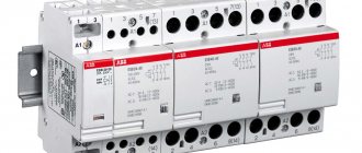
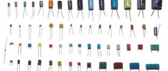
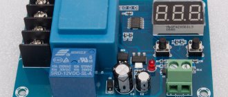
A modular contactor is an electrical electromagnetic device in which control is carried out remotely. By purpose, this is a switching device (used to turn on and off the current in an electrical circuit). The contactor can include from one to four poles of other contacts, and also use alternating and direct current networks (depending on the type: electromagnetic, electropneumatic, pneumatic, lockable). This device is most often used to control powerful electric motors. Because Since it belongs to electromagnetic devices, the force for closing and opening contacts is created by an electromagnet. In this article we will try to consider in detail the principle of operation, purpose and design of the contactor.
How to connect the contact block correctly?
This block is installed on the top of the contactor, where there are special connectors with hooks.
The working circuit has two pairs of closed contacts, as well as two pairs of open connectors.
Normally open contact (NO) – when not working, it is always in the open position (pair 1-2). Therefore, for current to pass through it, it must be closed.
Normal closed contact (NC) - its non-working position is the closure of the connectors (pair 3-4). In this situation, when the contact opens, there will be no current through the magnetic starter.
PM is a structure consisting of two basic fragments:
- top;
- lower
The upper part is a moving contact system, an arc-extinguishing chamber and a moving element of an electric magnet, connected to the connectors by the moving area of the mechanism.
The lower part consists of a winding, a return spring and a second fragment of the magnet body.
The role of the spring is to return the initial position of the upper region of the device, thus, in the absence of contact of the magnetic connector, there is no current in the winding.
Features of a single-phase device
A standard device operating in an alternating current electrical circuit with a frequency of about 50−60 Hz and a voltage of up to 400 V is considered a single-phase contactor. Its design consists of an electromagnetic coil, a spring, an armature and two pairs of normally open contacts.
When voltage appears, a current begins to pass through the coil, generating an electromagnetic field. The force created in it contributes to the attraction of the armature and the closing contacts. Parallel to the movement of the armature, the indicator begins to move, giving a signal at the moment of connecting or opening the contacts.
Once the single-phase voltage is removed, the magnetic field is neutralized. The disconnected contacts return to their initial position due to the action of the spring.
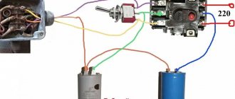
During the installation process, a single-phase MK is installed on a DIN rail in such a way that current passes through it. To connect, use a button and a relay.
Activating the Start button starts the contactor, the closing contacts cause the motor to rotate. Pressing the Stop button breaks the electrical circuit and the engine stops rotating.
As the current in the stator increases, the elements heat up. The presence of a thermal relay allows them to be protected from dangerous overheating. When heated to a critical temperature, the circuit opens and the device turns off.
In this case, you should use a special locking key to prevent erroneous activation. If the arc extinguishing elements are removed during installation, you should avoid turning on the device. This may cause a short circuit in the circuit.
Main function
In many electrical circuits, the role of a device that turns on and off the current is played by a modular contactor. Why it is needed is easy to understand if you understand its design and operating mechanism.
This device, operating using direct or alternating current, has the following components :
- Pole. It consists of a movable spring and a contact that takes its pressure. Responsible for connecting and disconnecting current within an electrical circuit. Eliminates dangerous increases in temperature limits. The silver coating of the pole, made in the form of spraying, ensures its resistance to mechanical damage and extends its service life.
- Electromagnetic coil. It is used to create an electromagnetic field in which moving elements rotate, causing the electrical circuit to close.
- A group of auxiliary contacts. It includes normally open, normally closed and changeover contacts, which act as an indication of the contactor status. The contact system has a time delay.
The parts included in the MK design form an arc extinguishing, contact and electromagnetic system, as well as a block contact system.
The modular contactor mechanism is assembled in such a way that, if necessary, it can be easily supplemented with a contactor attachment, a thermal relay, a time sensor, interlocking equipment and other functional devices used in electrical engineering.
Operating principle
When voltage is applied to the control coil, the armature, under the influence of electromagnetic forces, is attracted to the stationary part of the core, overcoming the force of the spring and selecting an air gap. In this case, the moving contacts of the contactor are pressed against the stationary ones, ensuring the connection of the power electrical circuit.
When the control coil circuit is disconnected, the armature, under the influence of the spring, returns to its original position. In this case, the contacts open. The special design of the arc-extinguishing chambers in which the contacts are placed contributes to the rapid attenuation of the electric arc resulting from a break in the electrical load circuit.
Design and principle of operation
Modular contactors are abbreviated as KM and MK, the devices consist of 2 systems: contact and arc extinguishing, the control element is an electromagnet, and there is also an additional set of contacts.
The operating principle of modular contactors is as follows:
The magnetic field of the network affects the contacts, and they close. When the device is turned on, its coil is saturated with voltage, a magnetic metal armature engages with the core, and then the contacts open or close, it all depends on the initial position of the equipment.
The contact spring ensures fixation of the tension of the contacts, during the joining of which the movable one rolls onto the stationary one. The starter is equipped with additional contacts, with their help the coil is controlled and the reverse motion is activated.
The arc extinguishing system is a limiter that is triggered when the electric arc is abruptly interrupted or voltage surges are observed.
The instructions on how to connect a modular contactor contain extremely useful recommendations that are important to read in advance.
Main types of modular contactors
Actuator. This device provides for the presence of auxiliary contacts, a special relay, and an autostart system, while the automatic system can also be divided into reversible, non-reversible, and with and without switching of windings.
Magnetic switch. The device is a three-pole contactor; it is equipped with two relays that serve for reliable protection.
Intermediate relay - this device has low power; it allows you to increase the number of contacts in circuits in which the current is relatively weak.
Manufacturers label their products differently, each brand has its own designation structure
When choosing a model, pay attention to its purpose; for example, MKs produced by ABB are ideal for automating equipment systems in buildings
Contactors with serial designations MF or MT are used for power or control circuits, and when a device for remote control is required, it is better to choose KME devices.
Features of slot machines of some famous brands
Brands of switchboards for home and business electrical networks produce devices with memorable features. Before purchasing, you should clarify the features of the equipment:
- The Chinese brand "Energy" presents 2 series. 46-73 has no indicators or recesses, suitable for 6 kA current. VA 47-29 – with side recesses, double-sided comb, 6 kA.
- The manufacturer EKF offers devices from the Proxima line with plugs for seals. Budget machines 47-63 come without them.
- The products of the Kursk company KEAZ are easily distinguished by their place of production. Russian VM-63 are suitable for seals, combs, and have contact indication. Chinese VA 47-29 are rated at 4.5 kA, without indicators and holes for the comb.
- Heavy Hungarian GEs are designed for a current of 6 kA and do not have recesses on the sides. Comb area on one side.
- Polish Legrand TX switches for current 6 kA with recesses, but without indicators and combs.
- You can identify the place of production of Shneider Electric by its power. Bulgarian ones are suitable for current from 25 A, everything below is made in China. The Easy 9 series are good inexpensive single-pole models.
- ABB S series products (6 kA) have an indicator, notches, and a one-sided comb. SH switches (4.5 kA) come without combs and indicators, but with recesses.
Using three-switch circuits
Article rating:. The switching mechanism in pass-through switches is located in the center of the contacts.
The device provides comfortable light control and safe movement of people. With such a power supply arrangement, identical devices will not work. The more devices are involved in the implementation of the control system, the more complex the construction scheme becomes.
Useful video Switch from three places - a modern solution for light control Electricity and other resources are rising in price, and the emergence of modern technologies allows for significant savings.
Many novice, non-professional electricians confuse these concepts and try to organize a pass-through circuit on a three-key switch. Take a screwdriver with a phase detector or a multimeter, and look for where the plus is and where the minus is. We are talking about long corridors, stairs, basements.
Let's say one of them will be located near the bed, the second at the exit of the room, and the third near the desktop. The appearance of the duplicating devices is almost the same as that of a single-key device. Three-key pass-through switch Such a switch is not actually a pass-through switch, and cannot be used in a lighting circuit with several switching points. If you need a diagram for connecting a pass-through switch from two places, see it in this article.
During installation, the switches are installed so that when turned off the keys are in the same direction. It contains both an input and an output in the amount of 2. Meanwhile, the cross switch has a completely different circuit and switching mechanism. According to the wiring rules, all wires in such an electrical circuit must be located at a distance of 15 cm from the ceiling. The lighting device is turned on when 2 switches are in the same position.
Similar fastening of the remaining outputs. And the other two are installed on some courtyard buildings, a garage, a shed, upon reaching which you can turn off the lighting. In everyday life, not only step-down transformers are used, but also step-up transformers. The apartment buildings have three floors.
Let's say one of them will be located near the bed, the second at the exit of the room, and the third near the desktop. Connecting a line to a wire with the wrong cross-section. Pass-through switches from 5 places without junction boxes. tokzamer.ru
Purpose of contactors
These devices can be divided according to their main characteristics, although the scope of application is virtually unlimited.
Types of contactors by purpose
- Remote switching devices (switching off, switching). When operating a complex of electrical installations, it becomes necessary to implement a certain power supply algorithm. Manual control: button, switch. The operator gives a signal at the right moment, the AC contactors are activated, switching the power according to a given operating pattern. For example, by pressing one button you can start an entire plant: conveyor, machines, lighting, ventilation system. By connecting many contactors in a certain way, it is possible to automate the power system on the control circuit (in this case, starting commands are given manually). In automatic mode, the command is given using an electronic circuit. The program controls production cycles at the right time, starting and stopping electrical installations. At the same time, any linear contactor can be equipped with a protection function: for example, a limit switch or thermal relay. When certain emergency conditions are created, the power to the coil is cut off and the operating contacts are opened.
- Switching on a powerful electrical installation using a low-current line, or again with a button (switch).
A typical example is an electric motor starter. It would seem, what does a modular contactor have to do with it: what is it for if you can use a button or a switch? Indeed, power can be supplied to the electrical installation directly using the contacts of the button. However, for a reliable connection of a powerful consumer, the contact group and the closing mechanism must be massive, and great force must be applied when turning on. The same force must be used to de-energize. This is not always convenient, especially in an emergency. Therefore, the device with which the operator directly works is compact, it is designed for low current (the consumption of the contactor coil is small), and a small force is required to activate it, especially on the off button. And the linear contactor itself can be quite large, and it operates instantly. Another reason why power separation of control and power lines is used is the high frequency of on and off cycles. For example, electric vehicles. The driver presses the accelerator pedal up to a thousand times per shift. If you equip the lever itself with power contacts, it will be inconvenient to use. Therefore, the pedal only supplies a weak current to the coil, and the line contactor starts the powerful electric motor.
Many of you, being near the driver's cabin, have heard regular loud clicks when pressing the pedal. This is exactly how a line contactor works.
Various drive types
Electromagnetic is the main type and the most common. We discussed the principle of its operation in detail at the beginning of the article.
Unless you can focus on the holding mechanism of the working coil. Most push-button (magnetic) starters do not have a locking button
That is, after the operator removes his finger, the power to the electromagnet should disappear. The design of most starters takes this point into account. There is a contact group on the end plate pusher that closes the solenoid circuit. While the entire electrical installation is working, there is power on the coil. If the voltage drops for a short time (emergency situation, or the disconnect button is pressed), all circuits are broken and the switch is turned on again. This adds safety during operation of the mechanism. After an uncontrolled power restoration, the electrical installation will not start until the operator decides to turn it on. the working day is over, the switch remains closed (the machine is not working, everyone has forgotten about the accident); power on the line is restored, machines, heating elements, etc. begin to work in the deserted workshop.
The use of contactors eliminates such situations.
We've sorted out the electromagnetic thrust. Besides this, there are other ways to set a contact group in motion. Pneumatic devices allow you to close powerful contacts without the use of electromagnetic drives.
The operating principle is the same, only the high pressure pulse acts as a control command. Such devices are widely used on railway locomotives, or other installations where pneumatics are present.
additional information
There is no fundamental difference between a contactor and a magnetic starter, and this has already been mentioned above. Their task is also the same - remotely turning on and off the load. The circuits in which these types of switches are used are also identical. When describing circuits, some specific terms are used. We will dwell on them further for completeness of information.
"Self-pickup." This means that the power button in the push-button station is connected in parallel with a contact that is closed by the action of the coil, the power of which begins immediately when the said button is pressed. Self-retaining, although not mentioned earlier, is present in each of the schemes shown above.
"Reverse". The reverse circuit involves obtaining from two contactors or magnetic starters the switching of the motor windings to change the rotation of its rotor to the opposite. An example of such a scheme is given below.
How to connect a contactor
When connecting a contactor, you immediately need to decide on the mechanism that it will turn on. This could be a motor, pump, fan, heating elements, compressors, etc. The main feature of a contactor that distinguishes it from a machine is the absence of any protection. Therefore, when thinking through the circuits for switching on electrical equipment through a contactor, it is necessary to take into account the current-limiting and heating elements. To limit and shut down equipment in case of short circuits and loads many times higher than the rated load, fuses and circuit breakers are used. Thermal relays are used to prevent long-term slightly exceeding the rated currents of operating equipment.
In order to correctly connect a contactor to a circuit, you need to clearly understand which of the contacts are power and which of them are auxiliary, that is, block contacts. You also need to look at the ratings of the switching coil. The voltage, its type and magnitude, as well as the currents that flow through it for normal operation must be indicated there. During operation, power contacts may burn, so they must be inspected and cleaned regularly.
How to connect a modular contactor
A modular contactor is a type of conventional switching devices of the same type, only they are mainly used for switching switchboards on and off remotely. That is, turning it on, power is supplied to a group of machines, each of which is responsible for its own specific circuit. It is installed on a DIN rail. Can switch both direct and alternating current circuits.
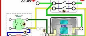
Connecting a contactor via a button
To connect the contactor via a button, you need to study the attached diagram below. It is designed to start a load, in this case a motor, from a contactor whose coil is designed for 220 Volts alternating voltage. Depending on the voltage, it is worth considering its power supply. Therefore, when purchasing and selecting a contactor, it is worth taking this nuance into account. Since if the electromagnet is designed for constant voltage, then such a source will be needed.
When you press the start button, the contactor electromagnet coil will receive power and it will turn on. The power contacts will close, thereby supplying voltage to the asynchronous motor. The block contact of contactor K1, which is connected in parallel to the stop button, will also close. It is called by electricians a self-retaining contact, since it is this that supplies power to the switching coil after the start button is released. When you press the stop button, the power from the electromagnet is turned off, the power elements of the contactor break the circuit and the engine turns off.
Connecting a contactor with a thermal relay
The thermal relay is designed to prevent prolonged minor current overloads during operation of electrical equipment, because overheating negatively affects the condition of the insulation. Frequent excesses of temperature and current will lead to its destruction, and therefore to a short circuit and failure of an expensive actuator.
When the current in the stator circuit of the electric motor increases, the elements of the thermal relay KK will heat up. When the set temperature, which can be adjusted, is reached, the thermal relay will operate and its contacts will break the circuit of the electromagnet coil of the KM contactor.
For safety reasons, you must remember that work in the contactor circuit must be carried out when it is completely de-energized. In this case, the power supply must be locked with a key or prohibiting sign from unauthorized or erroneous activation. And also you cannot turn on this device with the arc chutes removed, this will lead to a short circuit.
Mistakes made when installing MK
The most common mistakes made when connecting electrical equipment through modular contactors are the result of inattention or ignorance of operating rules.
Error 1. Refusal to install automatic protective equipment in the power circuit.
This is fraught with disruptions to the operation of equipment, which is unprotected from emergency modes and network changes. The result may be its failure or electric shock to operating personnel (in the event of a current leakage to the housing).
Error 2. The absence of “foolproof protection” on the reversing circuit, that is, additional contacts that prevent the simultaneous activation of two launch modes.
Such a defect can cause a short circuit and serious damage.
In conclusion, it should be noted that the modular contactor is a universal switching device, perfect for use in production and at home. The main condition is compliance with operating procedures and safety rules.
Purpose of a modular contactor
The main purpose of the contactor is to regularly or frequently turn off and turn on electric current circuits. The ability to perform such manipulations remotely allows the use of such devices for utility purposes (lanterns, elevators), ventilation systems, heating and water supply systems. Also, equipment of this kind is used in electric transport: electric trains, trams, trolleybuses.
Despite such a wide scope of application, such devices have a number of types that are used for strictly regulated purposes. For example, an electromagnetic starter is a type of contactor used only for starting AC electric motors. Also, a thermal protective relay - another type of contactor - is used to protect motors from overheating.
Where and why is it used?
Most often, a modular contactor is used to control and switch a heating pump and other various devices (for example, in ventilation systems). They have become popular and in demand when assembling panels in apartments and various automation systems. For example, control of light, well pump, automatic reserve switching circuit, and so on. Why? Because the contactor fits perfectly with other modular devices, without disturbing the ergonomics of the switchboard. You can verify this by looking at the visual example in the photo:
It is worth remembering that the mains voltage should be no more than 380 Volts at a frequency of 50 Hz. But despite this, the contactor can operate at high powers. There are several other advantages of this device. Such as the almost complete absence of noise and vibration, which has a rather positive effect when used not only in a home panel, but also in public places (hospital, apartment, schools, institutes, etc.), since other switching devices are too susceptible to strong vibration.
By the way, size matters. After all, the small size of the modular contactor allows it to be installed on a DIN rail. The design includes arc-extinguishing chambers to extinguish the arc that occurs when the current load changes. In addition, there are single-phase and two-phase contactors, which allows you to connect to any network.
You can learn more about modular contactors by watching this video:
What is the difference between a contactor and a starter?
Not only specialists with higher specialized education, but also equipment adjusters with impressive practical experience rarely understand how, in principle, an AC contactor differs from an electromagnetic starter. You can figure this out on your own.
What do a starter and a contactor have in common? They are both used for switching power circuits; with their help, AC electric motors are started, and for rheostatic starting, resistance stages are introduced/disconnected.
In addition to power contacts, the starter and contactor have at least 1 pair of control contacts - normally closed or normally open. This is to make these devices similar. But there are also serious differences.
Electromagnetic starters in the price lists of many trading companies are listed under the name “small-sized AC contactors.” Perhaps this is the main difference between these devices - the starter is compact? In fact, with an identical rated current load, the overall dimensions of the starter and contactor differ at first glance.
The 3-pole 100-amp contactor has quite impressive dimensions, and the dimensions of the 100-amp starter are an order of magnitude smaller. At the same time, contactors for low currents (about 10 amperes) are not even produced. Circuits with low current are switched only with the help of starters, and their dimensions are minimal. So one of the important differences between starters and contactors is indeed their dimensions.
But they also differ in their design features. Contactors are not provided with their own housing, so they must be installed in specially equipped and almost hermetically sealed rooms, where exposure to moisture from the atmosphere (or any other sources) and access by unauthorized people is completely excluded. The contactor includes special pairs of high-power power contacts equipped with chambers to extinguish the electric arc.
The plastic housing of the starters protects their power contacts, but they do not have special volumetric chambers designed to extinguish the electric arc. Therefore, it is not recommended to install starters in electrical circuits with high power and frequent switching, since their contacts are practically not protected in any way from an electric arc, which occurs in many cases.
But if the starter is additionally equipped with a sealed metal casing, it becomes capable of providing reliable equipment protection to a much greater extent. And you can even install it outdoors, in the open air, but under no circumstances should you do this with a contactor.
Purpose is another difference between a starter and an AC contactor. The starters are designed primarily for starting 3-phase asynchronous AC motors. Although they are used to control the power supply to powerful lamps of various designs, electromagnetic coils, heaters and other electrical appliances.
Each of the starters has 3 pairs of power contacts, and the control contacts in it serve to keep it in the on state, as well as for installing complex control circuits in which, for example, reverse starting is necessary.
The purpose of the contactor is to switch almost any alternating current circuit, as a result of which a different number of pairs of power contacts are installed in them - usually from 2 to 4 poles.
Thus, AC switching electromagnetic power devices into starters and contactors are divided according to the 3 differences listed above.
Prepared
from 185A to 2500A
Contactors DILM up to 1000 A (AC-3) and DILH up to 2500 A (AC-1)
Eaton/Moeller produces contactors up to 2200 A. All DIL M contactors from 185 A to 2200 have an electronic control coil drive. You can choose between two options: standard and comfortable.
Advantages of the standard version of contactors from 185A to 500A:
- The heat transfer in the contactor chamber is significantly reduced;
- Long service life due to optimized contact force;
- Integrated suppressor;
- Additional contacts: 2 normally open, 2 normally closed;
- Advantageous offer when purchasing the standard version.
Advantages of the comfortable version of contactors from 185A to 2500A:
- Expanded possibilities for using contactors in the comfort version;
- Significantly increased reliability during voltage fluctuations due to an expanded voltage range;
- Control directly from PLC.
DIL M contactors from 580 A are vacuum and have the following advantages compared to air ones:
- The contact chamber does not require any maintenance during the entire service life of the contactor;
- The service life is significantly higher than that of air contactors;
- Possibility of installing high-density vacuum contactors.
| Starting and protection of electric motors 2010 | 4.46 MB |
Design of electrical classic contactors
Classic electrical contactors - also known as magnetic starters - usually have groups of contacts - main and auxiliary.
Contact groups (most often) are in a normally open state. Only if the supply voltage is supplied to the induction coil of the device, the contact groups of the device change their state.
The top three terminals of the main group are used to connect the input three-phase alternating current, usually with a voltage of at least 380 volts. This contact group is equipped with reinforced screw terminals marked “L1”, “L2”, “L3”.
Purpose of the terminals: 1 - line voltage supply; 2, 11 — output under load; 3, 5 — coil power supply; 4, 6 - auxiliary; 7 - sensitivity; 8, 9 — manual shutdown and reset buttons; 10 - auxiliary group
The second main group of terminals, assigned to power the load (electric motor or other), is located at the bottom of the device structure and also has screw terminals marked “T1”, “T2”, “T3”.
Each device is traditionally marked with an alphanumeric combination of symbols. The marking is located on the body of the device and carries basic information about the device. For example:
A – 26 – 30 – 10
Here the symbol “A” denotes the series of the device. Next, the number “26” marks the rated current (26A) for the load in the form of an asynchronous electric motor.
The number “30” indicates the number of normally open and normally closed power contacts (3 and 0, respectively). The number “10” indicates the number of auxiliary “NO” and “NC” contacts (1 and 0).
Purpose of auxiliary switching
Auxiliary contacts are often used as part of a relay logic circuit or used as part of some other part of a load control circuit. Typical switching voltage here is 220V AC.
Connection diagram (classic): 1 - magnetic starter; 2 - current protective relay; 3 - electric motor; 4 — “STOP” button; 5 — “START” button; 6 — alarm reset button
Auxiliary contact groups may have different configurations, depending on the device model and manufacturer. The contact state can be either normally closed or normally open. Usually there is a combination of conditions.
The auxiliary interface terminal set is usually designed for a current rating significantly lower than that of the main contacts.
However, the auxiliary group mechanism operates in conjunction with the main switching mechanism of the electrical contactor.
Typically, auxiliary terminals are marked with a digital code. For example, “13” and “14”, “82” and “83”, etc. To some extent, the power terminals of the inductive coil of the electromagnetic system of the device also belong to this category.
The coil power terminals are traditionally marked “A1” and “A2”. The control voltage of the electromagnetic mechanism is supplied to these terminals, usually according to the classical scheme (see above).
Connection diagrams for a magnetic starter with a 220 V coil
Before we move on to the diagrams, let’s figure out what and how these devices can be connected. Most often, two buttons are required - “start” and “stop”. They can be made in separate housings, or they can be a single housing. This is the so-called push-button post.
Buttons can be in the same housing or in different ones
Everything is clear with individual buttons - they have two contacts. One receives power, the other leaves it. There are two groups of contacts in the post - two for each button: two for start, two for stop, each group on its own side. There is also usually a ground terminal. Nothing complicated either.
Connecting a starter with a 220 V coil to the network
Actually, there are many options for connecting contactors; we will describe a few. The diagram for connecting a magnetic starter to a single-phase network is simpler, so let's start with it - it will be easier to understand further.
Power, in this case 220 V, is supplied to the coil terminals, which are designated A1 and A2. Both of these contacts are located at the top of the case (see photo).
This is where you can supply power to the coil.
If you connect a cord with a plug to these contacts (as in the photo), the device will be in operation after the plug is inserted into the socket. In this case, any voltage can be applied to the power contacts L1, L2, L3, and it can be removed when the starter is triggered from contacts T1, T2 and T3, respectively. For example, a constant voltage from a battery can be supplied to the inputs L1 and L2, which will power some device that will need to be connected to the outputs T1 and T2.
Connecting a contactor with a 220 V coil
When connecting single-phase power to the coil, it does not matter which output is supplied with zero and which with phase. You can switch the wires
Even most often, the phase is supplied to A2, since for convenience this contact is located on the bottom side of the housing. And in some cases it is more convenient to use it and connect the “zero” to A1.
But, as you understand, this scheme for connecting a magnetic starter is not particularly convenient - you can also supply conductors directly from the power source by building in a regular switch. But there are much more interesting options. For example, you can supply power to the coil through a time relay or a light sensor, and connect the street lighting power line to the contacts. In this case, the phase is connected to contact L1, and zero can be taken by connecting to the corresponding coil output connector (in the photo above it is A2).
Diagram with start and stop buttons
Magnetic starters are most often installed to turn on an electric motor. It is more convenient to work in this mode if there are “start” and “stop” buttons. They are connected in series to the phase supply circuit to the output of the magnetic coil. In this case, the diagram looks like the figure below
note that
Switching diagram of a magnetic starter with buttons
But with this method of switching on, the starter will operate only as long as the “start” button is held down, and this is not what is required for long-term operation of the engine. Therefore, a so-called self-catching circuit is added to the circuit. It is implemented using auxiliary contacts on the starter NO 13 and NO 14, which are connected in parallel with the start button.
Connection diagram for a magnetic starter with a 220 V coil and a self-retaining circuit
In this case, after the START button returns to its original state, power continues to flow through these closed contacts, since the magnet has already been attracted. And power is supplied until the circuit is broken by pressing the “stop” key or by triggering a thermal relay, if there is one in the circuit.
Power for the motor or any other load (phase from 220 V) is supplied to any of the contacts marked with the letter L, and is removed from the contact marked T located underneath it.
It is shown in detail in what order it is better to connect the wires in the following video. The whole difference is that not two separate buttons are used, but a push-button post or push-button station. Instead of a voltmeter, you can connect a motor, pump, lighting, or any device that operates on a 220 V network.
Classification of contactors
By type of applied voltage:
- Constant voltage.
- Variable voltage.
By the type of current in the secondary circuit:
- Direct current.
- Alternating current.
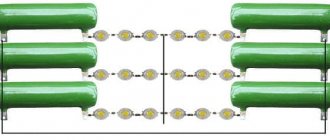
By the number of switched poles:
- One pole.
- Two poles, etc.
Based on the presence of an arc extinguishing device:
- There is a suppression device.
- Absent.
When a device is triggered, impulses appear in the network that have a harmful effect on other systems receiving power from the same network, and radio interference also occurs. Nearby devices may not operate properly under these conditions. To eliminate this effect, some types of contactors are equipped with a protection system against self-generated interference.
The principle of operation of the contactor: an electrical current is supplied to the coil, which creates an electromagnetic field that magnetizes the core.
When large loads of an inductive nature are turned on using a contactor, an electric arc occurs between its contacts, leading to burning of the active substance on the switching plates. Typically, silver is used to improve performance at the junction. It has a fairly high price and in case of burnout leads to additional costs for restoration or replacement.
In order to eliminate this drawback, contactors are equipped with additional devices that can extinguish the electric arc that occurs during connection. Contactors are capable of connecting loads with very high voltage and current.
3 pole contactors
XStart Innovations
The new series of DIL M contactors is designed for starting motors up to 170A. The new series of contactors has smaller dimensions, reliable connection of mounted wires in two ways “with a screw” and spring clamps.
Design |
- Only 4 main types instead of 7
- Only 3 sizes up to 170 A width
- Additional contacts integrated into the contactor
Installation |
- The control contacts are located on the front plane of the contactor
- AC and DC contactors are the same size
Exploitation |
- Integrated suppressor in contactors with constant current control
- Reduced energy consumption of contactors
- AC suppressor is easily installed in a special front socket
- Coils with extended control range for DC contactors from 18A
Design
Eaton/Moeller has reduced the number of basic types from 7 to 4 with only three contactor width sizes (45 mm to 32 A, 55 mm to 72 A and 90 mm to 170 A). The first two main types of contactors are the best compromise between minimum size, performance and additional control benefits.
Contactors are devices for global markets. They are UL and CSA licensed.
Installation
Double clamps are installed on DILM contactors up to 170 A. Wires of different sections are securely secured in double clamps. Double clamps can be used even if the contactor is subject to strong vibrations. Installation is easy and reduces the risk of possible problems.
Eaton/Moeller also offers proven, high quality spring terminal contactors. For contactors up to 15.5A, spring clamps are installed on power and control contacts. For contactors above 15.5A, spring terminals are installed only on the control contacts.
Numerous tests have proven that contactors and motor protection circuit breakers with spring terminals have the same performance as devices with screw terminals. Even if the contactor with spring terminals is subject to strong vibrations, spring terminals can be used. However, they have the main advantage - speed of installation.
AC and DC contactors are the same size. Thus, the dimensions of the device do not depend on the voltage value.
Exploitation
All DC contactors also have an integrated suppressor. Extended operating range control voltages for DC contactors exceed the regulated operating range established by IEC standards and provide optimal protection against extreme high or low voltage conditions.
| Starting and protection of electric motors 2010 | 4.46 MB |
Where and why it is used
Most often, a modular contactor is used to control and switch a heating pump and other various devices (for example, in ventilation systems). They have become popular and in demand when assembling panels in apartments and various automation systems. For example, control of light, well pump, automatic reserve switching circuit, and so on. Why? Because the contactor fits perfectly with other modular devices, without disturbing the ergonomics of the switchboard. You can verify this by looking at the visual example in the photo:
It is worth remembering that the mains voltage should be no more than 380 Volts at a frequency of 50 Hz. But despite this, the contactor can operate at high powers. There are several other advantages of this device. Such as the almost complete absence of noise and vibration, which has a rather positive effect when used not only in a home panel, but also in public places (hospital, apartment, schools, institutes, etc.), since other switching devices are too susceptible to strong vibration.
By the way, size matters. After all, the small size of the modular contactor allows it to be installed on a DIN rail. The design includes arc-extinguishing chambers to extinguish the arc that occurs when the current load changes. In addition, there are single-phase and three-phase contactors, which allows you to connect to any network.
You can learn more about modular contactors by watching this video:
Types of contactors by installation method
Unframed or specialized devices (for example, a line contactor in a trolleybus) have no design restrictions and are developed based on functionality and safety considerations. There are also special designs created for certain electrical installations. Such switches are not used in domestic conditions, since they require separate locations.
For ease of use in standard electrical panels, standard modular designs are used for mounting on DIN rails.
They fit perfectly into the overall energy supply system of a home or office, if their use is provided for by the project.
What is a contactor
Contactors are special devices for turning on and off an electrical circuit of various power and voltage. In this case, the action is performed automatically or via a remote control panel. An electromagnetic drive is used for operation, and the device itself consists of:
contacts: main and additional;
Such a device can replace both a relay and a regular switch. At the same time, the device is designed for long-term operation and is assembled from durable, wear-resistant materials and elements.
Why do you need a contactor?
Just like the subtypes, the original contactor is needed to control the electrical circuit. But it has several operating features:
the ability to fully automate the switching on and off of the circuit;
high speed of operation, allowing the circuit to be closed and opened up to several thousand times per hour.
Thanks to these features, contactors are used in areas where electrical circuits need to be activated regularly and frequently. Doing this manually is not only inconvenient, but even ineffective. So it is better to entrust the work to an automated system.
Where are contactors used?
What are contactors used for? The areas of application of these devices are varied:
utilities: management of lighting, elevators, ventilation and heat and water supply systems;
in industry and construction, contactors are found in almost all electrical devices;
for electric transport: in trams and trolleybuses, these devices are responsible for the operation of the traction motor;
in domestic conditions, with the help of contactors, they automate the operation of intra-house electrical networks.
Depending on the functions, there are also highly specialized contactors designed to work, for example, only with motors or construction electrical equipment. Before you buy a device of this type, you need to decide exactly where and under what conditions it will work.
What types of contactors are there?
There are many models designed to work in different conditions, from varying weather conditions to current ratings. But the general classification includes only two types:
Direct current. Needed to conduct current of the appropriate type. These are the devices that are installed in most electric traction engines.
Alternating current. These are designed to conduct, respectively, alternating currents directly to the desired equipment or to the power supply.
Contactors are presented in a wide range of models, and in order to choose the right device you need to know the parameters of the electrical network.
Technical characteristics of GE CL contactors:
- Control circuit: alternating current up to 690 V; DC up to 440 V.
- Terminal numbering in accordance with EN 50005 and EN 50012.
- Fixation with clamps on 35 mm DIN rail EN 50022-35 or with screws.
- The screws are protected against accidental contact in accordance with VDE 0106 T.100, VBG4.
- Three coil terminals.
Among the accessories intended for use with CL contactors, we note:
Coils for different voltages. The presence of a wide range of coils for General Electric CL contactors allows distributors and switchboard manufacturers to keep in stock contactors assembled with coils for the most popular voltages, as well as coils for all other voltages. The coils are easy to install and dismantle if necessary.
Auxiliary contacts for front and side installation. Allow contactors to be used in complex circuits where standard contacts are not enough.
Pneumatic relays. Designed to turn on control circuits with a delay relative to the contactor response time. They are a mechanical device and do not consume electricity. Allows you to accurately set the delay time: there are relays for the range of 0.1–30 seconds and from 1 to 60 seconds. Relays for switching on and switching off are supplied. In addition, the range includes pneumatic relays for contactors with screw mounting and ring terminals.
Electronic timer module. Designed to turn on control circuits with a delay relative to the contactor response time. It is installed on the coil contacts, which allows it to be used in conjunction with auxiliary contact blocks. Both modules that operate on and off are supplied. There are timers in the ranges of 0.1–2 seconds and 1.5–45 seconds.
Transient Voltage Suppressor - is installed on the coil contacts and protects it from the effects of overvoltage. Can be used simultaneously with auxiliary contact blocks.
Interface module - installed on the coil contacts, which allows it to be used in conjunction with additional contact blocks. Designed to expand the functions of the contactor.
Contact sets - designed to replace broken or burnt contacts.
Labels and sets of plates with labels - designed for marking contacts.
What is a modular contactor
A modular contactor is a special electrical equipment of the electromagnetic type that operates and controls remotely. If we talk about its purpose, the device is usually used in electrical networks to turn on and off the current supply. One contactor can have up to four poles of other contacts and be installed in the network as alternating current or direct current (depending on its type).
Two-pole MK
Note! It is most widespread in the control of powerful electric motors. Obviously, if the device is electromagnetic, then its closing capacity is based on the electromagnet
Device in the apartment panel
As already mentioned, a contactor is better suited for closing than a switch, since it closes and opens the circuit up to several thousand times per minute, does this remotely and completely automatically.
Preparing for connection
The connection diagram of the contactor is directly dependent on the equipment with which it will operate. In addition to engines, all kinds of fans and pumps, compressors, heating elements and other devices act in this capacity. It is necessary to take into account the specifics of the contactor apparatus, which, in comparison with automatic machines, is not equipped with any protection. Therefore, when developing networks used to connect equipment, factors affecting current performance and the degree of heating must be taken into account.
Additionally, it is necessary to consider protective measures in case of short circuits and loads many times greater than the contactor rating. This problem can be solved by installing fuses. This category includes a circuit breaker, as well as thermal relays that protect equipment from prolonged excess current ratings and overheating.
Before connecting, you need to find out which contacts are the main ones and which of them perform an auxiliary function. Each switching coil has its own rated currents and voltages indicated in the marking.
Certain features exist when installing and connecting a modular device, which is a type of ordinary switching device. Such a contactor in the diagram is used to switch on and off at a distance equipment installed in distribution panels, including ABB. It follows that when a modular contactor is put into operation, power is supplied to a certain group of machines connected to certain circuits. Devices of this type operate successfully with all types of currents.