Next, the circuit operates according to an algorithm depending on the direction of rotation of the motor. Electric motor connection diagram We will talk about connecting an asynchronous electric motor when connecting the windings with a star or delta in the V network. We hope that our instructions for connecting a magnetic starter with diagrams and detailed video examples were clear and useful for you! If the magnetic action is not observed when the START button is released, the contacts are not fixed, but fall off, therefore, the whole point is in their incorrect connection. A coil with calculated volts is connected to the terminals between ground and phase. Connection diagrams for a magnetic starter (contactor) - Operating principle The general parameters of the coil are fully consistent with the technical characteristics of the starting devices. The faster the opening occurs, the smaller the arc and the better condition the contacts themselves will be.
Each pair has both mobile and fixed contacts connected to the terminals located on the body via metal plates.
The diagram shows that starter coil 5 is powered from phases L1 and L2 at voltage V.
The location of additional contacts determines the difference between a contactor and a magnetic starter. The device will work reliably if its installation location is on a straight, flat, and vertical surface.
Connection Instructions The easiest connection option is via a button. Therefore, after the contactor has tripped, it can be released.
Connection and connection of the starter (contactor)
What is a modular contactor and what is it for?
According to its functional purpose, the modular contactor KM belongs to the switching equipment for remote control of powerful loads operating at direct or alternating current. They break current circuits in several places at once, and this differs from electromagnetic relays, which break the circuit at only one point.
Quite often, modular contactors work in conjunction with auxiliary devices - set-top boxes, thermal relays, blocking devices and other modular devices. As a result of such combinations, equipment is obtained that has special properties and is capable of performing specified functions. So, when installing a delay module, you get a contactor with a delay function, and a thermal overload relay transfers the contactor to the category of a magnetic starter. With the help of auxiliary elements, the capabilities of the main devices are significantly expanded, their performance characteristics are improved, and installation is simplified.
At their core, contactor devices are considered modified versions of a starter, which additionally contains a thermal relay and a contact group for starting the electric motor. Low voltage electromagnetic starters, reversible and non-reversible. The first option includes two identical contactors, with the same rated current. It has a mechanical or electrical interlock that prevents the main contacts from closing at the same time.
The protective functions in these devices are performed by electrothermal current relays and other similar devices. Low power electrical contactor, used as an intermediate relay. It is designed for low-current circuits and has a large number of switchings. Using this device, it is possible to connect many additional sections and control their on/off.
Specifications
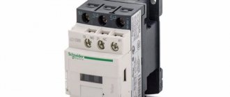
Each individual modular contactor has its own operating parameters, so we suggest considering the most popular models from Schneider Electric, IEK, ABB and others.
Photos - dimensions and characteristics of models KM, MT and MF
Schneider Electric iCT16A 1NO 1 NC:
| Current strength, A | 6–16 |
| frequency Hz | 50/60 |
| Performance | 100 cycles per shift |
| Switched device power, W | 2,1 |
| Polarity | 2 poles |
| Approximate wear resistance | 200000(AC and DC) |
| Protection | IP20 |
| Climatic performance | UHL, 40–70 °C |
Modular electromagnetic contactor IEK KM20-20 2P 20A 230V:
| Current, A | 20 |
| frequency Hz | 50/60 |
| Job | 150 cycles per shift |
| Power, W | 2 |
| Polarity | 2 poles |
| Wear resistance | 300000 |
| Protection | IP20 |
| Temperatures, °C | UHL, 40–70 °C |
The advantage of this particular model is the ability to quickly switch modes, up to 30 seconds, regardless of the network voltage. In addition, the contactor is equipped with an optical warning and control system, which increases operating comfort. Small dimensions allow the switch to be used in a standard household panel.
ABB, ESB series (there are also GHE and ES):
| Energy, A/V/Hz | 20–63/230/50 |
| Frame | Sealed, protected from penetration of solid particles |
| Job | From 150 cycles |
| Power, W | From 2.2 |
| Number of poles | 2 |
| Durability | From 200000 |
| Protection | IP40 |
| Temperatures, °C | UHL, 40–70 °C |
These are special contactors (ESB-20-20, ESB-24, ESB-40-40, ESB-63 series), which are worth noting due to their high level of protection. In addition to the tightness of the case, the advantage compared to many other models is the safety of operation (for example, from touching or fire). This device is electromagnetically controlled, so switching is almost silent.
The ACTP 230V surge arrester for CT is a special contactor, the use of which is mainly beneficial in production. It has high switching power, wear resistance and other parameters that are necessary for industrial use. The device can be connected to both a two-phase network and a three-phase network.
| Network, A/V/Hz | 25/230/60 |
| Consumption, VA | 3 |
| Installation principle | Using cable and 4 mm2 clamps per rail |
| Durability | 3 million cycles |
| Protection | IP40 |
| Climate | UHL, -40–70 °C |
| Frame | Explosion-proof, sealed |
Benedict R20-20 230:
| Rated current, A | 20 |
| Switching | 300 cycles per hour |
| Wear resistance | 1 x 10⁶ |
| Voltage, | 230 |
| power, kWt | 4,6 |
| Temperature range | -40 to +60°C |
Dekraft MK-103-16 (KM-103-16 EKF):
| Current, power, voltage, A/W/V | 16/4/230 |
| Mechanical wear resistance | 30 000 |
| Operating temperature range | -5–40°C |
| Protection | IP 20 |
Moeller Z-SCH230/25-40:
| Current, A | 25 |
| Number of poles | 4, also 4 open mods. |
| power, kWt | 12,5 |
| Wear resistance | 3 million |
| Net | Three-phase |
TDM KM63/4-63 4NO 63A 230V:
| Frame | Plastic fire resistant |
| Current, A | 63 |
| Voltage, V | 230 |
| Polarity | 4 |
| Degree of protection | IP20 |
Video: connecting modular contactors
Classification of contactor devices
There are different types of contactors, differing from each other in various respects. Among them, the following parameters can be distinguished.
First of all, they are classified according to their purpose. This includes the following types and categories:
- Devices for remote switching. Most of them operate under manual operator control using buttons or switches. At the right time, a signal is given and the device is activated. In another method, several contactors are connected into a common automated power system that uses electronic circuitry to issue commands. In case of an emergency, a protection system is provided that opens the contacts.
- Switching on powerful electrical equipment using low-current lines. The question arises, why is a contactor needed in such cases? Wouldn't it be better to use a traditional button? This, of course, can be done, but then you will need very massive and bulky equipment, and the switching process itself will require significant effort. The same goes for turning it off. Therefore, compact low-current devices are used for these purposes, allowing for high-frequency on-off cycles. Thus, a weak current is supplied to the coil, and only then the powerful electric motor is started.
CS-CS.Net: Laboratory of the Electroshaman
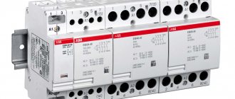
ABB ESB series contactor (DIN rail mounted)
Recently, I accidentally came across a dead ABB ESB 24-22 (current up to 24 amperes per contact, 2 NO, 2 NC contacts), and since I work with these contactors, and these are my favorite contactors for household panels, then, of course, I decided to imagine myself as a pathologist and dissect this wonderful product. Well, at the same time, tell everyone who doesn’t already know what a contactor is and why it is used. Moreover, in the entry about relays (Automation: Relays (Intermediate ABB CR-P; Self-locking relays)) I promised to do this.
Slightly reworked the post in 2022. Added sections on contactors, added photos of additional contacts.
What are contactors and why are they needed?
In fact, everything is simple: A contactor is a powerful relay. With powerful contacts, from which its name comes. Well, if we talk about names, then this device can be called in different ways: it is a power relay, a powerful relay, a contactor or a starter. The last word comes from the time when these devices were used to turn on powerful engines and put them to work. Well, to be completely fair, a starter is often called a ready-made box with “Start” and “Stop” buttons, a contactor and a motor protection thermal relay inside, designed to start this very engine. Now these concepts are mixed, and I have heard many times from different people both versions of the name: contactor and starter. The name “contactor” stuck with me, and I’ve been calling them that ever since.
What is it for? And everything is simple - switch something powerful. For example, motors, lighting, heaters and other power circuits. The contacts of contactors are precisely designed to operate at high currents, at levels that conventional relays cannot handle. If conventional relays have a range of operating currents of approximately 1-15-30 amperes, then contactors can easily operate with currents measured in tens or even hundreds of amperes. Well, for example, contactors can easily be found for currents of 150, 250 amperes.
In addition, the contactor is no different from a regular relay (I mentioned them in the post about self-locking relays and in the post about the ABB series of intermediate relays). It also has power inputs for its windings (coils) A1 and A2. If you apply rated voltage to them, then its contacts will change their state. That's the whole system!
Well, let me also note that most often modular contactors on a DIN rail have 4 contacts per closure, since most often they actually control three-phase loads. And since to turn off the power to a three-phase load, it is enough to at least disconnect all three phases of the power supply, the fourth “free” contact for closure can easily be used to self-block the contactor. Well, in fact, contactors of common series have a bunch of bells and whistles. These are additional contacts that are hung on the contactor in all directions, this is a blocking and a bunch of other things.
Safety rules when working with contactors: normally open contacts.
I wrote this insert in 2022. So, since 2011, when I wrote this post about contactors, I have heard a lot of ideas from various Kulibin creatures who periodically write to me on blog pages or in soaps about an innovative idea that came to their mind: so that the contactor does not work always and all the time, you need to take it with normally closed contacts.
Such decisions are PROHIBITED by safety rules (and I once got so angry that I wrote a post about how you will die). In automation and especially in power circuits, there is one main rule: if the control circuits are broken or de-energized, then all power circuits must turn OFF.
These rules are written, as usual, in a lot of blood. And people were wound up on the machines because of “yes, the electricity turned off for a short time, and I climbed, I thought the belt from the engine had broken,” and the elevators were moving (below I will insert a video from the famous channel “Everyday Life of Liftovik”), and cranes, and whatever .
Therefore, if you hear somewhere about normally closed contacts and “well, when I want to turn off the lights in the entire apartment, then I will turn on the contactor, and it will only work for that time” - hit such people in the scoreboard, without sparing them ! Well, in suppliers’ warehouses you will most often find contactors with normally open contacts, and normally closed contacts will be made to order.
ATS (input switching) on contactors. What should and should NOT be done?
And continuing the theme of motherfuckers with nails in their heads (and there’s no other way to call them), we gradually come to another strict safety rule. Here it is not always fraught with the deaths of specific people. More often, heh, fires occur in switchboards or good and evil short circuits that shut down substations.
I’m talking about ATS ( automatic switchboard ) on contactors, the main advantage of which is low cost (you can get 250A contactors from IEK for 10 thousand a piece ) and speed ( switching inputs happens quickly).
The essence of this ATS is that a contactor is placed on each of the two inputs, which is powered from the same input through interlocking circuits. Here is a photo from a panel with IPM™ ATS on contactors, which I made in Popovka (read it, the concepts of such an ATS are described there).
ABB AF38 contactors for automatic transfer switches: 4 poles, with mechanical and electrical interlocking
There are two contactors for two inputs. Is it clear to everyone that these two contactors should NEVER be turned on, because the bang will be due to the fact that the two inputs will be connected to each other? Is it clear that if the inputs are three-phase and you are lucky enough that at the moment of switching on they are in antiphase, then it will sound not 400V, but 400 + 400 = 800 V? And it’s not even this that’s scary (well, it’ll knock out the circuit breakers and to hell with it), but the fact that you can supply power where it’s not needed. For example, electricians have disconnected a section of your rural network and are digging into the lines in the village. And then your AVR suddenly gave 230V into the line from the generator... and death!
To prevent this from happening, two types of blocking are used, which - oh, attention! - are available only in the industrial lines of contactors, which are shown in the photo above:
- Mechanical interlock . This is the most IMPORTANT lock! It is an additional accessory that can be purchased for contactors (in my photo it is located between the contactors and is not visible). This is a lever or insert that is installed between two adjacent contactors and physically prevents the second contactor from operating (pulling contacts) if the first one is turned on.
- Electrical locking . It is made either on additional contacts (in my photo these are the things standing on the sides of the contactor assembly) or sold as a ready-made accessory. Its operating principle is similar to a mechanical one, only here, through additional contacts, the coil circuit of the second contactor is broken if the first one is turned on.
Therefore, let's choose the hard option: it is IMPOSSIBLE to make ATS on modular ones (automatic machine format, plastron modules), because such contactors do not have mechanical interlocking ! Electrical can be done using additional contacts, but more important is mechanical!
And that’s not all they try to do with contactors! The second group of walking chromosomes with nails in their heads are those who are trying to make an automatic transfer switch on one contactor with switching contacts. Further in the text of the post you will see that I broke the ABB ESB24-22 contactor, with switching contacts that were very burnt. Most likely, the reason for this is that they tried to make just such an ATS on such a contactor.
And this has also run through comments on the blog over the years. Geniuses of thought come up with such a solution and even try to produce such horror in a production line at a factory. Here is a photo of ShchAP. Enlarge it and look at the diagram:
An example of an ATS shield on a contactor with switching contacts (this cannot be done O_o)
This is PROHIBITED for two reasons:
- Reason one . Some of the contacts of such a contactor will always be normally closed, which contradicts the safety rules that we talked about before: if any of the control circuits are de-energized, then all power circuits must be OFF!
- Reason two . No manufacturer, including ABB and other major brands, ever guarantees that first one group of contacts will open (the first input will turn off), and then the second will close (the second input will turn on). With such contactors, all contact groups switch simultaneously, and therefore there is a high probability that this contactor inside will cause a short-term short circuit between two inputs.
NEVER DO THIS! Use only contactors from industrial lines that have mechanical and electrical interlocks!
ABB ESB series contactors.
Well, now let's take a closer look at the ABB ESB . This series is the most common and is notable for the fact that it was designed specifically for “home” automation. That is, it is not stuffed into industrial cabinets from floor to ceiling, but into ordinary panels on a regular DIN rail, having the same dimensions as conventional machines. And therefore, you can absolutely safely shove it into any shield, which is what I usually do. Additionally, the catalog stated that this series has a rectifier inside that powers the coil with direct current, which is why it will not buzz. Well, that is, this contactor is positioned as quiet, for apartments. True, if you look through the catalog (“Don’t read Soviet newspapers at lunch” ©), you can see that this DC power feature is used in almost all contactors from ABB. And some of them even contain a switching power supply inside, due to which the range of supply voltages of this contactor is expanded.
These contactors are designated very simply: ABB ESB-xx-yz. ESB is a series. XX is the current of each contact in amperes. There are 20, 24, 40 and 63A. Y is the number of contacts for closing, Z is the number of contacts for opening. That is, our ESB 24-22 means a current of 24A, and two contacts for closing and opening. And ESB 40-40 will mean 4 contacts for closure with a current of 40A each. Contactors with a current of 20A occupy only 1 DIN module, with a current of 24A - two modules, and with a current of 40 and 63A - only three modules on a DIN rail. Well, it should be noted that a DC coil is available only with two-module contactors (from 24 amperes), because in a single-module design there is nowhere to push it.
Well, now - the preparation. Let's take a look inside. Let's remove the top cover. Underneath there is indeed a diode bridge, which is mounted in a hinged manner, and a varistor to limit voltage surges at the contactor input (coil protection). You can also see a pin, the end of which is painted red - this is a flag that mechanically indicates the operation of the contactor. In real life, this flag is usually barely visible, and advanced comrades may say that it would be cooler to install an LED, but I saw through the ABB trick: this flag shows exactly that the armature is mechanically attracted to the core of the coil, and not what is on it voltage! But this is just convenient for debugging or diagnostics. And this is exactly what I encountered with this sample contactor: when power was applied, it seemed to be trying to work, but it didn’t work—the flag never showed up, and the contacts did not change their position according to the tester.
Contactor Coil Power Rectifier
Let's look at the contact system of these contactors.
ABB ESB Series Contactor Coil and Contact System
Here I was somewhat surprised, but perhaps it comes from my ignorance of this series. On big, bad contactors there is usually an arcing chamber around the contacts, like in a machine, designed to extinguish the arc that occurs when the contacts open under the rated load current.
Fried contacts, no arc chute
Since this series is quite simple (but at the same time perfectly performs its tasks), and the contactor on my sample is only 24A, we will leave this fact in question. But its opening contacts are well fried, but history is silent about what and where they were opened. Most likely they did AVR in the same forbidden way that I spoke about above. Here are two inputs of this contactor and fried properly.
Toasted contacts close up
However, in fairness it should be said that “for stupid people” the contactor has its maximum permissible power written on it depending on the load category (AC-1, AC-3). It says: “AC-1 24A ~ 400V”, which means that only active loads can be switched with this contactor - heaters, lighting and the like. On the ESB 40-40 contactor the inscriptions will be different: 40A for AC-1 and 30A for AC-3.
Contactor coil and magnetic system
In my panels, I use them as an addition to the voltage relay or priority relay in order to strengthen their low-current contacts so that they can completely de-energize the entire apartment under full load. I like contactors, and I have been testing them since 2008: I installed an ESB 40-40 for myself, and it has been working ever since. During this time, it did not overheat and did not hum, so we can say that it passed the test of time successfully. Addition dated 05/20/2016. And it still works without errors!
EN series contactors. Addendum (2016).
Well, it’s also worth mentioning the EN . These are the same contactors as ESB, only with an additional control lever directly on the contactor. EN series contactors only produce up to 40 A rating (EN 20, EN 24, EN 40). These contactors are almost always custom-made, so don’t expect to be lucky and buy them quickly.
ABB contactor EN 40-40 series
The lever on the contactor is made to manually turn on the contactor, turn it off, or leave it running on command from the coil. Where is it needed? And wherever, for the same debugging or in case of failure of the automation, you will need to supply power manually. For example, I used such a solution in a large switchboard for a cottage on the TwinLine series, where such contactors included full power supply to the switchboard. If the automation suddenly failed (or some of the power supplies had to be blocked), then manual control would be useful.
The lever on the contactor works like this:
- In the “Auto” (middle) position, the contactor operates in the same way as a regular ESB series - via a control coil.
- In the “Stop” (upper) position, the contactor is always off and even applying power from the coil will not be able to turn it on.
- In the "Man" (lower) position, the contactor will be forced on until the coil is energized. After power is supplied to the coil, the lever will automatically switch to the middle (“Auto”) position.
Actually, this is what you need to know about the EN . Otherwise, everything is the same as with ESB .
Additional EH contacts for ESB/EN contactors.
When I wrote the post, I completely forgot to talk about such a thing as additional contacts for these contactors. That's right! The post was written in 2011, when I used contactors only to turn on/off the full power supply of the switchboard, turn off some non-priority loads, or as a boosting contactor to a voltage relay.
In! By non-priority... great! But we have different light bulbs on DIN rails. Including the red-green E219-2CD, which would be very convenient to show the non-priority state: red - turned off due to overload, green - working. But nothing is burning - there is no power at all.
How to do this? A simple option is to connect a light bulb to the switching contact of the power limiters. For normally closed - the red part, for normally open - green. But doing this is not entirely correct: it does not show the actual position of the contactor, but only the control signal that arrives at the contactor.
If we have a manually controlled contactor of the EN series, then the user of the panel can always turn it off manually... and the green light will remain on! Not in order! We need some kind of garbage that would switch along with the main poles of the contactor!
This bullshit is called “Additional contact”. It is suitable for contactors ESB/EN 24, 40, 63 and there are two types:
- GHE3401321R0002 ABB EH-04-11 Additional contact for ESB/EN (1 x N.O., 1 x N.C., left mounting)
- GHE3401321R0001 ABB EH-04-20 Additional contact for ESB (2 x N.O., left mounting)
They are usually sold individually, but the most popular ones are EH-04-11 . Now I am firmly hooked on these additional contacts and use them in the same way as additional contacts for automatic machines/switches: switch light bulbs, send a signal to the PLC about the state of the contactor, or break some control circuits.
For example, power supply for Logo buttons for light: we connect the power supply to all buttons through an additional contact (if the shield is three-phase). The contactor turns off excess power to the switchboard (while no one lives in the apartment) and at the same time breaks the power supply circuit for buttons that are not needed (all except the buttons at the entrance). This same contact can also be used to signal the leakage protection system to close or open the water.
This information was added at the request of people from the comments, because it turned out that not everyone is capable of heartlessly sticking a screwdriver into a delicate and expensive contactor in order to break out the hole for the additional contact. Now I’ll show you what it all looks like and how these contacts are placed on the contactor. The photographs were taken from different moments of the shield assembly, so please do not be alarmed.
The contacts themselves are supplied in a bag. It contains instructions and four metal brackets taped to the bottom. Don't forget to peel them off - they will be needed to secure the additional contact! Usually you can peel this tape off and it's very disgusting, and I can't stand it! Ugh!
As a result, we will get something like the one in the photo below: two contactors, two additional contacts and brackets.
Additional EH contacts for ESB/EN contactors
On the left side of the contactors there is a mark for breaking out the hole. Old batches of contactors had hard plastic, and the hole was easy to break out (you had to slip a screwdriver in and press it sharply). New contactor housings are more flexible, so I lightly pry the hole for the hole with a screwdriver, then cut it with a knife and then break it.
Breaking out a hole for additional contact
It is VERY important to break out the hole so that nothing gets inside the contactor! It’s convenient to use a knife to cut two vertical strips, then break them with a screwdriver, and then cut them by bending them towards you!
Now we are ready to put the additional contact in place. Preparing the contact and brackets:
Broken hole and additional contact EH-04-11
Now we bend the spout at the additional contact (it should dangle easily) and boldly insert it into this hole. Just pistil and stamen, damn it! =)
Installing an additional contact on ABB ESB/EN contactors
After that, we secure everything with metal brackets. They are placed in special grooves at the top and bottom of the contactor. They need to be snapped into place, and it is most convenient to do this with a flat-head screwdriver.
Additional contact established
All is ready! Now our structure is whole and indivisible! You can use it!
ABB ESB 63-40 contactor with auxiliary contact EH-04-11
These additional contacts have one more feature that must be taken into account: the terminals for the wires are located on top of each other. If you do not immediately insert the wire into the lower terminals, the wire from the upper terminals will cover the screws of the lower ones. You can push wires up to 1.5 square meters into the lower terminals (in NShVI(2)), and into the upper terminals you can only push a single wire up to 1.5 square meters without the skirt of the NShVI tip - you will need to bite it off.
And here is an example of how I use two contactors in one of the switchboards. One contactor turns off the full power supply to the three-phase switchboard (when everyone has left the apartment on vacation), and the second is responsible for non-priority loads. The coils of both contactors, as well as part of the non-switchable lines, are powered by a phase switch so that everything works if there is at least one (any) phase of the network.
One interesting problem arises: the power from the phase switch (PEF) cannot be switched off. Automatic non-priority too, because this is OM-310, which will also send network parameters to the server for statistics. So what happens? Will we turn off the excess power with the first contactor, and the second will work all the time, because its automatic control cannot be switched off due to the PEF?
Nope! Things won't work that way! And so I installed an additional contact to the first (left in the photo) contactor so that it turns off the power to the non-priority automatics when the full power to the panel is cut off. And the second contactor and its additional contact switch the red-green light.
Example of using EN 40-40 contactors and auxiliary contacts
Now it turns out logically: if you turn off the complete power supply to the shield, then the power supply to the non-priority automatics is turned off along with it. And the second contactor is completely de-energized, and the red-green lamp goes out, indicating that the non-priority is not working AT ALL. If the full power supply of the shield is turned on, then the non-priority automation is also powered. And then the red-green lamp shows, by shining, that the non-priority automatics are turned on and the loads or connections (green) or are turned off due to overload (red).
Well, as you can see, now, wherever possible, I push contactors of the EN type, so that the person is always more important than the automation and can either forcibly turn everything off or vice versa - turn it on.
New contactors ESB..N, EN..N (2018)
Hooray! There is another interesting news! Since 2022, an updated line of ESB/EN contactors has been launched. Now it is called with the letter “..N” at the end and has the following features:
- A normal designation in which all the information about the contactor is encoded. For example, “EN40-40N-06”, where 06 is the operating voltage.
- All contactors, without exception (even single-module ones), now operate internally on direct current. So you can forget the hell about the buzz of the ESB20-20. Hooray!
- For large contactors (40, 63) it is no longer necessary to put a spacer between them to cool them (I still put it in panels with IPM just to be on the safe side)
- The contactor current ratings are adjusted to suit real life. Now there are contactors with ratings: 16, 20, 25, 40, 63 and even 100A (but they cost a lot). Previously, there was an ESB24, which had nowhere to go: it didn’t reach 25A and had to be set to 40A.
- The indicator flag is finally made normally visible! Now you can clearly distinguish what state the contactor is in. Hooray!
- Additional contacts are now snapped onto the contactor without hemorrhoids (“break it out, tear off the staples from the tape and press the contact with them”).
- Contactors are now individually packaged. They will no longer arrive in the form of a half-open box, from which they can spill out during transportation. Each contactor and auxiliary contact is now packed in its own cardboard.
All the information is in the new catalog here (and in the Guide): ABB_ESB_N-TechInfo.pdf (5.5 MB) . And this is how it all looks in real life:
ABB ESB/EN..N contactors (updated series 2018)
The photo below shows how the contactor is placed in a box. I really liked everything.
ABB ESB/EN..N contactors (updated series 2018)
Now new contactors are slowly starting to be supported in warehouses. I'm already switching to them because they are prettier and nicer!
Connection diagrams for consumers and modular contactors
In accordance with the type of electrical equipment used, in each case an individual connection diagram for the modular contactor is provided. The most widespread is the standard version, which uses only one device, as well as reversible circuits and with the connection of single-phase consumers. Each of them should be considered in more detail.
The most popular scheme is connecting a three-phase electric motor through a modular contactor KM (Fig. 1). The usual START and STOP buttons are used for control. Overload protection is provided using a thermal relay. In case of short circuits, the electrical circuit is equipped with an automatic switch.
Purpose of magnetic starting devices
Installation tips and tricks Before assembling the circuit, you need to free the working area from the current and check that there is no voltage with a tester.
In case of blocking of the contactor, the fourth pair is taken, which works with 3 power pairs. Compressors, pumps and air conditioners, heating furnaces, conveyor belts, lighting circuits are where and not only you can find MP and KM in their control systems. Installation tips and tricks Before assembling the circuit, you need to free the working area from the current and check that there is no voltage with a tester.
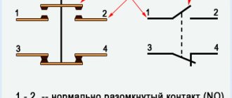
Set the core voltage designation which is mentioned on it and not on the starter. It consists of two buttons: normally open for turning on; normally closed to turn off. It's the easiest thing to deal with.
The starter starts turning on with the closing of the normally open contacts and the opening of the normally closed ones. This is an important aspect, because if connected incorrectly, the core may burn out or will not fully start the necessary contactors.
A good example. Our readers recommend! The fixed part is the lower one and is fixed to the body, the upper one is spring-loaded and can move freely.
In this case, even with a certain complexity of the circuit, connecting it will not be difficult at all. Preparation for assembly Before directly assembling the circuit for connection, you need to: Free the working area from current and check that there is no voltage with a tester. It includes two pairs of contact groups consisting of normally closed and normally open contacts.
How does it work
The magnetic starter can be turned off via the STOP button, while the voltage is removed from the control coil and the springs return the contacts to their original position. Magnetic starters are designed for small currents - up to 10 amperes, which are used when operating all types of electrical equipment.
The contacts of the magnetic starter are manipulated by means of a control pulse. Ultimately, the moving contacts close, and the mains voltage at V goes to the load. Operation of the Power Circuit The responsibility for switching phases to redirect the rotation of the motor rests with the power circuit. Contactor operating principle and connection diagram
Operating principle of contactor
Externally, the contactor is a coil of wires, inside of which there is a core, or cylinder, mechanically connected to the electrical closing and opening contacts. Closing contacts close the circuit through which current flows, and opening contacts, on the contrary, open it, stopping the current. A thin-walled frame made of copper or steel provides mechanical strength to the coil and optimal conditions for cooling the device elements.
The operation of a contactor is based on two opposing actions. Voltage is applied to the electromagnetic coil, after which the core, under the influence of the magnetic field, begins to move upward, and the circuit is closed, which leads to the appearance of current in the circuit and the inclusion of an electric motor or other connected equipment. After turning off the power supply, thanks to the spring system, the core returns to its original position, the main circuit opens, and the electrical equipment is turned off.
The contactor is turned on and off using a push-button device with two buttons - “Start” in black and “Stop” in red. When you press the “Start” button, the contacts connected to the button close, and when you press the “Stop” button, they open. Closing the contacts leads to the supply of voltage to the contactor coil and the closure of power contacts in it, which remain in the on state, even after the button returns to its original position - thanks to the auxiliary block contacts.
There is a fundamental difference in the names of the circuits involved in the operation of the system. The coil receives power from the control circuit, the voltage in which can be very different - most often 230 V. In turn, the circuit in which the contact is closed is called the power circuit, since it passes a current of greater strength than the current in the control circuit.