Hello, dear readers of the site. At the beginning of their studies in radio electronics, beginning radio amateurs, and not only radio amateurs, have a lot of questions related to the continuity or determination of transformer windings . This is good if the transformer has only two windings. And if there are several of them, and each winding also has several outputs. Here you just shout guard. In this article I will tell you how you can determine the windings of a transformer by visual inspection and using a multimeter.
As you know, transformers are designed to transform
alternating voltage of one magnitude into alternating voltage of another magnitude.
The most common transformer has one primary
and one
secondary
winding. The supply voltage is supplied to the primary winding, and the load is connected to the secondary winding. In practice, most transformers can have several windings, which makes it difficult to determine them.
How to ring a commutator motor
The collector unit can also be tested with a multimeter.
This type of electric motor is used in a DC circuit. Brushed AC motors are less common, such as in various power tools. The best way to ring such products is to completely disassemble the electric motor.
You can check the armature of the electric motor, as well as ring the stator winding, using a multimeter, which must be switched to resistance measurement mode up to 200 Ohms.
Most often, the stator of a collector unit consists of two independent windings, which need to be tested with a multimeter to determine their serviceability.
The exact value of this indicator can be found in the documentation for the electric motor, but the performance of the winding can be judged if the device shows a small resistance value.
In powerful DC motors of car electrical equipment, the stator resistance value will be so small that its difference from a short-circuited conductor can be tenths of an ohm. Less powerful devices have a stator winding resistance in the range of 5 - 30 Ohms.
In order to ring the stator windings of a commutator motor with a multimeter, it is necessary to connect the probes of the measuring device to the terminals of these windings. If during diagnostic activities a lack of resistance is detected even in one circuit, further operation of the unit is not carried out.
The rotor of a commutator motor consists of a significantly larger number of windings, but checking the armature will not take much time.
In order to ring this part, you need to turn on the multimeter in resistance measurement mode up to 200 Ohms and place the multimeter probes on the collector so that they are at the maximum distance from each other.
In this way, the probes will take the place of the motor brushes and one of the several armature windings can be ringed. If the multimeter shows any value, then without removing the probes of the measuring device from the collector, you should turn the rotor slightly until the next winding is connected to the probes of the device.
Starting and running windings of a single-phase motor: how to distinguish?
This way you can check the winding without much effort. If the multimeter shows approximately the same resistance value for each circuit, this will mean that the armature of the device is absolutely working.
This violation can lead not only to failure of the electric motor, but also to an increased likelihood of electrical injury. Checking the armature and stator of a commutator motor for breakdown is not difficult; to do this, you need to turn on the mode for measuring resistance up to 2,000 kOhm. To check the stator, it is enough to connect one terminal to the housing and the second to one of the windings.
To ring this part of the electric motor correctly, during this operation it is forbidden to touch the metal part of the multimeter probes, or the stator housing and the wiring of the circuit being measured.
If you do not adhere to this rule, you can get false positive results, since sufficient electrical potential will pass through the human body. In this case, the multimeter will show human resistance, and not a “breakdown” between the stator housing and the winding.
The possible leakage of electric current to the armature housing of the electric motor is measured in a similar way.
To determine the absence of a “breakdown” to the ground of the device, it is necessary to alternately connect the multimeter probes to the housing and various windings of the electric motor rotor.
In order to test different types of electric motors using a multimeter, you need to purchase a multimeter that has a resistance measurement mode.
Ultra-precision is not required when carrying out such actions, so you can successfully use cheap Chinese devices. Before you test the motor windings with a multimeter, you need to make sure it is working properly.
It should also be borne in mind that an electric motor malfunction can have various symptoms. Even if the electrical device is in working condition, but the engine speed does not reach the maximum value, you should immediately check for possible damage to the windings.
How to check the health of a three-phase asynchronous motor
When carrying out any electrical installation or diagnostic work, it is necessary to completely disconnect the device from the 220 V network or three-phase current.
How to distinguish on a single-phase motor
Single-phase motors are equipped with two types of winding so that their rotor can rotate, since only one is not enough for this. Therefore, before connecting the motor, you need to figure out which skein is the main one and which is the auxiliary one. There are several ways to do this.
By color coding
What type a particular skein is can be determined by color markings during a visual inspection of the engine. As a rule, red wires are of the working type, but blue wires are of the auxiliary type.
But all rules have their exceptions, so you should always pay attention to the electric motor tag, on which a decoding of all markings is applied
However, if the engine has already been repaired or there is no tag on it, this method of checking is not effective. In the first case, during repair work, the internal contents of the motor could completely change, and in the second, there is no way to accurately decipher the color symbols. In addition, sometimes there may be no markings at all. Therefore, in such situations, it is better to resort to another, more reliable method.
By wire thickness
The thickness of the wires that come out of a low-power electric machine will help distinguish the starting coil from the working one. Since the auxiliary one works for a short time and does not experience serious load, the wires related to it will be thinner.
But even if it catches your eye, you shouldn’t rely on that alone. Therefore, many always measure the resistance of wires.
Using a multimeter
A multimeter is a special device that allows you to measure the resistance of wires, as well as their integrity. To do this, you must follow the following algorithm:
- Take a multimeter and select the desired function.
- Remove the insulation from the motor wires and connect any two of them to the probes of the device. This is how the resistance force between the two motor wires is measured.
- If no numerical values appear on the device screen, then you need to replace one of the wires and then repeat the procedure. The readings obtained will refer to the terminals of one skein.
- Connect the probes of the measuring device to the remaining wires and record the readings.
- Compare your results. Electrical wires with a stronger resistance will belong to the starting coil, and those with a weaker resistance will belong to the working coil.
Once the measurements have been determined and it becomes clear which electrical wires belong to which coil, it is recommended to mark them in any convenient way. This will allow you to skip the resistance measurement procedure when connecting the motor in the future.
How to rewind an asynchronous motor at home
There are several ways to distinguish where the starting winding is and where the working winding is of a single-phase motor. However, the most effective of them is to measure the resistance of the electrical wires coming from a low-power electric motor using a multimeter.
Repair of asynchronous motors
The most common are asynchronous power units with two and three phases. The procedure for diagnosing them is not exactly the same, so this should be discussed in more detail.
Three phase motor
There are two types of malfunctions of electrical units, regardless of their complexity: the presence of a contact in the wrong place or its absence.
A three-phase AC motor has three coils that can be connected in a delta or star shape. There are three factors that determine the performance of this power plant:
- Correct winding.
- Insulation quality.
- Reliability of contacts.
A short to housing is usually checked using a megohmmeter, but if you don’t have one, you can get by with a regular tester, setting it to the maximum resistance value - megohms. In this case there is no need to talk about high accuracy of measurements, but it is possible to obtain approximate data.
Before measuring resistance, make sure that the motor is not connected to the mains, otherwise the multimeter will become unusable. Then you need to calibrate by setting the arrow to zero (the probes must be closed). It is necessary to check the serviceability of the tester and the correctness of the settings by briefly touching one probe to another each time before measuring the resistance value.
Place one probe on the motor housing and make sure there is contact. After this, take the readings of the device by touching the engine with the second probe. If the data is within normal limits, connect the second probe to the output of each phase in turn. A high resistance value (500-1000 or more megohms) indicates good insulation.
How to check the insulation of windings is shown in this video:
Motor insulation resistance measurement
Then you need to make sure that all three windings are intact. You can check this by ringing the ends that go into the motor terminal box. If a break in any winding is detected, diagnostics should be stopped until the fault is eliminated.
How to ring an electric motor
The next check point is the determination of short-circuited turns. Quite often this can be seen during a visual inspection, but if externally the windings look normal, then the fact of a short circuit can be determined by the unequal current consumption.
Two-phase electric motor
Diagnostics of power units of this type is somewhat different from the procedure described above. When checking a motor equipped with two coils and powered from a regular electrical network, its windings must be tested using an ohmmeter. The resistance of the working winding should be 50% less than that of the starting winding.
The resistance to the housing must be measured - normally it should be very large, as in the previous case. A low resistance indicator indicates the need to rewind the stator. Of course, to obtain accurate data, it is better to carry out such measurements using a megger, but such an opportunity is rarely available at home.
Checking commutator electric motors
Having dealt with the diagnostics of asynchronous motors, let’s move on to the question of how to ring an electric motor with a multimeter if the power unit is of the commutator type, and what are the features of such checks.
To properly check the performance of these motors using a multimeter, you need to proceed in the following order:
- Turn on the Ohm tester and measure the resistance of the collector lamellas in pairs. Normally, these data should not differ.
- Measure the resistance indicator by placing one probe of the device on the armature body and the other on the commutator. This indicator should be very high, approaching infinity.
- Check the stator for winding integrity.
- Measure the resistance by applying one probe to the stator housing and the other to the terminals. The higher the score obtained, the better.
It will not be possible to check the electric motor with a multimeter for an interturn short circuit. For this, a special apparatus is used to check the anchor.
Checking power tool motors is shown in detail in this video:
How to check a commutator motor with a multimeter - stator and rotor windings
Ohmic resistance - winding
By measuring the ohmic resistance of the transformer windings and comparing the obtained values with factory data, areas with soldering failures and wire breaks are identified.
The ohmic resistance of the windings is measured using the resistance method (voltmeter and ammeter), which, when using devices of class 0 2 or 0 5, ensures high accuracy. A voltmeter that measures the voltage drop is connected directly to the terminals of the winding being measured. The voltmeter is connected to the armature winding with special probes installed on the commutator plates located between the brushes. Ohmic resistance is measured before testing the machines (in a practically cold state); the resulting value is recalculated to a temperature of 20 C. The resistance should not differ from the nominal (certificate) value by 10% for repaired machines.
The ohmic resistance of the windings is measured using a bridge, as described in Chapter X.
| Measuring resistance using the voltmeter and ammeter method. |
Measurement of ohmic resistance of machine windings and ballasts is carried out using the voltmeter and ammeter method or a bridge with the engine stopped.
Since the ohmic resistance of the traction motor windings is very small (hundredths of an ohm), the product is also insignificant and can be neglected.
It is also necessary to measure the ohmic resistance of the windings of built-in (sleeve) current transformers on all taps, relay windings, transition resistances of contact connections that are not accessible for inspection, and individual contact connections that raise doubts about their quality
Particular attention should be paid to plug and sliding contact connections, for example contacts by which secondary elements of the switchgear cell trolley are connected to secondary elements located in fixed compartments.
| Curves of limit values of the no-load current ratio of three-phase asynchronous motors. |
To do this, it is necessary to check the ohmic resistance of the winding, the serviceability of the rotor squirrel cage, the correct axial displacement of the rotor steel in relation to the stator, the size of the gap between the rotor and stator steel in comparison with the prescribed one, the correct connection of the stator winding circuit and the amount of heating of the bearings.
We find the voltage drop in the ohmic resistance of the winding: / g 0 V.
To obtain a sufficient transformation ratio, the ohmic resistance of the windings must be small, which forces one to choose k.
| Circuit for measuring the ohmic resistance of the windings of an asynchronous electric motor. |
The adjusting rheostat g allows you to measure the ohmic resistance of the windings at various voltages and currents.
| Schemes for drying an asynchronous motor with direct current. a and b - if there are six winding terminals. vig - if there are three winding terminals. |
The amount of required voltage is determined by the ohmic resistance of the winding and the required current strength. The power supply circuit must provide for current regulation and long-term operation.
Ohm's law.
And here the fundamental law of all electronics – Ohm’s law – comes to our aid:
The current in a circuit is directly proportional to the voltage and inversely proportional to the resistance of the section of the circuit in question.
Let's consider the simplest electrical circuit: As follows from Ohm's law, the voltage and current in the circuit are related as follows:
I = frac{U}{R}
Let the voltage be 10 V and the circuit resistance be 200 ohms. Then the current in the circuit is calculated as follows:
I = frac{10}{200} = 0.05 = 50medspacemA
How to use a megohmmeter correctly?
To carry out testing, it is important to correctly set the measurement ranges and test voltage level. The easiest way to do this is to use special tables that indicate parameters for various tested objects
An example of such a table is given below.
Table 1. Correspondence of the voltage level to the permissible insulation resistance value.
| Test object | Voltage level (V) | Minimum insulation resistance (MOhm) |
| Checking the electrical wiring | 1000,0 | 0,5> |
| Household electric stove | 1000,0 | 1,0> |
| RU, Electrical panels, power lines | 1000,0-2500,0 | 1,0> |
| Electrical equipment powered up to 50.0 volts | 100,0 | 0.5 or more depending on the parameters specified in the technical data sheet |
| Electrical equipment with rated voltage up to 100.0 volts | 250,0 | 0.5 or more depending on the parameters specified in the technical data sheet |
| Electrical equipment powered up to 380.0 volts | 500,0-1000,0 | 0.5 or more depending on the parameters specified in the technical data sheet |
| Equipment up to 1000.0 V | 2500,0 | 0.5 or more depending on the parameters specified in the technical data sheet |
Let's move on to the measurement technique.
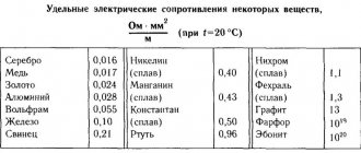
Table of resistivities of various materials
| Specific resistance ρ, Ohm*mm2/m | Specific resistance ρ, Ohm*mm2/m |
| Aluminum | 0,028 |
| Bronze | 0,095 – 0,1 |
| Bismuth | 1,2 |
| Tungsten | 0,05 |
| Iron | 0,1 |
| Gold | 0,023 |
| Iridium | 0,0474 |
| Constantan (Ni-Cu + Mn alloy) | 0,5 |
| Brass | 0,025 – 0,108 |
| Magnesium | 0,045 |
| Manganin (alloy of copper, manganese and nickel – instrument) | 0,43 – 0,51 |
| Copper | 0,0175 |
| Molybdenum | 0,059 |
| Nickel silver (an alloy of copper, zinc and nickel) | 0,2 |
| Sodium | 0,047 |
| Nickelin (an alloy of copper and nickel) | 0,42 |
| Nickel | 0,087 |
| Nichrome (an alloy of nickel, iron chromium and manganese) | 1,05 – 1,4 |
| Tin | 0,12 |
| Platinum | 0.107 |
| Mercury | 0,94 |
| Lead | 0,22 |
| Silver | 0,015 |
| Steel | 0,103 – 0,137 |
| Titanium | 0,6 |
| Hromal | 1,3 – 1,5 |
| Zinc | 0,054 |
| Cast iron | 0,5-1,0 |
Winding insulation resistance measurement
To test a motor for insulation resistance, electricians use a megger with a test voltage of 500 V or 1000 V. This device measures the insulation resistance of motor windings designed for an operating voltage of 220 V or 380 V.
For electric motors with a rated voltage of 12V, 24V, a tester is used, since the insulation of these windings is not designed for testing under the high voltage of 500 V megger. Typically, the motor data sheet indicates the test voltage when measuring the insulation resistance of the coils.
Insulation resistance is usually checked with a megger
Before measuring the insulation resistance, you need to familiarize yourself with the connection diagram of the electric motor, since some star connections of the windings are connected at a midpoint to the motor housing. If the winding has one or more connection points, delta, star, single-phase motor with starting and running windings, then the insulation is checked between any connection point of the windings and the housing.
If the insulation resistance is significantly less than 20 MΩ, the windings are disconnected and each is checked separately. For a complete motor, the insulation resistance between the coils and the metal casing must be at least 20 MΩ. If the motor has been operated or stored in damp conditions, then the insulation resistance may be below 20 MΩ.
Then the electric motor is disassembled and dried for several hours with a 60 W incandescent lamp placed in the stator housing. When measuring insulation resistance with a multimeter, set the measurement limit to the maximum resistance, megohms.
Insulation testing methods
Before applying voltage, to prevent a short circuit, it is necessary to check the insulation between live parts and the body of the electric machine. In three-phase electric motors, the windings are interconnected. To check that there is no short circuit between them, if possible, the windings should be disconnected from each other. The insulation of each of them is checked relative to the other coils and the machine body. The insulation is checked with a megger. For this output, the device is connected to the “megaohm” position. The ends are applied to the terminals and part of the body, which has been stripped of paint.
Information! Instead of a housing, the output can be attached to the shaft of an electric machine.
The measurement is carried out by two people - one person applies the device’s output to the measured elements, and the second turns the device’s handle for a minute, then, without stopping the rotation, readings are taken. If the result is questionable, the measurement should be repeated. Wires and windings have electrical capacitance and are charged from the megger during measurement, therefore, after completing the tests or before re-checking the output of the device and the parts being measured, it is necessary to discharge them by short-circuiting.
How to test an electric motor with a multimeter
To identify an electric motor malfunction at home, in the absence of expensive professional equipment, there is nothing left to do but test the electric motor with a multimeter. With its help, you can identify most breakdowns, and you do not have to involve a specialist. So what should you do?
Preparation
Before making a diagnosis, you should:
- De-energize the unit. If the resistance measurement is carried out in a circuit connected to the mains, the device will fail.
- Calibrate the device, that is, set the arrow to the zero position (the probes must be closed).
- Inspect the engine and find out if it is flooded, if there is a smell of burnt insulation or broken parts, etc.
Asynchronous, commutator, single-phase and three-phase motors are called using the same method; a slight difference in the design does not play a special role, but there are nuances that must be taken into account.
Stages of work
The most common malfunctions can be divided into two types:
- Presence of contact in a place where there should not be one.
- Lack of contact where it should be.
First, let's look at how to test a 3-phase electric motor with a multimeter. It has three coils connected in a delta or star configuration. Its performance is affected by the reliability of contacts, the quality of insulation and correct winding.
- First, check the short circuit to the body (keep in mind, the value will be approximate, since more sensitive instruments are required for accurate readings).
- Set the multimeter readings to maximum.
- Connect the probes to each other to ensure that the settings are correct and the device is working properly.
- Connect one of the probes to the engine housing; if there is contact, attach the second probe to the housing and monitor the readings.
- If there are no failures, touch the probe output of each of the three phases one by one.
- If the insulation is of high quality, the test should show a fairly high resistance (several hundred or thousand megohms).
It must be remembered that when measuring insulation resistance using a multimeter, the readings will be higher than permissible, since the EMF of the device does not exceed 9V. The engine operates at 220 or 380V. According to Ohm's law, the resistance value depends on the voltage, so make allowances for the difference.
Next, check the integrity of the windings by ringing the three ends included in the motor boron. If there is a break, further checking does not make sense, since this malfunction must first be eliminated.
Then check for shorted turns. With a delta connection, the fault indicator will be a higher value at ends A1 and A3. When connected with a star, the device shows an overestimated value in circuit A3.
Important
Knowing how to test an asynchronous electric motor with a multimeter, you will save time and money, since perhaps only minor faults will be detected that you can easily fix yourself.
For more serious and detailed diagnostics, other devices are required, which are rarely used in everyday life due to their high cost.
If you are unable to find damage with a multimeter, contact a professional.
Checking the commutator motor
Now let's move on to the above-mentioned nuances, because engines come in different types. How to test a commutator motor with a multimeter? The scheme for checking it looks like this:
- Turn on the device in Ohm units and measure the resistance of the collector lamellas in pairs.
- Then measure the resistance between the armature housing and the commutator.
- Check the stator windings.
- Measure the resistance between the housing and the stator terminals.
Interturn closure is determined only by a special device. There is a way to measure armature resistance. Remove the brushes from it and apply a voltage of up to 6V to the plates, measure the voltage drop between them.
To check a single-phase motor, ring the working and starting windings. The resistance of the first should be one and a half times lower than the second.
For example, let's take a single-phase motor with three terminals, used in washing machines (usually the old model). If there is very high resistance between the ends, then the coils are connected in series. It remains to find the midpoint and thus determine the ends of each of them separately.
Since electric motors are found in every home in household appliances - this is a refrigerator, a vacuum cleaner, and much more - and they periodically break down, knowing how to check a single-phase electric motor with a multimeter is simply necessary. If the damage is not too serious, it is not advisable to take the device to a repair shop. And you will have the opportunity to gain experience and gain skills by working with engines of different types and modifications.
Ohm's law for a circuit section
With pebbles in a pipe, everything is clear, but not only does the force with which the flow of water flows through the pipe depend on them, it also depends on the pump with which we pump this water. The harder we pump, the stronger the current. In an electrical circuit, the pump function is performed by a current source.
For example, the source may be a galvanic cell (a conventional battery). A battery works based on chemical reactions inside it. These reactions release energy, which is then transferred to the electrical circuit.
Any source necessarily has poles - “plus” and “minus”. The poles are its extreme positions, essentially the terminals to which the electrical circuit is connected. Actually, the current flows from “+” to “-”.
We already have two quantities on which the electric current in the circuit depends - voltage and resistance. It seems it is time to combine them into law.
The current strength in a section of a circuit is directly proportional to the voltage at its ends and inversely proportional to its resistance.
Mathematically it can be described like this:
| Ohm's law for a circuit section I = U/R I - current strength [A] U - voltage [V] R - resistance [Ohm] |
Voltage is measured in Volts and shows the difference between two points in the circuit: this difference determines how much current will flow - the greater the difference, the higher the voltage and the stronger the current will flow.
Current strength is measured in Amperes, and you can read more about it in our article
Let's solve several problems using Ohm's Law for a section of a circuit.
Task times
Find the current strength in an incandescent light bulb if the floor lamp is connected to a 220 V network and the resistance of the filament is 880 Ohms.
Solution:
Let's take Ohm's law for a section of the circuit:
I = U/R
Let's substitute the values:
I = 220/880 = 0.25 A
Answer: The current passing through the light bulb is 0.25 A
Let's make it more difficult. And we will find the current strength, I know all the parameters for calculating the resistance and voltage.
Problem two
Find the current strength in an incandescent light bulb if the floor lamp is connected to a 220 V network, and the length of the filament is 0.5 m, the cross-sectional area is 0.01 mm^2, and the resistivity of the filament is 1.05 Ohm*mm^2/ m.
Solution:
First, let's find the resistance of the conductor.
R = ρl/S
The area is given in mm^2, and the resistivity also contains mm^2 in dimension.
This means that you can substitute values without converting to SI:
R = 1.05*0.5/0.01 = 52.5 Ohm
Now let's take Ohm's law for a section of the circuit:
I = U/R
Let's substitute the values:
I = 220/52.5 ≃ 4.2 A
Answer: The current passing through the light bulb is approximately 4.2 A
Now let's make it even more complicated! Let's determine the material from which the filament is made.
Problem three
What material is the filament of the light bulb made of, if the table lamp is connected to a 220 V network, the length of the filament is 0.5 m, its cross-sectional area is 0.01 mm^2, and the current in the circuit is 8.8 A
Solution:
Let's take Ohm's law for a section of the circuit and express the resistance from it:
I = U/R
R = U/I
Let's substitute the values and find the resistance of the thread:
R = 220/8.8 = 25 Ohm
Now let’s take the resistance formula and express the resistivity of the material from it:
R = ρl/S
ρ = RS/l
Let's substitute the values and get:
ρ = 25*0.01/0.5 = 0.5 Ohm*mm^2/m
Let's refer to the material resistivity table to find out what material this filament is made of.
Checking the bearings
The movement of the rotor relative to the stator is possible thanks to bearings. They can be structurally implemented on one of the principles:
- slip,
- rolling.
The ease of rotation of the shaft and rotor of an electric motor is the first point of checking any engine. To put it into practice, you need to:
- disconnect the motor being tested from the power source or electrical network;
- holding the shaft with your hand, shake it back and forth or turn the rotor.
Assessing the condition of the bearings But since motors are often part of an electric drive with a gearbox, you need to know for sure that the shaft you are holding is part of the rotor, not the gearbox.
Some gear reducers, with a certain force, still allow their shaft to be rotated, and in this way the condition of the bearings can be assessed. But many globoids and worms do not. In this case, you must try to gain access to the motor shaft inside the gearbox. Better yet, disconnect the gearbox from the engine if possible. If rotation is difficult, then the bearing is faulty for the following reasons:
- its service life has expired due to wear of the working elements;
- There is either too little lubrication or no lubrication at all. But it may also be that a lubricant that does not meet the operating conditions was used. For example, some of its varieties become so thick at temperatures below zero that they slow down rotation. In this case, the bearings are washed with gasoline and the lubricant is replaced with another one suitable for these conditions.
- The gaps between the rubbing elements of the bearing are clogged with dirt. It is also possible that small foreign objects may enter.
Broken ball bearing
Ohm's law for a complete circuit
We have dealt with Ohm's law for a section of a circuit. Now let's find out what happens if the circuit is complete: it has a source, conductors, resistors and other elements.
In this case, Ohm's Law is introduced for a complete circuit: the current strength in a complete circuit is equal to the ratio of the EMF of the circuit to its total resistance.
EMF stands for electromotive force. It is denoted by the Greek letter ε and is measured, like voltage, in Volts.
- EMF is the force that moves charged particles in a circuit. It is taken from the current source. For example, from a battery.
A chemical reaction inside a galvanic cell (this is synonymous with a battery) occurs with the release of energy into an electrical circuit. It is this energy that causes particles to move along the conductor.
Voltage and EMF are often equated and said to be the same thing. Formally, this is not so, but when solving problems, most often there really is no difference, since these quantities are both measured in Volts and define processes that are very similar in essence.
In the form of a formula, Ohm's Law for a complete circuit will look like this:
| Ohm's law for a complete circuit I = ε/(R + r) I - current strength [A] ε - EMF [V] R - resistance [Ohm] r - internal source resistance [Ohm] |
No source is perfect. In problems this is possible (“consider the source ideal,” these are the phrases), but in real life it’s definitely not. In this regard, the source has internal resistance, which prevents the flow of current.
Let's solve the problem for a complete circuit.
Problem
Find the current in a complete circuit consisting of one resistor with a resistance of 3 Ohms and a source with an emf equal to 4 V and an internal resistance of 1 Ohm
Solution:
Let's take Ohm's law for a complete circuit:
I = ε/(R + r)
Let's substitute the values:
I = 4/(3+1) = 1 A
Answer: The current in the circuit is 1 A.
Which electric motors can be checked with a multimeter?
If the motor does not have obvious external damage, then there is a possibility that an internal open circuit or short circuit has occurred. But not all electric motors can be simply checked for these defects with a multimeter.
For example, difficulties may arise in diagnosing DC electric motors, since their winding has practically zero resistance and it can only be checked indirectly using a special scheme: readings are simultaneously taken from an ammeter and a voltmeter and the resulting resistance value is calculated using Ohm’s law.
In this way, all resistance of the armature windings is checked and the values between the collector plates are measured. If the resistances of the armature windings differ, then there is a problem, since in a working machine these values are the same. The difference in resistance values between adjacent collector plates should be no more than 10%, then the engine will be considered serviceable (but if the design includes an equalizing winding, then this value can reach up to 30%).
AC electrical machines are divided into:
- synchronous: having stator windings located at the same displacement angle among themselves, which allows movement at a frequency synchronous with the rotation speed of the applied force;
- asynchronous with squirrel-cage rotor (single- or three-phase);
- asynchronous with a wound rotor, having a three-phase winding;
- collector
All these types of engines are available for diagnostics using measuring instruments, including multimeters. In general, AC motors are fairly reliable machines and malfunctions in them are quite rare, but they do happen.
How does a transformer work and what is it for?
A transformer is one of the elementary electrical devices. The principle of its operation is based on the excitation of a magnetic field and its two-way transformation.
Important! A magnetic field can only be induced on the core using alternating current. Therefore, there are no transformers operating on direct current. If it is necessary to convert direct voltage, it is first made alternating or pulsed. For example, using master oscillators.
A primary winding is wound around a single magnetic core, to which an alternating voltage with primary characteristics is supplied. An alternating voltage is induced on the remaining windings wound on the same core. The difference in the number of turns in relation to the primary determines the transmission coefficient.
Reasons for low resistance
There are several reasons for low insulation resistance.
Electric machine overheating
This situation occurs due to an overload of the electric machine or a break in one of the phases in three-phase electric motors. It is impossible to eliminate this problem in a workshop and the device must be sent to a specialized enterprise to replace the windings.
Protection devices help prevent such a malfunction:
- The thermal relay turns off the electric machine when overloaded;
- The voltage relay turns off the installation if one of the phases is missing or the network voltage is low.
Important! For better protection, temperature sensors are built inside electric motors. In new machines they are installed during manufacture, and in old machines such devices can be installed during planned or major repairs. Source
Source
Checking an asynchronous electric motor
In addition to commutator motors, in everyday life you can also find asynchronous motors installed in some models of washing machines or in refrigerator compressors. Much more often they are used in compressors, pumps, various machines and other equipment. Despite their high reliability, these electric motors are also susceptible to breakdowns and malfunctions. In these designs, the role of the armature is played by the stator windings, so visual inspection should begin with them.
Often the windings stop working when they become damp or the turns break. Therefore, if the motor has not been used for a very long time, it is necessary to check the insulation resistance using a megger. In the absence of a mgohmmeter, for preventive purposes it is recommended to disassemble the unit and dry the stator windings for several days.
It is quite possible that the cause of the malfunction does not lie in the electric motor itself, but is associated with some other factors. Therefore, before you start repairing the unit itself, you should make sure that there is voltage, check the magnetic starters, connection cables, and thermal relay. If there is a capacitor in the circuit, it also needs to be checked. If all of the above elements are in good working order, you can begin disassembling the engine for initial inspection. The test must be carried out in a complete absence of power supply. It is necessary to prevent spontaneous or erroneous switching on of the unit.
During the inspection, in addition to other parts, the stator windings are especially carefully checked. They must be intact, without protruding or torn wires
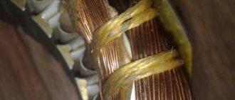
Particular attention should be paid to black spots indicating possible burnt wires. In good condition, the conductors are dark red in color.
Blackening occurs when the electrical insulating varnish applied to their surface burns out. During inspection, complete or partial burnout of the winding and interturn short circuit may be detected. With partial burnout, the engine will run and heat up quickly. Therefore, the winding is completely rewound in any case.
If the external examination does not produce results, further diagnostics should be carried out using measuring instruments. Most often, a multimeter is used for these purposes to determine the integrity of the winding and the presence or absence of a breakdown in the housing.
In 220V engines, the starting and operating windings are connected. The starting resistance should be 1.5 higher than that of the working one. In 380V electric motors connected by star or delta, the circuit is disassembled, after which each winding is wired in turn. The resistance on each of them should be the same, with a deviation of no more than 5%. Also, all windings must be connected to each other and to the housing. If the resistance value is not infinite, this indicates the presence of a breakdown of the windings on the housing or between themselves. In this case, they require a complete rewind.
The insulation resistance of the motor windings is checked separately. In this case, a multimeter will not help; you will need a 1000V megohmmeter connected to a separate power source. When performing measurements, one wire of the device touches the motor body in an unpainted place, and the other wire is connected in turn to each terminal of the winding. If the insulation resistance is less than 0.5 megohm, then the motor requires drying
When taking measurements, be careful not to touch the test leads. The equipment being measured must be de-energized, the duration of measurements is at least 2-3 minutes
Read also: Is it possible to connect running lights to the dimensions
The greatest difficulty is the search for interturn closure. It cannot be detected by visual inspection. For three-phase motors, special inductance meters are used, which normally show the same value on all windings. If there is damage, the inductance of such a winding will be the lowest.
During the operation of any equipment, breakdowns of various types periodically occur that require high-quality repairs. Electric motors that are common today are no exception. Such units can fail as a result of an interturn short circuit. In such a situation, a seemingly serviceable engine may burn out. That is why specialists try to promptly determine the interturn type short circuit in order to qualitatively eliminate the cause of the malfunction.