LEDs, which appeared on the radio electronics market relatively recently, have already firmly taken a leading position in relation to other light sources. They are the most economical in terms of energy consumption, more compact and convenient to use and have less heat generation.
And yet, no matter how high-tech the LED is, an increase in temperature during its operation cannot be avoided. In addition, when heated, such an LED element, due to its design features, begins to lose its luminous flux.
Of course, if it is a regular DIP LED with two contact legs, external cooling is quite enough for it. But if we take more powerful elements, then it’s worth thinking about a cooling radiator for LEDs, which would help remove heat from the light source.
If you pay attention to similar cooling devices in stores, you can understand how high their cost is. What to do then?
It remains to figure out whether it is possible to make a radiator for a specific LED or group of LEDs yourself, how to do it, and how difficult it is. Now we will try to resolve this issue.
Temperature dependencies
As the temperature of the LED crystal increases, along with a decrease in the luminous flux, the forward voltage and, as a result, power consumption decrease.
The drop in power partially compensates for the decrease in luminous flux, and efficiency drops slowly with temperature - this must be taken into account. Example 1
Graph of efficiency versus temperature of LEDs released more than three years ago, LXM8-PW27 and LXM8-PW30, shown in the Philips Lumileds DS63 documentation (Fig. 1). Efficiency increases up to +25…+50 °C and does not decrease significantly up to a temperature of +75 °C.
Rice. 1. Graph of LED efficiency versus chip temperature from Philips Lumileds DS63 technical documentation
Example 2
The technical documentation for the Osram OSLON Square LED (LCW_CQAR.PC) provides detailed graphs of the dependence of forward voltage and luminous flux on temperature. If you multiply the values from these two graphs, you get the dependence of relative efficiency on temperature (Fig. 2). Efficiency remains virtually unchanged up to a crystal temperature of +85 °C.
Rice. 2. Dependence of the relative efficiency of the Osram OSLON Square LED (LCW_CQAR.PC) on the crystal temperature
Example 3
Cree, in its technical documentation for LEDs, provides graphs of the dependence of luminous flux on temperature, approximating complex dependences by linear ones, and gives the average coefficient of temperature dependence of voltage. This does not determine the temperature up to which efficiency does not decrease, but it does provide an estimate of "on average" how much efficiency will decrease as the temperature increases. With an increase in chip temperature by 10 ° C, the luminous flux of various Cree LEDs decreases by 2–2.5%, forward voltage by 20–30 mV, power consumption by 0.7–1.0%, efficiency by 1.0 -1.5%.
For further assessments, we will use the average values of these ranges: with an increase in temperature by 10 °C, the luminous flux decreases by 2.25%, forward voltage by 25 mV, power consumption by 0.85%, and efficiency by 1.25%.
Introduction
LED lamps have firmly entered our lives; they can be found in almost every home, in enterprises, in various institutions, and on the street.
They help save energy, are reliable, have a long service life, as well as a whole set of technical characteristics that give these lamps an advantage over lighting devices of previous generations.
LED fixtures produce less heat than most fixtures with other light sources. But, nevertheless, during operation of the device, natural heating of the LEDs occurs. If the heat dissipation is poor, the temperature of the LEDs may be higher than permissible for their normal operation. If the elevated temperature of the LEDs remains constant, after some time the phosphor will degrade and the color temperature of the diodes will change. The luminous flux will also decrease, while energy consumption will remain the same, that is, energy efficiency will decrease, and the service life of the lamp will noticeably decrease.
Target heatsink temperature
The temperature of the crystal is calculated as the sum of the temperature of the board next to the LED (solder points) and the product of the thermal resistance of the case and the thermal power generated by the LED. More powerful LEDs naturally have a lower thermal resistance of the housing, while less powerful ones have a higher one. But the product of thermal resistance and power usually remains within 10–15 °C. Due to some temperature inhomogeneity between the board and the radiator, we can assume that the radiator is on average 5–10 °C cooler than the board and about 20 °C cooler than the crystal. Therefore, the target heatsink temperature is 20 °C lower than the target die temperature.
Let us take into account that in the description of all modern LEDs, temperatures of at least +120 °C are indicated as operating temperatures; at radiator temperatures up to +100 °C, only the dependence of the LED efficiency on temperature should be taken into account.
It is reasonable to take the highest value as the target temperature of the crystal, up to which there is no significant decrease in efficiency. For any specific diodes intended for use, this value can be clarified. For example, let’s take a very conservative value for the target temperature of the crystal - +75 ° C and, accordingly, the target temperature of the radiator +55 ° C. This value is convenient because it is easy to control manually: most people cannot keep their finger on a metal surface with a temperature above +50...+60 °C, and lower temperatures are perceived as tolerable.
Why is it needed?
Along with other semiconductor devices, the LED is not an ideal element with 100% efficiency. Most of the energy it consumes is dissipated into heat. The exact efficiency value depends on the type of emitting diode and its manufacturing technology. The efficiency of low-current LEDs is 10-15%, and for modern white ones with a power of more than 1 W, its value reaches 30%, which means that the remaining 70% is spent as heat.
Whatever the LED, for stable and long-term operation it requires a constant removal of thermal energy from the crystal, that is, a radiator. In low-current LEDs, the radiator function is performed by the leads (anode and cathode). For example, in SMD 2835 the anode lead takes up almost half of the bottom of the element. In high-power LEDs, the absolute value of power dissipation is several orders of magnitude greater. Therefore, they cannot function normally without an additional heat sink. Constant overheating of the light-emitting crystal significantly reduces the service life of the semiconductor device and contributes to a gradual loss of brightness with a shift in the operating wavelength.
Structurally, all radiators can be divided into three large groups: plate, rod and ribbed. In all cases, the base can be in the shape of a circle, square or rectangle. The thickness of the base is of fundamental importance when choosing, since it is this area that is responsible for receiving and uniformly distributing heat over the entire surface of the radiator.
The form factor of the radiator is influenced by the future operating mode:
- with natural ventilation;
- with forced ventilation.
A cooling radiator for LEDs that will be used without a fan must have a distance between fins of at least 4 mm. Otherwise, natural convection will not be enough to successfully remove heat. A striking example is the cooling systems of computer processors, where, due to a powerful fan, the distance between the fins is reduced to 1 mm.
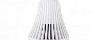
When designing LED lamps, great importance is given to their appearance, which has a huge impact on the shape of the heat sink. For example, the thermal energy dissipation system of an LED lamp should not go beyond the standard pear-shaped shape. This fact forces developers to resort to various tricks: using printed circuit boards with an aluminum base, connecting them to the radiator housing using hot-melt adhesive.
The "covered area" principle and its verification
It is obvious that not all folds, depressions and undercuts of the developed surface of the radiator are equally effective in dissipating thermal power into the environment. The principle of “covered area” is used in the estimated calculation of radiator efficiency and requires that only the “covered area” be taken as the effective radiator surface - the area of an elastic film that can be mentally wrapped around the radiator (Fig. 3). The rest of the surface is not taken into account.
Rice. 3. The principle of “covered area” is used in the evaluation calculation of a radiator and requires that the effective radiator surface be taken as the area of an elastic film that can be mentally wrapped around the radiator
To test the principle, we used an 80 × 150 × 35 mm aluminum radiator with eight fins and a similar one in which six internal fins were sawn off (Fig. 4). These radiators have different weights and numbers of fins, but the same covered area. × light modules with seven Cree XPG diodes are glued onto the radiators. The total power of the module was regulated and amounted to 23 W, so that at room temperature +25 ° C the radiator temperature was set to +55 ° C. The thermal resistance of a radiator is traditionally calculated as the ratio of the temperature difference between the radiator and the environment to the power dissipation. In this case, for the convenience of calculations and clarity of results, the total power consumption of the lamp is taken as the dissipated power (table).
Rice. 4. Cutting off six of the eight radiator fins had little effect on its heat dissipation ability.
Table. Changes in radiator characteristics when cutting six out of eight fins
| Parameter | Radiator with eight fins | Radiator with two fins |
| Weight, g | 411 | 239 |
| Total area, cm2 | 1010 | 488 |
| Covered area, cm2 | 401 | 401 |
| Steady-state temperature at Ta = +25 °C and P = 23 W, °C | 55 | 62 |
| Thermal resistance, K/W | 1,3 | 1,6 |
As a result of sawing off six ribs, the temperature increased by 7 °C. Let's evaluate the impact of this temperature increase on the main parameters of the lamp, using temperature dependencies from Cree technical documentation. As a result of sawing off six of the eight ribs:
- the total area decreased by 2.1 times;
- weight decreased by 1.7 times;
- thermal resistance increased by 23%;
- temperature increased by 7 °C;
- luminous flux decreased by ~1.6%;
- efficiency decreased by ~0.9%.
If we evaluate the effect of sawing off the ribs using the diagram (Fig. 5), it is clear that the principle of the covered area is correct and productive. Fins that do not affect the size of the covered area of the radiator do not determine the efficiency of the lamp and must be cut off at the design stage.
Rice. 5. The result of sawing off six out of eight ribs: the total area decreased significantly, the efficiency of the lamp remained virtually unchanged
Raw material
Aluminum is most often used to make heat sinks these days. The thing is that this material is very convenient for such purposes, and at the same time quite cheap. But if the dimensions of the product matter, then it is unlikely that you will be able to find anything better than copper, since it has greater heat conductivity, which means the heat sink will be 2 times smaller in size.
But not only these two materials are suitable for making a cooling device? It makes sense to understand what other raw materials a heat sink can be made from and what their differences are.
Aluminum
Aluminum radiator
In terms of thermal conductivity, the average value ranges from 200 to 240 W/m*K, which is almost 3 times higher than the same parameter for brass and iron. It mainly depends on the presence and amount of impurities in aluminum. Of course, this is an easy-to-process metal, which is why it is so common, but still, provided that the device body is small and decent cooling is required, an aluminum radiator is inferior to copper.
Copper
The indicator of this metal is 2 times higher than the thermal conductivity of aluminum, second only to such a noble metal as silver, and amounts to 400 W/m*K. But despite the fact that copper cools so well, such radiators are quite rare. The thing is that it is quite expensive when compared with aluminum, and besides, it is difficult to machine and has a large mass.
Copper radiator
It turns out that if copper coolers are installed in an LED lamp, its price will increase, and this is unacceptable, because as a result, the company will become uncompetitive in a tough market.
Ceramics
The thermal conductivity parameter is close to the parameters of aluminum and amounts to 175–235 W/m*K. Ceramics are convenient because they themselves are dielectrics, which is important in electronic and electrical circuits.
And yet, with such thermal conductivity, it loses to another material that is very easy to handle.
Thermoplastic
Of course, the thermal conductivity parameters of thermoplastic are slightly lower than those of aluminum (from 5 to 40 W/m*K), but it has some advantages. In addition to its dielectric properties, it is also very light and low cost. Only when designing LED lamps more powerful than 10 watts, it clearly loses to aluminum and copper.
The role of edge orientation
The natural question is: does the orientation of the fins significantly affect the thermal resistance of the radiator? Perhaps it would be advisable to rotate the fins so that the air rises freely between them, creating natural draft? And in this case, we will get a significantly more efficient radiator, the weight and complexity of which will be justified?
By repeating a series of experiments on a different day and with different equipment, it was checked whether the temperature of the radiator and its thermal resistance would change while maintaining the number of fins, but changing the orientation (Fig. 6). In four possible positions, the maximum difference in thermal resistance was recorded on an eight-fin radiator between the positions “sideways fins are horizontal” and “sideways fins are vertical” and amounted to 20% in favor of vertical fins. With the optimal location of the ribs, natural traction is formed. There is less difference between other pairs of positions. This is probably due to the relatively high viscosity of the air and the resulting unimpressive thrust effect in the narrow space between the fins.
Rice. 6. The maximum difference in thermal resistance of the radiator for different fin orientations was only 20%
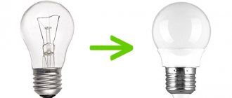
DIY LED radiator
It’s not difficult to make an aluminum radiator for 1, 3 or 10 W LEDs with your own hands. First, let's look at a simple design, the manufacture of which will take about half an hour and a round plate 1-3 mm thick. Along the circumference, cuts are made to the center every 5 mm, and the resulting sectors are slightly bent so that the finished structure resembles an impeller. To attach the radiator to the body, holes are made in several sectors. It's a little more difficult to make a homemade heatsink for a 10-watt LED. To do this you need 1 meter of aluminum strip 20 mm wide and 2 mm thick. First, the strip is cut with a hacksaw into 8 equal parts, which are then stacked, drilled through and tightened with a bolt and nut. One of the side faces is polished for mounting the LED matrix. Using a chisel, the strips are bent in different directions. Holes are drilled in the places where the LED module is attached. Hot melt adhesive is applied to the sanded surface, a matrix is applied on top, fixing it with self-tapping screws.
Inefficiency of large radiators
Is a huge radiator effective - with a obviously larger effective area than the required 20 cm2 per 1 W of lamp power? As practice shows, a significant increase in the radiator area beyond the minimum required has a very small effect on reducing the temperature of the board. Such a radiator copes with the task of heat removal, but its efficiency per kilogram of weight and ruble cost is low.
Rice. 7. Small radiators are effective per unit area, since the entire surface is used equally effectively
The reason for the ineffectiveness of the additional area is visible if we compare the thermograms of radiators with 18 cm2 of covered area per 1 W of power (Fig. 7) and an aluminum plate 300 × 300 × 1.5 mm with the same LED module (Fig. 8), which corresponds to 78 cm2 per 1 W of power.
Rice. 8. A significant increase in the radiator area almost does not lead to a decrease in the temperature of the board. Areas of the radiator area farthest from the heat generator do not participate in heat transfer
A fourfold increase in the covered area practically did not lead to a decrease in the temperature of the board due to the resulting temperature heterogeneity and the inefficiency of the extreme sections of the radiator area.
But even with a uniform distribution of power sources over the radiator, an increase in the radiator area leads to an exponential decrease in the difference between the temperature of the board and the ambient temperature. That is, to a strong decrease in temperature with an increase in small areas and a slight decrease with an increase in large areas. Increasing the radiator area above 30 cm2/1 W is irrational, and above 100 cm2/1 W is useless [1].
Cooling element area
There are two ways to calculate the area of the cooling element for an LED lamp - design and calibration.
The essence of the design is to determine the geometric dimensions of the cooled device, and the verification method is action from the reverse point, i.e., knowing the capabilities of the radiator based on its dimensions, you need to calculate how much heat transfer it will be capable of.
Of course, you need to decide which option is most acceptable separately in each specific case, based on the available data, but with any choice you need to understand that you need to solve an exact mathematical problem with formulas and many unknowns. In addition, in addition to reference literature, you will need graph data with the necessary formulas inserted into them, as well as taking into account not only the size and orientation of the grating that the heat sink has, but also external influences.
It also makes sense to take into account the country of origin of the LEDs, since the Chinese are often “pleased” by the discrepancy between the stated characteristics and the actual ones.
We calculate the radiator area
Please note that to correctly calculate the radiator area, the parameters of the useful dissipation area, and not the surface area, are taken into account. When calculating the usable area (S), the sum of the areas of the ribs and the substrate in square meters is included
It should be taken into account that each rib has two outlet surfaces. In this case, S of a rectangular heat sink S - 1 cm2 is - 2 cm2
When calculating the usable area (S), the sum of the areas of the ribs and the substrate in square meters is included. It should be taken into account that each rib has two outlet surfaces. In this case, S of a rectangular heat sink S - 1 cm2 is - 2 cm2.
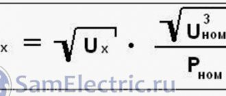
As a result of the experiments, a formula was derived for calculating the required heat sink area:
S = (22 – (M x 1.5)) x W, in which
S – radiator heat sink area; W – power supplied (W); M – LED power. For plate radiators made of aluminum, the following approximate data calculated by experts from Taiwan can be used:
- 1 W: 10 ÷ 15 cm2;
- 3 W: 30 ÷ 50 cm2;
- 10 W: approximately 1000 cm2;
- 60 W: 7000 73000 cm2.
Since the range of the indicated data has a wide range and they were determined in conditions for the climate of a southern country, the values are not absolutely accurate and are suitable for preliminary calculations.
More detailed information on calculating the radiator area can be obtained by watching the video.
DIY: Water Cooled Powerful LED
- Jurei-678
- October 6, 2016
- Homemade productsLight
We have a new addition to the section of useful homemade crafts: a powerful DIY water-cooled LED. Hi all! Sometimes you want to build a powerful LED lamp, but there is no suitable radiator or they are expensive and bulky.
Today I will show you how to cool a powerful 10-30 watt LED with a three by three centimeter radiator. We take the radiator and glue the LED onto it; as soon as the glue has dried, we apply colorless silicone to the LED and glue a piece of glass or lens onto it.
We also seal the negative and positive terminals with silicone; when the silicone dries, we lower the structure into a glass of water and check the water resistance between the conductors with an ohmmeter - it should be very high. We lower the LED into a 200 gram jar of water or oil, make a hole in the lid and turn on the power. After an hour of operating the lamp at 1000 mA, the water temperature rose from 19 to 21 degrees. An LED with a radiator can be glued directly to the bottom of the can, and an E 14 or E 27 socket can be attached on top - you can screw it into the chandelier by first converting the power supply to 12 volts. With such cooling, the LED does not blind as much as without water! Very pleasing to the eyes. If you add aromatic liquid to the oil, it will smell pleasant when illuminated.
Author of the article “Do it yourself: powerful water-cooled LED” Jurei-678
LED lamps with flexible copper busbar.
Finally, I got a chance to review LED lamps with natural air cooling, which use a copper braided busbar as a radiator. I have long been interested in how this cooling method would perform. For those who open this review just to write something about the cut-off line, I will say right away that this model does not have a cut-off line.
The lamps are supplied in a silver cardboard box, the contents are as follows:
1. Instructions with pictures. 2. Two lamps 3. Two drivers 4. Two O-rings
The purpose of the O-rings is not entirely clear to me; there is not a word about them in the instructions; I assume that they should be installed on a flexible busbar, at the point where it exits the lamp.
Instructions
Consider a lamp. It is made in an aluminum case with a removable adapter for the H4 base. The adapter is metal and quite massive, I hope this will play a role in improving heat dissipation. When installed, the adapter is pressed thanks to the silicone sealing ring. However, there is a minus here: the position of the lamp in the adapter is not fixed; usually in such cases there is a locking screw, but in this case there is none. Therefore, after installing the lamp in the headlight, you should turn it at the desired angle; usually this angle can be determined by the cut-off pattern in the low beam.
As for low and high beams, there is quite an interesting story. I thought that they had stopped doing this, but it turned out, no, they didn’t stop. So, despite the fact that this lamp uses Philips Z ES LEDs, you can’t expect a good cut-off line. I have already tested lamps with such LEDs and their cut-off boundaries were very good, I’m not saying ideal, like halogen, but very close to them. So, the lamp has 6 LEDs, three of which, located on one side of the lamp, are responsible for low beam, and with high beam all six LEDs turn on.
The dimensions of the LEDs, although they repeat the dimensions of the spiral of a halogen lamp, are located where the high beam spiral is located in a halogen lamp. When I was choosing lamps for review, I saw that the lamps did not have a curtain, I thought that for simplicity, lamps in the H7 base were shown, because there cannot be an H4 lamp without a curtain (as it turned out, it can).
On the side of the lamp we see the inscription PHILIPS 1711. And next to it is the “China Export” icon.
And the main, maybe even the only reason why I chose this lamp is the radiator. Made from a flexible copper busbar, for a very long time I wanted to find out how effective such radiators are. There are three strands here; to improve heat dissipation, it is recommended to flatten them into circles; I would also recommend stretching the braid as high as possible. This will increase the surface area and improve heat dissipation.
There is also a wire coming out of the back of the case that connects to the remote driver. The connection occurs using a sealed connector. The connector has an O-ring and is tightened using a clamp that is screwed on top.
Let's look into the driver. But again there’s nothing to see here; the driver inside is filled with compound.
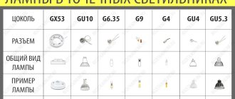
The lamps are available in 13 types of bases: 9012, D1S, D2S, H4, H7, H8, H9, H11, H1, H13, H3, 9004/HB1, 9005/HB3, some of which can be seen in the following picture.
Let's look at the declared characteristics of the lamps:
LED type:
Philips Z ES
Power:
55 W
Luminous flux:
6000 lm
Operating temperature:
-40 +80 °C
Supply voltage:
DC 9-32 V
Protection class:
IP68
Color temperature:
6000 K
Service life:
up to 32000 hours
Let's immediately look at the consumption of these lamps, which I will measure in the voltage range from 6 to 32 V. A little about taking parameters: first I warm up the lamp for about 15 minutes, then I measure the dependence of the current consumption on the applied voltage and write the results in a table.
I built a graph using the table. We see that at 14 V the lamp consumes 11.2 W on low beam and 21.7 W on high beam.
Then I warmed up the lamp in a small cardboard box as usual. This time I warmed up the lamp for 2 hours on low beam and 2 on high beam. In low beam, the LED heated up to 106.4 °C, the driver to 41.7 °C, and the tire temperature averaged about 45.5 °C. Since the bus, like the driver, has an unknown reflectance, I applied small strokes of strokes to the bus and driver. These points are clearly visible on the thermograms. For accuracy, I installed a thermocouple in the braided tire and took a couple of measurements. The values obtained from measurements with a thermal imager and thermocouple practically coincided. The wires sticking out of the tire can be seen in one of the thermal diagrams.
In high beam, the LEDs heated up to 135.6 °C, the driver surface temperature was 63.8 °C, and the braid temperature was about 60 °C. Yes, 135 degrees is a lot, but of all the naturally cooled lamps I have previously tested, this is currently the best option. In one model I previously tested, the LEDs heated up to 139 C°, but this is with a lamp consumption of only 13 W; if the lamp has a consumption of about 20 W, the temperature of the LEDs usually exceeds 160 C°. Sometimes the temperature of the LEDs can be slightly reduced by replacing the thermal paste at the junction of the radiator with the lamp body, but this does not always help, twice it helped reduce the temperature of the LEDs by 10 C° and once it turned out to be almost useless, apparently a good thermal paste was used, which it was also applied correctly. We can definitely say that copper braid is one of the best types of radiators for automobile LED lamps with natural air cooling.
If the braid is fluffed more strongly, then due to the increase in surface area, the temperature of the LEDs will drop by about another one and a half degrees. And if, on the contrary, the braid is compressed as much as possible, then the temperature of the LEDs will increase by about 1°C.
The dimensions of the lamp, excluding the protruding braid, practically do not exceed the dimensions of a standard incandescent lamp. This will allow it to be easily installed in most headlights.
As I already said, there is no cut-off line here, but to complete the picture, let’s still compare it with the stg of a standard halogen lamp. In the following photos there is an LED lamp on the left, a halogen lamp on the right.
Now the same for high beams.
And to get a better idea of the brightness of the lamp, let's direct the light into the distance, first the near one. On the left is an LED lamp, on the right is a halogen lamp.
Now the distant one. On the left is an LED lamp, first halogen.
Conclusion.
Although the temperature of the LEDs is quite high, it is worth noting that the flexible copper bus copes with its task better than hotel types of radiators with natural air cooling. We see that these lamps do not have a curtain over the LEDs, and without this curtain the H4 lamp type will not be able to form a normal cut-off line. Typically, the diodes used here make it possible to obtain very good cut-off boundaries. Perhaps if the lamps were in an H7 socket or some other, then the stg would be much better.
That's all I have. I hope the review was interesting.
The product was provided for writing a review by the store. The review was published in accordance with clause 18 of the Site Rules.