Design features
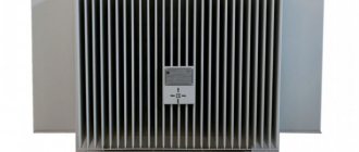
From a technical point of view, the AIR electric motor is one of the types of asynchronous electric machines. This variety first came into use back in 1973 and replaced the 4A and AM brands thanks to a new international standard that established its parameters and technical features. A structural example of asynchronous electric motors is shown in the figure below:
Rice. 1. Design of the AIR electric motor
As you can see, the AIR engine consists of the following main structural elements:
- Housing - made of cast iron or lightweight alloys, designed to hold internal parts and fasten to the working surface.
- Stator magnetic circuit - used as a medium for conducting magnetic flux from the windings to the rotor.
- Stator windings are made of copper conductors with varnish insulation, as a rule, they have an additional layer. Designed for the flow of alternating current, which generates electromagnetic waves. The winding wires are laid in the stator grooves.
- The rotor is phase or short-circuited; the phase rotor consists of a metal shaft on which there is a squirrel cage and windings placed in its grooves. The squirrel-cage rotor is a monolithic block made of ferromagnetic material. The rotor is designed to rotate inside the electric motor due to the influence of electromagnetic forces.
- Borna - the terminal box is designed to connect the electrical power cable, allowing you to change the connection diagram of the windings.
Connection diagram
General industrial three-phase electric motor is a type of electric motor product that unites dozens of brands from ADM to AIR; products of all series are distinguished by reliability, reasonable price, and high-quality performance characteristics. General industrial electric motors are understood as asynchronous motors included in the drive package, operating on alternating current not only indoors , but also under canopies and in open areas. The AIR engine (100, 112, 132, 160) is interchangeable with such series as:
- A,
- 4A,
- AD, etc.
Explanation of markings
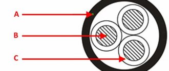
Rice.
2. Example of designation on a nameplate Like any device, AIR electric motors are produced with different operating parameters, which are displayed both in the passport data and in its markings.
Let's consider the decoding of one of the units of the AIR series:
AIR 80 A 4 U2 IM2081 IP54
Here the marking of the electric motor indicates the following data:
- AIR - indicates the brand (A - asynchronous, IR - manufactured according to the Interelectro standard);
- 80 – axis height value, expressed in millimeters; AIR electric motors are manufactured with dimensions from 56 to 355 mm;
- A – shaft length, in this type of electric machine the designation is done in letters in order from smallest to largest;
- 4 – number of poles, which determines the possible rotation speed;
- U2 – climatic version, which determines the permissible parameters of the engine type;
- IM2081 – installation method, which determines the method of installing the mechanism drive in relation to the working surface;
- IP54 – degree of dust and moisture protection of the device.
Electric motors AIR, A, 4A, 5AI, AD
| Dimensions | Number of poles | dimensions | Installation and connecting dimensions, mm | ||||||||||||||
| L | H | A | A1 | b | d | d1 | d2 | d3 | d4 | d5 | h | H1 | l | l1 | t | ||
| 50 | 2, 4 | 178 | 130 | 63 | 80 | 3 | 9 | 6 | 7 | 80 | 100 | 120 | 6 | 50 | 20 | 32 | 10 |
| 56 | 2, 4 | 197 | 145 | 71 | 90 | 4 | 11 | 6 | 10 | 95 | 115 | 140 | 7 | 56 | 23 | 36 | 13 |
| 63 | 2, 4, 6 | 226 | 170 | 80 | 100 | 5 | 14 | 7 | 10 | 110 | 130 | 160 | 7 | 63 | 30 | 40 | 16 |
| 71 | 2, 4, 6, 8 | 270 | 185 | 90 | 112 | 6 | 19 | 7 | 12 | 130 | 165 | 200 | 8 | 71 | 40 | 45 | 22 |
| 80A | 2, 4, 6, 8 | 297 | 205 | 100 | 125 | 6 | 22 | 10 | 12 | 130 | 165 | 200 | 9 | 80 | 50 | 50 | 25 |
| 80V | 2, 4, 6 | 321 | 205 | 100 | 125 | 6 | 22 | 10 | 12 | 130 | 165 | 200 | 10 | 80 | 50 | 50 | 25 |
| 80V | 8 | 297 | 205 | 100 | 125 | 6 | 22 | 10 | 12 | 130 | 165 | 200 | 10 | 80 | 50 | 50 | 25 |
| 90L | 2, 4, 6, 8 | 337 | 225 | 125 | 140 | 8 | 24 | 10 | 15 | 180 | 215 | 250 | 10 | 90 | 50 | 56 | 27 |
| 100S | 2, 4 | 390 | 242 | 112 | 160 | 8 | 28 | 12 | 15 | 180 | 215 | 250 | 12 | 100 | 60 | 63 | 31 |
| 100L | 2, 4, 6, 8 | 390 | 242 | 140 | 160 | 8 | 28 | 12 | 15 | 180 | 215 | 250 | 12 | 100 | 60 | 63 | 31 |
| 112 | 2, 4, 6, 8 | 443 | 275 | 140 | 190 | 10 | 32 | 12 | 15 | 230 | 265 | 300 | 14 | 112 | 80 | 70 | 35 |
| 132S | 4, 6 | 483 | 295 | 140 | 216 | 10 | 38 | 12 | 19 | 250 | 300 | 350 | 16 | 132 | 80 | 89 | 41 |
| 132S | 8 | 546 | 360 | 140 | 216 | 10 | 38 | 12 | 19 | 250 | 300 | 350 | 17 | 132 | 80 | 89 | 41 |
| 132M | 2, 4, 6 | 483 | 295 | 178 | 216 | 10 | 38 | 12 | 19 | 250 | 300 | 350 | 16 | 132 | 80 | 89 | 41 |
| 132M | 8 | 546 | 360 | 178 | 216 | 10 | 38 | 12 | 19 | 250 | 300 | 350 | 17 | 132 | 80 | 89 | 41 |
| 160S | 2 | 670 | 404 | 178 | 254 | 12 | 42 | 15 | 19 | 250 | 300 | 350 | 20 | 160 | 110 | 108 | 45 |
| 4, 6, 8 | 670 | 404 | 178 | 254 | 14 | 48 | 15 | 19 | 250 | 300 | 350 | 20 | 160 | 110 | 108 | 52 | |
| 160M | 2 | 700 | 404 | 210 | 254 | 12 | 42 | 15 | 19 | 250 | 300 | 350 | 20 | 160 | 110 | 108 | 45 |
| 4, 6, 8 | 700 | 404 | 210 | 254 | 14 | 48 | 15 | 19 | 250 | 300 | 350 | 20 | 160 | 110 | 108 | 52 | |
| 180S | 2 | 710 | 465 | 203 | 279 | 14 | 48 | 15 | 19 | 300 | 350 | 400 | 21 | 180 | 110 | 121 | 52 |
| 4 | 710 | 465 | 203 | 279 | 16 | 55 | 15 | 19 | 300 | 350 | 400 | 21 | 180 | 110 | 121 | 59 | |
| 180M | 2 | 710 | 465 | 241 | 279 | 14 | 48 | 15 | 19 | 300 | 350 | 400 | 21 | 180 | 110 | 121 | 52 |
| 4, 6, 8 | 710 | 465 | 241 | 279 | 16 | 55 | 15 | 19 | 300 | 350 | 400 | 21 | 180 | 110 | 121 | 59 | |
| 200M | 2 | 735 | 495 | 267 | 318 | 16 | 55 | 19 | 19 | 350 | 400 | 450 | 25 | 200 | 110 | 133 | 59 |
| 4, 6, 8 | 765 | 495 | 267 | 318 | 18 | 60 | 19 | 19 | 350 | 400 | 450 | 25 | 200 | 140 | 133 | 64 | |
| 200L | 2 | 781 | 495 | 305 | 318 | 16 | 55 | 19 | 19 | 350 | 400 | 450 | 25 | 200 | 110 | 133 | 59 |
| 4, 6, 8 | 811 | 495 | 305 | 318 | 18 | 60 | 19 | 19 | 350 | 400 | 450 | 25 | 200 | 140 | 133 | 64 | |
| 225M | 2 | 835 | 540 | 311 | 356 | 16 | 55 | 19 | 19 | 450 | 500 | 550 | 30 | 225 | 110 | 149 | 59 |
| 4, 6, 8 | 865 | 540 | 311 | 356 | 18 | 65 | 19 | 19 | 450 | 500 | 550 | 30 | 225 | 140 | 149 | 69 | |
| 250S | 2 | 935 | 630 | 311 | 406 | 18 | 65 | 24 | 19 | 450 | 500 | 550 | 30 | 250 | 140 | 168 | 69 |
| 4, 6, 8 | 935 | 630 | 311 | 406 | 20 | 75 | 24 | 19 | 450 | 500 | 550 | 30 | 250 | 140 | 168 | 80 | |
| 250M | 2 | 965 | 630 | 349 | 406 | 18 | 65 | 24 | 19 | 450 | 500 | 550 | 30 | 250 | 140 | 168 | 69 |
| 4, 6 | 965 | 630 | 349 | 406 | 20 | 75 | 24 | 19 | 450 | 500 | 550 | 30 | 250 | 140 | 168 | 80 | |
| 8 | 935 | 630 | 349 | 406 | 20 | 75 | 24 | 19 | 450 | 500 | 550 | 30 | 250 | 140 | 168 | 80 | |
| 280S | 2 | 1080 | 660 | 368 | 457 | 20 | 70 | 24 | 24 | 550 | 600 | 660 | 30 | 280 | 140 | 190 | 75 |
| 4, 6, 8, 10 | 1110 | 660 | 368 | 457 | 22 | 80 | 24 | 24 | 550 | 600 | 660 | 30 | 280 | 170 | 190 | 85 | |
| 280M | 2 | 1080 | 660 | 419 | 457 | 20 | 70 | 24 | 24 | 550 | 600 | 660 | 30 | 280 | 140 | 190 | 75 |
| 4, 6, 8, 10 | 1110 | 660 | 419 | 457 | 22 | 80 | 24 | 24 | 550 | 600 | 660 | 30 | 280 | 170 | 190 | 85 | |
| 315S | 2 | 1160 | 815 | 406 | 508 | 20 | 75 | 28 | 24 | 550 | 600 | 660 | 40 | 315 | 140 | 216 | 80 |
| 4 | 1290 | 815 | 406 | 508 | 25 | 90 | 28 | 24 | 550 | 600 | 660 | 40 | 315 | 170 | 216 | 95 | |
| 6, 8, 10, 12 | 1190 | 815 | 406 | 508 | 25 | 90 | 28 | 24 | 550 | 600 | 660 | 40 | 315 | 170 | 216 | 95 | |
| 315M | 2 | 1260 | 815 | 457 | 508 | 20 | 75 | 28 | 24 | 550 | 600 | 660 | 40 | 315 | 140 | 216 | 80 |
| 4 | 1290 | 815 | 457 | 508 | 25 | 90 | 28 | 24 | 550 | 600 | 660 | 40 | 315 | 170 | 216 | 95 | |
| 6, 8, 10, 12 | 1190 | 815 | 457 | 508 | 25 | 90 | 28 | 24 | 550 | 600 | 660 | 40 | 315 | 170 | 216 | 95 | |
| 355S | 2 | 1565 | 1010 | 500 | 610 | 22 | 85 | 28 | 24 | 680 | 740 | 800 | 52 | 355 | 170 | 254 | 90 |
| 4, 6, 8, 10, 12 | 1570 | 1010 | 500 | 610 | 28 | 100 | 28 | 24 | 680 | 740 | 800 | 52 | 355 | 210 | 254 | 106 | |
| 355M | 2 | 1565 | 1010 | 560 | 610 | 22 | 85 | 28 | 24 | 680 | 740 | 800 | 52 | 355 | 170 | 254 | 90 |
| 4, 6, 8, 10, 12 | 1570 | 1010 | 560 | 610 | 28 | 100 | 28 | 24 | 680 | 740 | 800 | 52 | 355 | 210 | 254 | 106 | |
Note: Overall and installation dimensions may vary from manufacturer to manufacturer. More precisely, the above dimensions for each manufacturer can be found in the corresponding product catalog.
Specifications
The installation and subsequent operation of the AIR electric motor must be adjusted to the mechanical load connected to its shaft, connection and operating conditions. The technical characteristics of the electric machine are selected in accordance with the above parameters. The engine characteristics are also indicated in the passport or on the nameplate.
Key technical data include:
- Power – determines the amount of electricity processed; for AIR electric motors this parameter ranges from 0.12 to 315 kW.
- The supply voltage depends to a certain extent on the winding connection diagram. AIR electric motors can be connected either in star or triangle, so the voltage is indicated for both methods - 220/380 or 380/660V.
- Rotation speed is the number of revolutions per unit of time; for the AIR brand it can range from 750 rpm to 3000 rpm.
- Efficiency - determines the ratio between energy expended and work done.
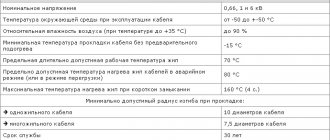
- The permissible temperature range is usually from – 40 to + 45ºС.
- Type of installation - in total there are three methods for the AIR electric motor: IM1081 - on the frame (horizontally), IM2081 both on the frame and on the flange (both horizontally and vertically), IM3081 only on the flange (vertically). An example of basic design options is shown in the figure below:
Rice. 3. Method of mounting the AIR electric motor
- Electrical and magnetic losses are determined by the open circuit voltage and short-circuit current.
- Geometric dimensions - indicate the main dimensions and distances from the elements of the electric machine to the nearest parts with which the motors are used.
- The degree of dust and moisture protection is indicated by two Latin letters IP and a pair of numbers, one of which determines resistance to dust, and the second to moisture.
The general industrial purpose of some of them involves technical features, which are indicated by the corresponding letters with which the engines are produced:
- B – ensures operation in high temperature conditions;
- B – built-in electrical machines;
- C – with increased sliding parameter;
- E – with the function of forced rotor braking.
- E2 – with manual braking control.
- ZE is a three-phase device for connecting to a single-phase network.
- F – for pumping units.
- RZ - in motor-gear devices.
- Sh – general industrial electric motors for the clothing industry.
- P – with high precision mounting characteristics.
- F – oil-resistant version.
- A – used in nuclear power plants.
- X2 – increased chemical resistance.
The best manufacturers
In view of the constant filling of the market with electric machines of the most varied quality, the question is quite acute when purchasing an AIR electric motor. By purchasing such a unit, the user expects to receive in return long-term, uninterrupted operation, since asynchronous machines are much more reliable and relatively rarely fail.
However, in practice, various counterfeits often surface, usually cheap Chinese products, and sometimes they try to pass them off as newly minted domestic manufacturers of engines in the main industrial sector. Therefore, to buy an AIR electric motor, you should choose proven brands that meet the standards, and their units can withstand the declared operating modes.
The list of the best manufacturers of electric motors of the AIR series is given in the table below:
Table: list of the best manufacturers of AIR electric motors
| Manufacturer name | Short description |
| SLEMZ (Kharkov electromechanical plant) | It produces AIR electric motors with power from 0.75 to 75 kW of various designs. |
| "Ukrelectromash" (Kharkiv electrical plant) | Produces a low-power line of electric machines of the AIR brand |
| "ELDIN" (Yaroslavl plant) | One of the largest manufacturers of asynchronous machines in Russia |
| Sibelektromotor (Tomsk plant) | Mostly focused on the production of crane electric motors. |
| "Electrodvigatel" (Mogilev plant) | Focused on a wide range of drive products |
| "Polesieelectromash" (Luninets plant) | They not only manufacture, but also repair AIR electric motors |
Nuances of operation
In the case of installation and subsequent use of basic AIR electric motors, it is important to observe and take into account some of the nuances specified by the manufacturer, namely:
- The electric motor must be connected through a protection system against short circuit currents, overheating, phase failure, overloads, etc.
- When performing installation work or connecting the AIR electric motor, it is important to ensure an air flow for cooling; the casing itself must be moved away from obstacles by at least 20mm.
- In case of couplings, the shaft of the AIR electric motor is aligned coaxially with the load.
- Regardless of the connection method, subsequent balancing of the load on the shaft is required.
- It is important to consider that the rotor is balanced without keys.
Three-phase motors AIR series
Dimensions of general industrial motors
Table 1
Dimensions of general industrial motors
| Dimensions, mm | engine's type | ||||||||||||||||||||||||||
| AIR56 | AIR63 | AIR71 | AIR80A | AIR 80V,C | AIR90 | AIR 100S | AIR 100L | AIR 112 | AIR 132S | AIR 132M | AIR160S | AIR160M | AIR180S | AIR180M | |||||||||||||
| 2 | 4,6,8, 4/2, 6/4/2,8/4/2 | 2 | 4,6,8, 4/2, 6/4/2,8/4/2 | 2 | 4,6,8 | 2 | 4,6,8 | ||||||||||||||||||||
| L1 | 23 | 30 | 40 | 50 | 50 | 50 | 60 | 60 | 80 | 80 | 80 | 110 | |||||||||||||||
| L10 | 71 | 80 | 90 | 100 | 100 | 125 | 112 | 140 | 140 | 140 | 178 | 178 | 210 | 203 | 241 | ||||||||||||
| L11 | 87 | 97 | 110 | 125 | 125 | 155 | 147 | 175 | 174 | 180 | 218 | 232 | 264 | 248 | 286 | ||||||||||||
| L17 | 5,8 | 7,0 | 7,0 | 10 ,0 | 10,0 | 10,0 | 12,0 | 12,0 | 12,0 | 12,0 | 12,0 | 15 | |||||||||||||||
| L20 | IM2081 IM3041 | 3,0 | 3,5 | 3,5 | 3,5 | 3,5 | 4,0 | 4,0 | 4,0 | 4,0 | 5,0 | 5,0 | 5 | ||||||||||||||
| IM2181 IM3641 | 2,5 | 2,5 | 3,0 | 2,5 | 3,0 | 3,0 | 3,5 | 3,0 | 3,5 | 3,5 | 3,0 | 3,5 | 3,5 | 3,5 | 3,5 | 3,5 | — | ||||||||||
| L21 | 10 | 10 | 10 | 10 | 10 | 12 | 14 | 14 | 15 | 19 | 19 | 13 | 15 | ||||||||||||||
| L30 | 218 | 237 | 272,5 332* | 296,5 368* | 320,5 392* | 337 401* | 360 430* | 391 460* | 433 | 463 | 501 | 680 | 710 | 645 | 685 | ||||||||||||
| L31 | 36 | 40 | 45 | 50 | 50 | 56 | 63 | 63 | 70 | 89 | 89 | 108 | 121 | ||||||||||||||
| L33 | 234,0 | 263,0 | 316,5 | 350,0 | 374,0 | 390,0 | 424,0 | 455,0 | 516,0 | 546,0 | 584,0 | 785 | 815 | 760 | 800 | ||||||||||||
| L39 | 0 | 0 | 0 | 0 | 0 | 0 | 0 | 0 | 0 | 0 | 0 | 0 | |||||||||||||||
| b | 23 | 25 | 28 | 30 | 30 | 33 | 43 | 43 | 47,5 | 46,5 | 46,5 | 50 | 50 | ||||||||||||||
| b1 | 4 | 5 | 6 | 6 | 6 | 8 | 8 | 8 | 10 | 10 | 10 | 12 | 14 | 12 | 14 | 14 | 16 | 14 | 16 | ||||||||
| b2 | 12 | 14 | |||||||||||||||||||||||||
| b10 | 90 | 100 | 112 | 125 | 125 | 140 | 160 | 160 | 190 | 216 | 216 | 254 | 279 | ||||||||||||||
| b11 | 107 | 119 | 137 | 150 | 150 | 170 | 200 | 200 | 225 | 256 | 256 | 307 | 332 | ||||||||||||||
| b16 | 8,8 | 10 | 10 | 12 | 12 | 12 | 16 | 16 | 16 | 16 | 16 | 20 | |||||||||||||||
| b30 | 129 | 142 | 160 | 180 | 180 | 198 | 226 | 226 | 250 | 290 | 290 | 350 | 375 | ||||||||||||||
| b31** | 90 | 90 | 115 | — | 115 | — | 120 | — | — | — | — | — | — | — | — | ||||||||||||
| h | 56 | 63 | 71 | 80 | 80 | 90 | 100 | 100 | 112 | 132 | 132 | 160 | 180 | ||||||||||||||
| h1 | 4 | 5 | 6 | 6 | 6 | 7 | 7 | 7 | 8 | 8 | 8 | 8 | 9 | 8 | 9 | 9 | 10 | 9 | 10 | ||||||||
| h2 | 8 | 9 | |||||||||||||||||||||||||
| h5 | 12,5 | 16,0 | 21,5 | 24,5 | 24,5 | 27,0 | 31,0 | 31,0 | 35,0 | 41,0 | 41,0 | 45 | 51,5 | 45 | 51,5 | 51,5 | 59 | 51,5 | 59 | ||||||||
| h6 | 45 | 51,5 | |||||||||||||||||||||||||
| h10 | 7 | 8 | 8 | 9 | 9 | 10 | 12 | 12 | 14 | 16 | 16 | 20 | |||||||||||||||
| h31 | 148 | 161 | 188 225* | 204,5 241,5* | 204,5 241,5* | 230,0 267* | 246,5 288* | 246,5 288* | 276 | 316 | 316 | 405 | 445 | ||||||||||||||
| d1 | 11 | 14 | 19 | 22 | 22 | 24 | 28 | 28 | 32 | 38 | 38 | 42 | 48 | 42 | 48 | 48 | 55 | 48 | 55 | ||||||||
| d2 | 42 | 48 | |||||||||||||||||||||||||
| d20 | IM2081 IM3041 | FF | 115 | 130 | 165 | 165 | 165 | 215 | 215 | 215 | 265 | 300 | 300 | 300 | 350 | ||||||||||||
| IM2181 IM3641 | F.T. | 65 | 85 | 75 | 100 | 85 | 115 | 100 | 130 | 100 | 130 | 130 | 115 | 130 | 130 | 165 | 165 | 165 | — | — | |||||||
| d22 | IM2081 IM3041 | 10 | 10 | 12 | 12 | 12 | 15 | 15 | 15 | 15 | 19 | 19 | 19 | ||||||||||||||
| IM2181 IM3641 | M5 | M6 | M5 | M6 | M6 | M8 | M6 | M8 | M6 | M8 | M8 | M8 | M8 | M10 | M10 | M10 | — | ||||||||||
| d24 | IM2081 IM3041 | 140 | 160 | 200 | 200 | 200 | 250 | 250 | 250 | 300 | 350 | 350 | 350 | 400 | |||||||||||||
| IM2181 IM3641 | 80 | 99 | 90 | 110 | 105 | 140 | 120 | 160 | 120 | 160 | 160 | 140 | 160 | 160 | 211 | 200 | 200 | — | — | ||||||||
| d25 | IM2081 IM3041 | 95 | 110 | 130 | 130 | 130 | 180 | 180 | 180 | 230 | 250 | 250 | 250 | 300 | |||||||||||||
| IM2181 IM3641 | 50 | 70 | 60 | 80 | 70 | 95 | 80 | 110 | 80 | 110 | 110 | 95 | 110 | 110 | 130 | 130 | 130 | — | — | ||||||||
Notes:
*—dimensions for motors with built-in electromagnetic brake
** - only for single-phase motors with an attached capacitor
*** - for motors with energy efficiency class IE2, dimensions L30, L33 may differ upward
table 2
Electrical parameters and masses (for version IM1081) of motors with energy efficiency class IE1 (for P ≥ 0.75 kW)
| Type | Electrical parameters | |||||||||
| R, kW | Nom. rotation speed, rpm | Efficiency, % | cosϕ | In*, A | Iн/Iн | Mn/Mn | Mmax/Mn | M min/Mn | Weight, kg | |
| AIR56A2 | 0,18 | 2730 | 65,0 | 0,78 | 0,9/0,5 | 5,0 | 2,2 | 2,2 | 1,8 | 3,5 |
| AIR56V2 | 0,25 | 2700 | 66,0 | 0,79 | 1,2/0,7 | 5,0 | 2,2 | 2,2 | 1,8 | 3,8 |
| AIR56A4 | 0,12 | 1350 | 57,0 | 0,66 | 0,8/0,5 | 5,0 | 2,2 | 2,2 | 1,8 | 3,6 |
| AIR56V4 | 0,18 | 1350 | 60,0 | 0,68 | 1,2/0,7 | 5,0 | 2,2 | 2,2 | 1,8 | 4,2 |
| AIR6ZA2 | 0,37 | 2730 | 72,0 | 0,84 | 1,6/0,9 | 5,0 | 2,2 | 2,2 | 1,8 | 5,2 |
| AIR63V2 | 0,55 | 2730 | 75,0 | 0,81 | 2,4/1,4 | 5,0 | 2,2 | 2,2 | 1,8 | 6,1 |
| AIR63A4 | 0,25 | 1320 | 65,0 | 0,67 | 1,5/0,9 | 5,0 | 2,2 | 2,2 | 1,8 | 5,1 |
| AIR6ZV4 | 0,37 | 1320 | 68,0 | 0,70 | 2,0/1,2 | 5,0 | 2,2 | 2,2 | 1,8 | 6,0 |
| AIR6ZA6 | 0,18 | 860 | 63,0 | 0,68 | 1,1/0,6 | 4,0 | 2,2 | 2,2 | 1,6 | 4,8 |
| AIR6ZV6 | 0,25 | 860 | 59,0 | 0,62 | 1,8/1,0 | 4,0 | 2,2 | 2,2 | 1,6 | 5,6 |
| AIR71A2 | 0,75 | 2820 | 72,1 | 0,80 | 3,4/2,0 | 6,0 | 2,6 | 2,7 | 1,6 | 8,7 |
| AIR71V2 | 1,10 | 2810 | 75,0 | 0,80 | 4,8/2,8 | 6,0 | 2,2 | 2,4 | 1,6 | 9,5 |
| AIR71A4 | 0,55 | 1360 | 71,0 | 0,71 | 2,9/1,7 | 5,0 | 2,3 | 2,4 | 1,8 | 8,1 |
| AIR71V4 | 0,75 | 1350 | 72,1 | 0,75 | 3,6/2,1 | 5,0 | 2,5 | 2,6 | 2,4 | 9,4 |
| AIR71A6 | 0,37 | 900 | 65,0 | 0,63 | 2,4/1,4 | 4,5 | 2,1 | 2,2 | 1,6 | 8,6 |
| AIR71V6 | 0,55 | 920 | 69,0 | 0,68 | 3,1/1,8 | 4,5 | 1,9 | 2,2 | 1,6 | 9,9 |
| AIR71V8 | 0,25 | 690 | 58,0 | 0,60 | 1,9/1,1 | 4,0 | 1,7 | 1,9 | 1,4 | 9,9 |
| AIR80A2 | 1,50 | 2865 | 77,2 | 0,85 | 6,0/3,5 | 6,5 | 2,2 | 2,4 | 1,8 | 12,4 |
| AIR80V2 | 2,20 | 2860 | 79,7 | 0,87 | 8,3/4,8 | 6,4 | 2,1 | 2,6 | 1,8 | 15,0 |
| AIR80A4 | 1,10 | 1390 | 75,0 | 0,77 | 5,0/2,8 | 5,0 | 1,9 | 2,0 | 1,3 | 11,9 |
| AIR80V4 | 1,50 | 1390 | 77,2 | 0,80 | 6,4/3,7 | 5,3 | 2,2 | 2,4 | 1,7 | 13,8 |
| AIR80A6 | 0,75 | 920 | 70,0 | 0,71 | 3,9/2,3 | 4,0 | 2,1 | 2,2 | 1,6 | 11,6 |
| AIR80V6 | 1,10 | 925 | 72,9 | 0,71 | 5,4/3,1 | 4,5 | 2,2 | 2,3 | 1,8 | 15,3 |
| AIR80A8 | 0,37 | 670 | 58,0 | 0,59 | 2,8/1,6 | 3,5 | 2,0 | 2,3 | 1,4 | 12,8 |
| AIR80V8 | 0,55 | 670 | 58,0 | 0,60 | 4,1/2,4 | 3,5 | 2,0 | 2,1 | 1,4 | 14,8 |
| AIR90L2 | 3,00 | 2860 | 81,5 | 0,85 | 11,4/6,6 | 7,0 | 2,3 | 2,6 | 1,7 | 19,0 |
| AIR90L4 | 2,20 | 1420 | 79,7 | 0,79 | 9,2/5,3 | 6,0 | 2,0 | 2,4 | 2,0 | 18,1 |
| AIR90L6 | 1,50 | 940 | 75,2 | 0,70 | 7,4/4,3 | 5,0 | 2,0 | 2,3 | 1,9 | 19,0 |
| AIR90LA8 | 0,75 | 700 | 70,0 | 0,71 | 4,0/2,3 | 4,0 | 1,5 | 2,0 | 1,5 | 17,7 |
| AIR90LB8 | 1,10 | 710 | 74,0 | 0,72 | 5,4/3,1 | 4,5 | 1,5 | 2,2 | 1,5 | 20,5 |
| AIR100S2 | 4,00 | 2890 | 83,1 | 0,88 | 14,4/8,3 | 7,5 | 2,0 | 2,4 | 1,6 | 26,0 |
| AIR100L2 | 5,50 | 2850 | 84,7 | 0,88 | 19,4/11,2 | 7,5 | 2,1 | 2,4 | 1,6 | 31,5 |
| AIR100S4 | 3,00 | 1410 | 81,5 | 0,82 | 11,8/6,8 | 7,0 | 2,0 | 2,2 | 1,6 | 23,0 |
| AIR100L4 | 4,00 | 1410 | 83,1 | 0,84 | 15,0/8,7 | 7,0 | 2,1 | 2,4 | 1,6 | 29,2 |
| AIR100L6 | 2,20 | 945 | 77,7 | 0,74 | 10,1/5,8 | 6,0 | 1,9 | 2,2 | 1,6 | 27,0 |
| AIR100L8 | 1,50 | 700 | 76,5 | 0,70 | 7,4/4,2 | 3,7 | 1,6 | 2,0 | 1,5 | 24,0 |
| AIR112M2 | 7,50 | 2900 | 86,0 | 0,88 | 26,0/15,1 | 7,5 | 2,0 | 2,2 | 1,6 | 40,0 |
| AIR112M4 | 5,50 | 1430 | 84,7 | 0,86 | 19,8/11,5 | 7,0 | 2,0 | 2,5 | 1,6 | 38,5 |
| AIR112MA6 | 3,00 | 950 | 79,7 | 0,72 | 13,2/7,6 | 6,0 | 2,0 | 2,2 | 1,6 | 33,4 |
| AIR112MV6 | 4,00 | 950 | 81,4 | 0,81 | 15,8/9,2 | 6,0 | 2,0 | 2,2 | 1,6 | 38,8 |
| AIR112MA8 | 2,20 | 700 | 78,0 | 0,70 | 10,6/6,1 | 6,0 | 1,8 | 2,2 | 1,4 | 33,4 |
| AIR112MV8 | 3,00 | 700 | 80,0 | 0,70 | 14,1/8,2 | 6,0 | 1,8 | 2,0 | 1,4 | 39,0 |
| AIR132M2 | 11,00 | 2910 | 87,6 | 0,86 | 38,3/22,2 | 7,5 | 1,6 | 2,2 | 1,2 | 60,4 |
| AIR132S4 | 7,50 | 1440 | 86,0 | 0,83 | 27,6/16,0 | 7,5 | 2,0 | 2,5 | 1,6 | 53,5 |
| AIR1Z2M4 | 11,00 | 1450 | 87,6 | 0,83 | 39,3/23,0 | 7,5 | 2,4 | 2,9 | 2,2 | 66,3 |
| AIIP132S6 | 5,50 | 960 | 83,1 | 0,76 | 22,9/13,2 | 7,0 | 2,0 | 2,2 | 1,6 | 52,3 |
| AIR132M6 | 7,50 | 950 | 84,7 | 0,77 | 30,2/17,5 | 7,0 | 2,0 | 2,2 | 1,6 | 64,5 |
| AIR132S8 | 4,00 | 710 | 80,0 | 0,70 | 18,7/10,9 | 6,0 | 1,8 | 2,2 | 1,4 | 52,2 |
| AIR132M8 | 5,50 | 700 | 84,0 | 0,72 | 23,9/13,8 | 6,0 | 1,8 | 2,2 | 1,4 | 62,2 |
| AIIP160S2 | 15,00 | 2930 | 88,7 | 0,89 | 49,9/28,9 | 7,0 | 2,1 | 3,0 | 2,0 | 95,7 |
| AIR160M2 | 18,50 | 2930 | 89,3 | 0,89 | 61,1/35,4 | 7,0 | 2,2 | 3,0 | 2,0 | 107,1 |
| AIR160S4 | 15,00 | 1460 | 88,7 | 0,84 | 52,8/30,6 | 6,5 | 2,3 | 2,7 | 2,0 | 97,1 |
| AIR160M4 | 18,50 | 1460 | 89,3 | 0,86 | 63,2/36,6 | 6,5 | 2,3 | 2,7 | 2,0 | 103,9 |
| AIR160S6 | 11,00 | 970 | 86,4 | 0,81 | 40,7/23,6 | 6,5 | 1,9 | 2,6 | 1,7 | 98,3 |
| AIR160M6 | 15,00 | 970 | 87,7 | 0,82 | 54,7/31,7 | 6,5 | 2,0 | 2,6 | 1,7 | 113,9 |
| AIR160S8 | 7,50 | 720 | 87,0 | 0,72 | 31,8/18,4 | 5,5 | 1,7 | 2,3 | 1,5 | 86,9 |
| AIR160M8 | 11,00 | 720 | 88,0 | 0,73 | 45,5/26,4 | 5,5 | 1,7 | 2,3 | 1,5 | 108,9 |
| AIP180S2 | 22,00 | 2930 | 89,9 | 0,87 | 73,8/42,7 | 7,0 | 2,2 | 2,9 | 2,0 | 118,9 |
| AIR180M2 | 30,00 | 2930 | 90,7 | 0,85 | 102,1/59,1 | 8,0 | 2,4 | 2,9 | 2,0 | 137,9 |
| AIR180S4 | 22,00 | 1460 | 89,9 | 0,84 | 76,5/44,2 | 6,8 | 2,4 | 2,5 | 1,6 | 129,9 |
| AIR180M4 | 30,00 | 1460 | 90,7 | 0,85 | 102,1/59,2 | 7,0 | 2,4 | 2,5 | 1,7 | 150,9 |
| AIR180M6 | 18,50 | 980 | 88,6 | 0,82 | 66,2/38,2 | 6,5 | 2,0 | 2,7 | 1,7 | 138,9 |
| AIR180M8 | 15,00 | 730 | 88,0 | 0,74 | 60,4/35,0 | 5,5 | 1,8 | 2,4 | 1,6 | 138,9 |
* - rated current (In) is indicated for voltage 220/380 V
Table 3
Electrical parameters and weights (for version IM 1081) for motors with energy efficiency class IE2
| Type | Electrical parameters | Weight, kg | ||||||||
| R, kW | Nom. rotation speed, rpm | Efficiency, % | cosϕ | In*, A | Iп/Iн | Mn/Mn | Mmax/Mn | Mmin/Mn | ||
| AIR71A2 | 0,75 | 2820 | 77,4 | 0,80 | 3,2/1,8 | 6,0 | 2,6 | 2,7 | 1,6 | 9,5 |
| AIR71V2 | 1,10 | 2810 | 79,6 | 0,80 | 4,5/2,6 | 6,0 | 2,2 | 2,4 | 1,6 | 10,5 |
| AIR80A2 | 1,50 | 2880 | 81,3 | 0,85 | 5,7/3,3 | 7,0 | 2,2 | 2,6 | 1,8 | 15,1 |
| AIR80V2 | 2,20 | 2810 | 83,2 | 0,87 | 8,0/4,6 | 7,0 | 2,1 | 2,6 | 1,8 | 16,0 |
| AIR90L2 | 3,00 | 2860 | 84,6 | 0,85 | 10,9/6,3 | 7,0 | 2,3 | 2,6 | 1,7 | 19,2 |
| AIR100S2 | 4,00 | 2850 | 85,8 | 0,88 | 13,9/8,0 | 7,5 | 2,0 | 2,4 | 1,6 | 26,2 |
| AIR100L2 | 5,50 | 2850 | 87,0 | 0,88 | 18,9/10,9 | 7,5 | 2,1 | 2,4 | 1,6 | 31,7 |
| AIP100S4 | 3,00 | 1410 | 85,5 | 0,82 | 11,2/6,5 | 7,0 | 2,0 | 2,2 | 1,6 | 29,4 |
| AIIP100L6 | 2,20 | 940 | 81,8 | 0,74 | 9,5/5,5 | 6,0 | 1,9 | 2,2 | 1,6 | 27,2 |
| AIR112M2 | 7,50 | 2900 | 88,1 | 0,85 | 26,3/15,2 | 8,0 | 2,0 | 2,2 | 1,6 | 40,2 |
| AIR1Z2M2 | 11,00 | 2910 | 89,4 | 0,84 | 38,4/22,3 | 8,0 | 2,0 | 2,2 | 1,2 | 60,5 |
| AIIP160S2 | 15,00 | 2930 | 90,3 | 0,88 | 49,5/28,7 | 9,8 | 2,1 | 3,0 | 2,0 | 109,5 |
| AIR160M2 | 18,50 | 2930 | 90,9 | 0,88 | 60,7/35,1 | 7,0 | 2,2 | 3,0 | 2,0 | 107,1 |
| AIR180S2 | 22,00 | 2930 | 91,3 | 0,87 | 72,7/42,1 | 7,0 | 2,2 | 2,9 | 2,0 | 138,0 |
| AIR180M2 | 30,00 | 2930 | 92,0 | 0,85 | 100,7/58,3 | 8,0 | 2,4 | 2,9 | 2,0 | 138,0 |
* - rated current (In) is indicated for voltage 220/380 V
Motors with increased accuracy in installation and connection dimensions
have a reduced value of root-mean-square vibration velocity and improved values of the following parameters:
— runout of the working end of the shaft;
— non-parallelism of the shaft rotation axis relative to the supporting surface of the paws;
— non-flatness of the supporting surface of the paws;
— radial runout of the seating surface of the flanged bearing shield;
- end runout of the supporting end of the bearing shield.
Residual imbalance of engine rotors has been reduced.
These engines can be produced as an independent modification of engines for general industrial use, or in combination with other modifications (multi-speed, with increased slip, etc.)
Chemical-resistant motors and motors with built-in thermal protection are manufactured on the basis of AIR motors.
Chemical-resistant engines (Х2У3, Х2У5)
allow operation in chemical production in an environment of aggressive vapors and gases. They have special coatings and materials.
The dimensions of the motors and electrical parameters correspond to the dimensions of a general industrial motor of the required standard size.
To protect motors in emergency modes, which may result in heating of the winding to an unacceptable temperature, upon customer request, motors can be equipped with built-in temperature protection
.
Semiconductor thermistors with a positive temperature coefficient are used as sensors.
The sensors are built into the frontal parts of the stator winding on the side opposite to the external blower fan, one in each phase, connected in series, the ends of the sensor circuit are brought out to the terminals of the terminal box. The consumer connects a relay or other device that responds to the sensor signal to these terminals.
The sensors react only to temperature, and their action does not depend on the causes of dangerous heating. Therefore, such a system provides engine protection both in slow heating modes (overload, two-phase operation) and in fast heating modes (rotor jamming, bearing failure, etc.)
PCT brand thermistors with a nominal response temperature (JNAT) of 130 °C are used as built-in temperature protection sensors. The conditions for using thermistors are regulated by GOST 27888-88 and GOST 27917-88.
At customer's request, motors can be equipped with a thermal relay.
If the windings overheat above the permissible norm in severe and emergency operating modes, the sensor issues a signal to the actuator to turn off the engine.