Sakovich A.L. Points of equal potential
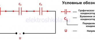
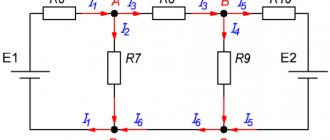
Let's look at ways to find points of equal potential in more detail. Let us be given an electrical circuit consisting of resistances R1, R2, ..., R8 (Fig. 1 a). Let's draw a straight line AB through the connection points of the circuit (Fig. 1 b).
1 way. If a circuit contains conductors with the same resistance, located symmetrically about a certain axis or plane, then the ends of these conductors have the same potential. In this case, the points will be symmetrical with respect to the straight line AB if the resistances of the circuit sections between these points and any points of this straight line are equal.
Using this feature, we can conclude that points C1 and C2 (Fig. 1 b) will be symmetrical with respect to straight line AB if R1 = R2 (resistances between points A and C1 and between points A and C2 are equal) and R5 = R6 (resistances between point B and C1 and between point B and C2 are equal). Similarly, points C3 and C4 will be symmetrical with respect to straight line AB if R3 = R4 and R7 = R8.
Method 2. Points have the same potential if the resistance ratios between these points and the connection points are equal.
For example, points C1 and C2 (Fig. 1 a) have the same potential if . Similarly, points C3 and C4 have the same potential if .
Let us show with examples how these methods can be used to transform electrical circuits.
Method of combining equipotential nodes: points with equal potentials can be connected into nodes.
a) If you draw a straight line AB through the connection points (Fig. 3 a), then the resistances of sections AC1 and AC2 are equal (R1 = R3), and the resistances of sections BC1 and BC2 are equal (R2 = R4). Consequently, points C1 and C2 are symmetrical with respect to straight line AB and have equal potentials.
Points with the same potentials can be connected into nodes (Fig. 3, b). Resistors R1 and R3 are connected in parallel, and resistors R2 and R4 are connected in parallel, sections 1/3 and 2/4 in series. Hence,
b) If you draw a straight line AB (Fig. 3 a), then the resistances of sections AC1 and AC2 are not equal, therefore, points C1 and C2 are not symmetrical with respect to straight AB. BUT points C1 and C2 have equal potentials, because .
Points with the same potentials can be connected into nodes (Fig. 3 b). Resistors R1 and R3 are connected in parallel, and resistors R2 and R4 are connected in parallel, sections 1/3 and 2/4 in series. Hence,
Example 2. Find the resistance of the wire cube between points A1 and B3 (Fig. 4). The resistance of each edge is R.
Points with the same potentials can be connected into nodes (Fig. 6). Three resistors R are connected in parallel between points A1 and A2 (B1, A4), six resistors R are connected in parallel between points A2 (B1, A4) and A3 (B2, B4), three resistors R are connected in parallel between points A3 (B2, B4) and B3, the sections between these points are connected in series. Hence,
Example 3. Find the resistance of the wire cube between points A1 and B2 (Fig. 4). The resistance of each edge is R.
Points with the same potentials can be connected into nodes (Fig. 7 b). Using the recurrent method, the circuit can be simplified (Fig. 7c or d).
Points A2 and B4 have equal potentials, because . Points with the same potentials can be connected into nodes (Fig. 7 d). The resistors in section A1A2 are connected in parallel, and the resistors in section A2B2 are connected in parallel, and these sections are connected in series. Hence,
If the union of two equipotential nodes is possible, then the reverse transition is also possible.
Node separation method: a circuit node can be divided into two or more nodes if the resulting nodes have the same potentials.
A prerequisite for this is to check the resulting nodes for equality of potential (symmetry or proportionality of resistance).
Example 4. Find the resistance of the circuit, which is a frame of identical pieces of wire (Fig. resistance R each.
Let's divide the node in the middle of the frame into two nodes O1 and O2 as shown in Fig. 9 a. This can be done since points O1 and O2 have equal potentials: the resistances of sections AO1, AO2 are equal, and the resistances of sections BO1, BO2 are equal. Let's redraw the diagram into a standard form (Fig. 9 b). Using the recurrent method, the scheme can be simplified (Fig. 9 c), because the resistance of section C1F1 is equal to , similarly. Then the total resistance of the circuit is .
Note. From a geometric point of view, points O3 and O4 are symmetrical with respect to straight line a (Fig. 9 d), but the potentials of these points are not equal, because the resistances of sections AO3 and AO4 are not equal, and the ratio of the resistances of sections AO3 and AO4 is not equal to the ratio of the resistances of sections BO3 and BO4.
Example 5. Find the resistance of a circuit that is a frame of identical pieces of wire (Fig. 10) with resistance R each.
Let's divide the node in the middle of the frame into three nodes O1, O2 and O3 as shown in Fig. 11 a. This can be done since points O1, O2 and O3 have equal potentials: the resistances of sections AO1 and BO1, sections AO2 and BO2, and sections AO3 and BO3 are equal, therefore, the resistance ratios of these sections are equal.
Let's redraw the diagram into a standard form (Fig. 11, b). Using the recurrent method, the circuit can be simplified (Fig. 11c), because the resistance of section C1F1 is equal to, similarly, the resistance. Then the total resistance of the circuit is
Literature
- Zilberman A. Calculation of electrical circuits // Quantum. – 1988. – No. 8. – P. 30-34.
- Petrosyan V.G., Dolgopolova L.V., Likhitskaya I.V. Methods for calculating DC resistor circuits // Physics. – 2002. – No. 14, 18, 22.
- Khatset A. Methods for calculating equivalent resistances // Quantum. – 1972. – No. 2. – P. 54-59.
What else does an electrician need to know - recommendations, tips, rules
Here we will learn some rules that will make further work easier. Some of them are closer to tips and tricks, but some are mandatory to know and follow.
First of all, we remember Ohm's law, which will help us calculate the current strength and select the appropriate wire cross-section. The formulation of the law looks like this: “the current strength in a section of the circuit is directly proportional to the voltage at the ends of this section and inversely proportional to its resistance,” which translated into Russian sounds like “the higher the voltage, the higher the current, but with increasing resistance, the current decreases” and is expressed formula I=U/R, where I is current, U is voltage and R is resistance. Knowing this formula will make it easier for us to choose the appropriate wire cross-section.
Ohm's law
Another useful thing is a little about wires. Recently, a third, grounding wire is often added to the wires of a single-phase network. So, the earth is always yellow with a green stripe. It is difficult to cast it from scratch using an indicator or tester, but it is very easy to do this using color markings. I will add to what has been said that it is customary to connect the zero to the blue wire.
And this rule should be remembered and always followed. Wires are often connected by twisting; this is an accepted practice and, in principle, quite acceptable. But there is one caveat - only wires made of homogeneous metals (for example, copper to copper) can be twisted together. When twisting copper with aluminum, an oxide film appears at the twisting site over time, which leads to an increase in resistance and possible fire.
When twisting copper with aluminum, an oxide film appears at the twisting site over time.
The magnetic properties of electric current were discovered by accident in 1820 by the Danish physicist Hans Christian Oersted (not to be confused with Andersen). As a result of one of his experiments, he noticed that the conductor through which it flows deflects the magnetic needle. Having learned about this discovery, Francois Arago makes an oral statement about it at a meeting of the French Academy. As a result of experiments, members of the Academy derive the laws of electromagnetism, which will later be taken as the basis for the creation of modern electromagnetic devices (electric motors, transformers, generators. Even radio waves are essentially electromagnetic radiation of ultra-high frequency).
So we figured out a little about the basics of electrical engineering (I will say more - some places were even devoted to radio engineering), which, in fact, turned out to be not at all so incomprehensible and confusing. Now that you have received the necessary knowledge, you can continue to move further in this direction. The main thing here is more confidence! And we, in turn, will constantly post more and more new tips and interesting information on the topic.
Video
Coffee capsule Nescafe Dolce Gusto Cappuccino, 3 packs of 16 capsules
1305 ₽ More details
Coffee capsules Nescafe Dolce Gusto Cappuccino, 8 servings (16 capsules)
435 ₽ More details
Full HD video cameras
Voltage representation
The easiest way to understand voltage is to imagine the pressure in a pipe. At higher voltage (pressure) a higher current will flow
While it is important to understand that voltage (pressure) can exist without current (flow), current cannot exist without voltage (pressure)
Voltage is often called potential difference because between any two points in a circuit there will be a difference in the potential energy of the electrons. When electrons flow through a battery, their potential energy increases, but when they flow through a light bulb, their potential energy will decrease, this energy will leave the circuit in the form of light and heat.
Take for example a regular 1.5V AA battery, there is a potential difference of 1.5V between the two terminals (+ and -).
Voltage or potential difference is simply a measurement of the amount of energy (in joules) per unit charge (coulomb). For example, in a 1.5 volt AA battery, each coulomb (charge) will receive 1.5 volts or joules of energy.
Voltage =
1 volt = 1 joule per coulomb
100 volts = 100 joules per coulomb
1 coulomb = 6,200,000,000,000,000,000 electrons (6.2 × 10¹⁸)
Induced voltage
The induced voltage on an idle current conductor is measured by applying short circuits provided for by the design. Measurements are taken mid-span between the short circuits. Using a portable voltmeter, alternately measure the voltage between different phases and between phases and ground.
| Symmetrical rigid conductors on support insulators. |
The induced voltage W can be significant, and to limit it when working on a disconnected circuit, short circuits are installed at the beginning and end of the conductor, and, if necessary, at its intermediate points so that the induced voltage does not exceed 250 V required by safety conditions.
The induced voltage U can be significant, and to limit it when working on a disconnected circuit, short circuits are installed. The number and location of short circuits is selected so that the U value does not exceed 250 V.
The induced voltage V can be significant and to limit it when working on a disconnected circuit, short circuits are installed at the beginning and end of the conductor, if necessary, and at intermediate points so that the induced voltage does not exceed 250 V required by safety conditions.
If the induced voltage is high, the two ends must be grounded. In this case, induced currents arise in the screen, which leads to additional heating of the cable. However, losses in the screen are still much less than losses in the central conductor, and the maximum additional heating is in the range from 1 to 3 C.
This induced voltage is amplified and recorded. It can be assumed that the rotating field H causes the coherence of spin precession, resulting in a macroscopic magnetic moment that precesses with frequency VQ. In another version of the circuit, the exciting and receiving coils are combined and the process of reorientation of the nuclei is detected as absorption of the energy of the RF field.
| AC voltage U. |
This induced AC voltage is subjected to half-wave rectification in the bridge converter of the cathodic protection station, increases the protective current and thereby causes a decrease in the pipe-soil potential. Since the operating current in a high-voltage overhead line or on a section of an electrified railway changes over time, a synchronous change occurs in both the induced voltage and, with it, the rectified alternating current, as a result of which the pipe-ground potential continuously fluctuates. Optimal setup of a cathodic protection station under such conditions becomes difficult or even impossible. Converters that are resistant to high voltage are also beneficial in this case, because their chokes sharply reduce the induced alternating voltage. As a result, the pipe-soil potential is stabilized.
The polarity of the induced voltage, depending on the relative position and direction of winding of the coils, may coincide (be consistent) or not coincide (be counter) with the accepted positive polarity of the voltage of the second coil.
The magnitude of induced voltages in semiconductor relays is significantly less than in electromechanical relays. The dead zones of these protections also have smaller values, and as a result, there may still be a loss of directionality of the relay action in the case under consideration.
The phase of the induced voltage is shifted relative to the current by 90 and can thus differ significantly from the phase of the electrostatically induced voltage. The action of higher harmonics of the transmission line current is proportional to frequency, as can be seen from relation (31.4), and can lead to disruption of the operation of telephone lines, especially since telephone lines are more sensitive to them than to the fundamental harmonic.
The chapter is devoted to the dangers of induced voltages and protection against them; here we will limit ourselves to only examples. The danger of such voltages is especially great if the vehicle is carrying fire and explosive cargo.
To reduce induced voltages on pipelines, grounding devices are mainly used. Protective groundings are installed in places on pipelines where pipeline voltages induced by an electrified railway exceed permissible limits.
In the zone of induced voltage, when working on wires (cables) performed from a telescopic tower or other mechanism for lifting people that does not have an insulating link, their working platforms are connected by means of a portable grounding to the wire (cable), and the tower or mechanism itself is grounded. The wire (cable) must be grounded at the nearest support.
Current measurement
Unlike voltage, which is measured at two points, current is measured at one point. Since the current strength (or they simply say current), according to our analogy, is the speed of water flow, this speed needs to be measured at only one point.
We need to cut the water pipe and insert a meter into the gap that will count liters and minutes. Something like this.
Similarly, if we return to the real world of our electrical model, we get the same thing. To measure the amount of electric current, we need to connect a simple device - an ammeter - to the open circuit of the electrical circuit. An ammeter is also included in the multimeter. You can also read my article.
The multimeter probes need to be switched to current measurement mode. Then we cut our conductor and connect the pieces of wire to the multimeter and voila - the current value will be shown on the multimeter screen.
Potential difference
Since electric current is the ordered movement of charged particles, to determine the magnitude of the current it is necessary to know both the energy value of the particles and the force of external influence on them.
The essence of the concept of potential difference
To study the properties of charged particles placed in an electrostatic field, the concept of potential was introduced. It means the ratio of the energy of a charge placed in an electrostatic field to its magnitude.
When a charged particle is transferred to another point in the field, its potential energy changes, but the magnitude of the charge remains unchanged. Transfer requires a certain amount of energy. This energy for transferring a unit of charge is called electrical voltage. Accordingly, a larger supply of energy will accelerate the transfer, that is, the higher the voltage, the greater the current in the circuit.
In this case, the potential difference is numerically equal to the voltage between the points where a unit charge is located. For the general case, the work of external forces must be added here, which is called electromotive force (EMF). At its core, electricity is the work of a third-party source (generator) to maintain specified voltage and current levels in an electrical circuit.
Unit of potential difference
What is potential in electricity
In honor of the scientist (Alessandro Volta), who first proved the existence of potential differences, the unit of measurement is named Volt. In the international system of units, voltage is indicated by the symbols:
- B – in Russian-language literature;
- V – in English-language literature.
In addition, there are multiple notations:
- mV – millivolt (0.001 V);
- kV – kilovolt (1000 V);
- MV – megavolt (1000 kV).
Magnetic induction vector flux
The electrostatic field is characterized by intensity, which, together with the vector of electromagnetic induction, constitutes the electromagnetic field.
If a charged particle moves in an electromagnetic field, then the total force that acts on the particle is determined by Lorentz’s law:
Where:
- q – charge value;
- v – speed of movement;
- E – electric field value;
- B is the magnetic induction vector.
Note! The indicated formula shows vector quantities. The cross indicates the vector product.
The force F acting on a particle is usually called the Lorentz force.
Magnetic induction vector flux
This formula is the most general and can be used for calculations under the condition of a point charge (including a unit charge).
Gauss's theorem for magnetic field
Electric field - what is it, concept in physics
Gauss's theorem is one of the most basic laws in electrodynamics. There are Gauss's theorems for electric and magnetic fields, which are part of Maxwell's equations.
Using this law, a connection is established between the strength of the electric field and the charge in the case of an arbitrary surface. Gauss's theorem (law) states that in an arbitrary closed surface the flow of the electric field vector is proportional to the charge contained inside the surface.
For a magnetic field, Gauss's theorem says that the flux of the magnetic induction vector through an arbitrary closed surface is zero.
Expression for the field potential of a point charge
Since the potential is equal to the integral of the field strength, we can substitute the expression for the field strength of a unit charge under the integral sign. After integration and transformation, the expression for the field of a point charge takes the form:
Where:
- ε0 – electrical constant;
- r – distance.
The above expression indicates that the amount of energy increases in proportion to the degree of charge and decreases in proportion to the distance.
Conductors in an electrostatic field
Placing a conductor in an electrostatic field causes the field to act on charge carriers inside the conductive object. The carriers begin to move until the electrostatic field outside the surface becomes zero.
Since there is no field inside the substance, the energy will be constant at all points of the conducting material, and the surface will be equipotential. Field strength vectors are directed at right angles at any point on the surface of the conductor.
Conductor in an electrostatic field
Under the influence of the field, there are no charges inside the conductor, since they are concentrated exclusively on the surface. This fact is used in shielding - protecting bodies from the influence of external electromagnetic and electrostatic fields. For shielding, not only solid conductive material can be used, but also a mesh, the so-called “Faraday cage”.
Also, the property of moving charged particles (electrons) is used in electrostatic generators to produce voltages of several million volts.
Electrical capacity of a solitary conductor
To connect the magnitudes of charge and voltage, the concept of electrical capacitance was introduced. For a solitary conductor (one that is not influenced by other charged bodies), the capacitance value is a constant value and equal to the ratio of the amount of charge to the potential. In other words, capacitance shows how much charge must be imparted to a conductor in order for its potential energy to increase by one.
Electrical capacity does not depend on the degree of charge. The role is played only by:
- form;
- geometric dimensions;
- dielectric properties of the medium.
Just like the capacitance of an electrical capacitor, the electrical capacitance of a conductor will be indicated in farads.
Note! In practice, the electrical capacitance of a conductor is very small. To increase the value, especially in the production of capacitors, as elements with a standardized capacitance value, special technologies have been developed.
Potential drop along a conductor
At the ends of a conductor placed in an electric field, a potential difference begins to be observed. As a result, electrons begin to move towards increasing the difference. An electric current arises in the conductor.
Free electrons move along the conductor until the difference is zero. In practice, to maintain a given current value, circuits are powered from voltage or current sources.
The difference is this:
- The current source maintains constant current in the circuit regardless of the load resistance;
- The voltage source maintains a strictly constant EMF at its terminals, regardless of the amount of current consumed.
The potential difference (voltage drop) is proportional to the distance from the ends of the conductor, that is, it has a linear dependence.
Volta's Experience
Alessandro Volta was the first to prove the existence of potential differences. For the experiments, two disks were taken, made of copper and zinc and mounted on the rod of the electroscope. When copper and zinc come into contact, the leaves of the electroscope move apart, indicating the presence of an electrical charge.
Based on his experiments, the scientist made the first source of electrical voltage - a voltaic pole.
Measuring contact potential difference
The main problem is that the contact potential difference cannot be measured directly with a voltmeter, although the value of the emf in a circuit connecting two different conductors can range from fractions to units of volts.
The contact potential difference significantly affects the current-voltage characteristic of the measured circuit. A good example is a semiconductor diode, where a similar phenomenon occurs at the interface between semiconductors with different types of conductivity.
How is voltage measured?
We measure voltage in units of "Volts", which are usually designated simply by the letter "V" on drawings and technical literature. It is often necessary to quantify the magnitude of voltage, this is done according to SI units, the most common voltage values you will see are:
- megavolt (mV)
- kilovolt (kV)
- volt (V)
- millivolt (mV)
- microvolt (µV)
Voltage is always measured at two points using a device called a voltmeter. Voltmeters are either digital or analog, with the latter being the most accurate. Voltmeters are usually built into handheld digital multimeters, as shown below, and are a common and often essential tool for any electrician or electrical engineer. You'll usually find analog voltmeters on older electrical panels such as switchboards and generators, but almost all new equipment will come with digital meters as standard.
Handheld Digital Multimeter with Voltmeter Function
On electrical diagrams, you will see voltmeter devices labeled with a V inside a circle, as shown below:
Electric field potential
An important property of the electric field, as a field that does not have vortices and is created by only stationary sources, is its potentiality
An electric field is called potential if the work done by a charge carrier in such a field when moving it along any closed contour is equal to zero.
The gravitational field of gravity is also potential
If you lift a load of a certain mass to a certain height, and then lower it back to the surface of the Earth, to the previous point, then the total mechanical work will also be zero.
Moreover, it does not matter at all what trajectory the load was lifted and lowered along. The source of such a gravitational field in this example is the Earth (a body with a mass many times greater than the mass of the lifted load).