Despite the dominance of computers, mobile phones and televisions in our lives, radio broadcasting still has its fans. Radio signals are received using a radio receiver, it is convenient to use in the background, during a long journey in a car, long runs and sports.
Radios are still a part of our lives
High-quality reproduced sound and normal volume of the radio signal can only be obtained by connecting the receiver to the antenna. At its core, this is a very simple design, so any technically competent person can make an antenna with their own hands.
Types of antennas
Any device that receives radio waves has a sensitivity threshold. If the received signal is lower than this, the sound volume and quality will be poor. The radio wave weakens when moving far away from the transmitting station or due to deteriorating weather. This is especially true for the FM and VHF bands due to the characteristics of wave transmission. To overcome these difficulties, strengthen and improve the signal quality, any radio needs an antenna. Their design features and dimensions are determined by the range of the receiver: there are multi-kilogram antennas with coverage of thousands of square meters. km and simple homemade crafts in the form of wire above the ground.
The whole variety of antennas for radio stations is divided into directional and non-directional, as well as mobile and stationary. Directional ones work on the principle of connecting point to point or point to many points within 50-100 meters. Non-directional ones have coverage over the entire area around them.
There are also such radio antennas as:
- Rod - in the form of a regular rod or a rounded shape;
- Wire – curved in various required positions;
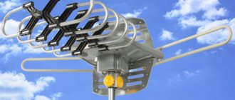
- On once fashionable boomboxes and music centers you can find telescopic antennas - folding structures made of metal rods, reminiscent of telescopes;
Telescopic antenna
- A retractable antenna is available on almost every car; its advantage is that such a retractable structure can be installed anywhere in the car (roof, fender, etc.), the receiving element is a removable rod with anti-noise winding, which allows you to make the radio sound clear and loud even at high driving speeds. The rod goes into a plastic casing, where there is a stainless steel spring, which retracts the antenna into place when it is deflected in the direction of travel.
Regardless of the type or type of radio antenna, their operating principles are the same.
Note! Quite often, the quality of a radio signal does not depend on the type and condition of the antenna for a radio receiver or music center, but on the technical capabilities of these devices themselves with their receiving chips.
Features of radio wave propagation
Before turning to step-by-step instructions on how to make an antenna yourself, it is necessary to clarify the features of radio signal transmission in the VHF and FM bands. This will help you better understand the principle and design of the antenna.
Important to remember:
- reception of a high-quality signal is possible only within visibility (for example, when a television and radio tower is visible from the window of a house);
- capturing a signal at a great distance from the broadcasting object in the evening and at night is problematic;
- precipitation weakens or completely interrupts signal transmission.
FM antenna design for receiver
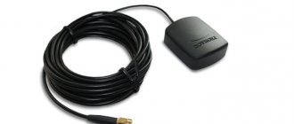
Phone antenna
Such antennas are designed to convert radio waves in the FM range into electrical signals perceived by the receiver. The simplest designs are a vibrator, half the size of a wave. Such antennas do not have directional properties and perceive too much interference radiation from the surrounding space. If the FM receiver is mobile, you can, by making some movements, find the best direction of the signal. For stationary receiving radio devices, a wave channel tuned to the broadcast receiving beam is more suitable, while the best sound quality will be on a couple of channels (mostly radio stations of this type broadcast in a range of about 10 megahertz).
Additional Information . If it is necessary to expand the radio broadcast beam, you can connect 2-3 half-wave vibrators in parallel in a vertical position and solder them onto round cylinders.
The required 50 ohm resistance is not always achieved; such an FM antenna must be amplified with devices for matching. Thus, vibrators can be mounted on cone-shaped guides, representing a fan, “opened” from the center to the borders.
FM antenna fanning out
When using steel and sheet metal in construction, it is possible to obtain even 300 ohms. Thus, it turns out to receive a fairly large number of FM channels. To further expand reception in this range, it is sometimes necessary to assemble and connect an antenna array.
Amplifier selection criteria
You can choose a suitable antenna amplifier for your car radio by taking into account various recommendations. They are as follows:
- To begin with, pay attention to the fact that the device must be located in close proximity to the antenna.
- The operating band must cover the required frequency range. Due to this, you will be able to listen to all available radio stations.
- The amplitude-frequency response should be as uniform as possible.
- The gain is selected in the range of 15-25 dB.
- Stability of operation must be ensured when the supply voltage varies.
- The dynamic range is selected taking into account the need to protect the device from overload.
- The noise figure is much less than the signal-to-noise ratio.
- It is recommended to give preference to devices from popular brands. They last much longer and have more attractive properties.
The FM frequency, when installed with a suitable amplifier, will be virtually interference-free. However, in some cases there is a possibility that such an element will cause noise at a high signal level.
Antenna connection
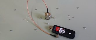
DIY Mimo 4g lte antenna
The antenna for the radio receiver is connected in several ways:
- Direct: the antenna (usually telescopic antennas) is an integral part of the receiving radio device, while the “ground” phase is its body itself. The (active) resistance with such a connection reaches thirty ohms, and the reactive one is removed by altering the resonance circuit. Such antennas are not symmetrical. The grounding must be reliable (the length of the bare wire must exceed 1/10 wavelength), otherwise interference due to loop radiation is possible;
- With non-resonant power supply: a transmission line is used for directional transmission of radio waves, and its characteristic impedance must be equivalent to the antenna impedance. This connection allows you to get rid of losses and provide the best radio signal level;
Important! The excess cable between the FM antenna and the radio receiver should be cut, because each additional meter greatly reduces the receiver's sensitivity. After matching the resistance, bringing it closer to 50 Ohms, radio signal reception improves significantly.
- With the resonant type of power supply of communication lines, the ease of passage of radio waves directly depends on the length of the wave itself. For such antennas, feeders of half the wavelength (or multiples) are chosen, and the wave resistance is no longer so important, the antenna is matched. The frequency that an FM antenna perceives is the carrier frequency, quite often these are sine waves with a leading frequency of 50 hertz (harmonics).
Schematic diagram
The amplifier circuit is shown in Fig. 1. It is made on a low-noise bipolar transistor. The gain is about 20 dB.
Rice. 1. Schematic diagram of an antenna amplifier for VHF receivers.
At the input of the amplifier, a series-connected low-pass filter (LPF) C1L1C2 with a cutoff frequency of 115.120 MHz and a high-pass filter (HPF) with a cutoff frequency of 60-65 MHz are installed.
Thus, the amplifier provides amplification of signals from radio stations operating in both VHF broadcasting bands.
If the amplifier is planned to be placed in a radio receiver that uses one antenna for all bands (car version), then its circuit must be modified and two relays introduced, as well as an additional power filter.
The device diagram of this option is shown in Fig. 2. When the supply voltage is applied, relays K1 and K2 connect amplifier A1 (shown on it) between the antenna and the receiver, and when the power is turned off, the input of the radio receiver is connected directly to the antenna.
If the amplifier will be installed in a car, then it must be placed in a metal case and power must be supplied through a pass-through capacitor (C9).
Rice. 2. Antenna amplifier connection diagram.
How to make a radio antenna
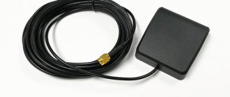
GPS antenna
If you have a technical mind and skillful hands, you can assemble a completely working radio antenna with your own hands. To do this you will need the following simple tools:
- a small coil of purified copper wire or metal foil;
- sharpened knife;
- pliers/cutters.
In the easiest case, you can take a ready-made television antenna and simply solder the connectors for the TV to those needed for the radio.
A homemade antenna for the VHF and FM bands can be constructed from the most ordinary foil or a piece of wire, only the sizes will vary.
The simplest indoor wire radio antenna
A homemade FM antenna is constructed on a dried board 15 by 15 centimeters using a sheet of foil 13 by 13 centimeters, thickness 15 mm (can be made up of several “shreds”). The algorithm of actions is as follows:
- on the foil we cut a square with a side of 1 decimeter, we get a frame;
- a 3 mm thin rectangle is separated from below;
- glue the resulting square frame onto plywood or a board to give the future antenna strength;
- to connect a shielded cable (its resistance is from 50 to 75 ohms), attach the central core of the antenna with a soldering iron to the bottom right;
- the screen is attached in the central part, shifted to the left by 2.5 cm.
For antennas in the VHF range, a plate is taken with a side of at least 18 centimeters, a foil square with a side of 15 and a half centimeters, and a frame thickness of 1.8 centimeters.
Not all FM radio signals have full coverage, which can be picked up by the built-in antenna. Signal amplifiers for an existing or self-made radio antenna come to the rescue. Sometimes it is enough to simply wrap a standard antenna with copper wire and bring its end out into the window. This tactic helps make the radio signal a little stronger, but does not improve the sound quality. In this case, the end of the wire must be carefully cleaned with a knife. Some radio enthusiasts insert their additional wire antenna into the socket on the rear panel of the music center, but this can damage the receiver and even short circuit the home network.
If the wire turns out to be powerless, you can design a rod-type antenna, which, being highly directional, better resists urban radio noise. The antenna-pin is made up of an arrow that acts as a power element, a pair of passive receiving devices (directors), a loop-type vibrator and a reflector-reflector. The dimensions of such a directional antenna are determined by the range to which the radio receiver will be tuned.
The whip antenna is assembled according to the following plan:
- a power structure is mounted on the façade of the building;
- into a pre-prepared socket on the radio/music receiver. a wire is inserted in the center;
- The found radio transmitting stations are configured.
More complex amplifiers of FM radio signals require solid knowledge and skills. Despite such efforts, waves can sometimes disappear at night (due to the lack of long-range perception of radio waves) and under unfavorable environmental conditions (rain, strong wind, heavy snow).
Add a link to a discussion of the article on the forum
RadioKot >Laboratory >Analog devices >
| Article tags: | AntennaAdd tag |
Working FM antenna
Author: Buster333, Published 10/29/2015 Created using KotoEd.
I would like to share my design of an FM whip antenna. I do this because I myself spent a very long time searching and experimenting in search of an acceptable and effective design. Maybe my story will help someone who is also concerned about this problem and finds it difficult to solve it. The need to make a good FM antenna arose due to the fact that my country house is located in a small provincial town-semi-village - Khvalynsk, Saratov region, 70 - 150 km away from broadcasting centers. The settlement is also located on the right bank of the Volga among old chalk mountains and hills, which are an additional obstacle to the passage of radio waves. But I didn’t give up the idea of making an antenna capable of receiving at least a few of the closest radio stations, although the local aborigines told me that it was useless, they didn’t have radio reception, only satellite TV. After reading specialized literature and articles on the Internet, I settled on a whip antenna with counterweights of the “Ground Plane” type, or “GP” for short, as the most optimal and universal for reception in the FM range, where most transmissions are in vertical polarization. I installed the antenna above the roof of the building (at a height of about 12m from the ground), where on the first floor there is a garage and a workshop, where I spend a lot of time, and on the second there are rooms for children’s games. At home you can also listen to the radio on Tricolor TV. The antenna design is a 1/4 broadcast wavelength rod that is isolated from the mast and counterweights. (photos 1 and 2). The counterweights are mounted radially to the post at an angle of 135 degrees to provide a characteristic impedance of 50 ohms. The feeder coaxial cable also has a characteristic impedance of 50 ohms.
Photo 1.
Photo 2.
Due to the fact that I assumed to receive radio in the range of 87 - 108 MHz, the pin dimensions are 0.75 m, which corresponds to ¼ wavelength (3 m) of the frequency of this 100 MHz range, around which the broadcast stations of interest to me are concentrated. By changing the lengths of the rod and counterweights, you can tune the antenna to a different frequency. The length of the counterweights is also taken to be 0.75 m, since the counterweights must be equal in length to the length of the main pin. The optimal number of counterweights to ensure acceptable antenna efficiency is 12. With a smaller number, the efficiency decreases, with a larger number, it increases insignificantly. An ideal whip antenna has an efficiency of 47%. The efficiency of an antenna with three counterweights is less than 5%, with 12 counterweights it is about 19%. I tested an antenna with three counterweights. The reception in my location was weak, with acceptable quality - 2-3 stations. I had to make a signal amplifier. Reception has improved to 5-6 stations with acceptable quality. But that didn’t suit me either. Therefore, in the end, it was decided to make another antenna, the one that I am now describing. Now about the antenna design. The pin and counterweights are made of an aluminum tube with a diameter of 8 mm, which I bought at the OBI hypermarket (7 two-meter sections for about 100 rubles each). To mount the pin and counterweights, a turner I know made me a load-bearing washer from aluminum with a shank with an outer diameter of 22 mm and a through inner hole of 14 mm, which is inserted into the mast from a 25-inch pipe (inch, actual inner diameter 23 mm) and fixed to the mast with an M6 bolt through the radial threaded hole in the mast. A textolite (or caprolon) bushing with an upper flange 10 mm high, an outer diameter of 14 mm, and an axial hole of 8 mm is inserted into which a pin is inserted, fixed with two diametrically opposed M4 screws in the threaded holes of the textolite bushing. 12 radial holes (15 degrees apart) for counterweights were drilled along the diameter of the aluminum washer. The counterweights are fixed in the holes using 12 M4 screws. (photo 3).
Photo 3.
The pin is made longer than 0.75 m, taking into account the fact that its lower end is flattened at a length of 10 mm, where a hole is drilled for the screw securing the central core of the coaxial cable, and also taking into account the fact that it must be inserted into the textolite sleeve until it stops in the flattened end so that its size above the aluminum washer is 0.75 m. Counterweights are also manufactured with a length greater than 0.75 m, taking into account the fact that their ends bent at an angle of 45 degrees are inserted into the radial holes of the supporting washer. In the holes they are secured from turning, as I already said, with M4 screws. I would like to draw your attention to the fact that the counterweight tube is fragile and must be bent by 45 degrees very carefully, preferably in a bending device. At the lower end of the hollow aluminum shank of the washer there is an M3 threaded hole for fastening the braided coaxial cable with a screw and washer. Since the washer of this screw can extend beyond the outer diameter of the 22mm shank due to the fact that its diameter is greater than the thickness of the aluminum wall, in the pipe mast at the end where this shank will be inserted, I made a through cut approximately 7mm wide along the pipe at a length slightly greater than the length of the shank supporting aluminum washer. Now there is nothing in the way, and you can insert the assembled antenna into the mast and secure it with an M6 bolt. The lowering cable runs inside the mast. Since the antenna pin has no electrical contact with the mast, it will develop a static charge under certain conditions. At best, it will cause interference in the form of a crackling sound; at worst, it can lead to failure of the receiver’s input path. Especially during a nearby thunderstorm. The structure must be grounded. I did it as follows. The mast was connected to the grounding loop of the building (the grounding loop must have a resistance of less than 4 ohms, then it is considered effective and capable of performing its function) with a cable with a cross-section of 25mm2 See photo 4.
Photo 4.
The antenna pin cannot be connected to ground directly; the antenna will become short-circuited and will not work. The simplest method of protection is to use a short-circuited cable made of L/4 length cable connected to the feeder using a tee. The cable provides a DC connection between the central core of the feeder and the grounded braid and does not affect the antenna matching. The cable connection diagram is shown in Fig. 10.3.
The loop length of ¼ wavelength is calculated and does not take into account the wave shortening factor when passing through the cable (coaxial cable shortening factor). In my case, the RK50-4-11 cable was used, the shortening factor of which is 0.66. It may be different for another cable, and you need to check it in the manual. Thus, the length of the cable is determined:
L = 1/4 x 3m x 0.66 = 0.495m, where 3m is the wavelength at a frequency of 100 MHz.
I used such a coordinated loop to remove static from the antenna pin. How this was done practically can be seen in photos 5 and 6.
Photo 5.
Photo 6.
A thin yellow-green wire is soldered to the end of the central core of the cable and connected to the “ground” on the same bolt clamp on the mast as the 25mm2 ground cable (see photo 4). The antenna turned out to be very successful. It provides reception with acceptable or excellent quality (in stereo mode) of about 20 radio stations in the cities of Samara, Tolyatti, Syzran (Samara region), Balakovo, Pugachev (Saratov region) without the use of a signal amplifier. In photo 6, the receiver the antenna works for is Grundig Satellit 750. I also tried it with other receivers, less sensitive and selective, the result is somewhat worse, but still acceptable.
Photo 7.
So the myth of the local population about the absence of any kind of radio reception in the “village-type” city of Khvalynsk, where my country house is located, collapsed for me unconditionally and completely.
All questions in the Forum.
| What do you think of this article? | Did this device work for you? | |
| 67 | 8 | 0 |
| 0 | 0 |
These articles may also be useful to you:
Mini stereo FM.
FM organ with digital control
Simple FM receiver with clock and alarm clock
Digital FM receiver with electronic volume and tone control.
FM transmitter on STM32F100 and KT0803K + a little about technology and China
Portable FM receiver on the RDA5807M radio module with RDS
FM stereo tuner (88-108 MHz) with built-in CCTR stereo decoder.
Miniradio FM
FM radio on RDA5807M with Nokia5110 display.
Simple FM receiver with clock and thermometer
FM STEREO Receiver on TEA5767 module with LCD NOKIA 3310 and Touchscreen
Ferrite antenna for SDR
DIY pipe antenna
The main supporting element of this radio antenna is heating or water pipes. Required materials for creation:
- used transformer core (from an old TV);
- electrical tape, tape, office glue;
- foil made of thin copper or brass;
- one and a half meters of copper wire (diameter ¼ sq. mm);
- connecting pins.
For winding, the first layer is a ferrite core, a couple of layers of electrical tape on top, followed by a single foil layer. Exactly 25 turns of wire are wound onto such a screen blank with an overlap of 1 centimeter for better contact insulation. You should remember about the mandatory taps on turns No. 7, 12 and 25. The circuit is connected to other parts, and the ends of the wire are inserted into the pins. The tap from the 7th turn is inserted into the grounding socket, and the remaining two are connected to the antenna terminals.
The final stage is setting up the radio signal reception; this is done by simply selecting the connection of the winding to the connected circuit. Such homemade radio antennas reliably receive a signal even in a severe thunderstorm, thanks to reliable grounding.
If the radio receiver is located in an area where the reception is very weak and of poor quality, you can assemble an omnidirectional antenna yourself using a coaxial cable. For this you need:
- wooden slats;
- one and a half meters of cable (television cable is best);
- one and a half meters of PVC pipe (section diameter 2 cm).
Homemade antenna from coaxial cable
Constructing such an antenna is quite simple. A cut is made on the wire to remove the insulating layer (but the braid must remain intact, this is important!). Having loosened and slightly stretched the braid, the screen is turned out to the place of the cut. The final stage is to install and securely fasten the antenna inside the plastic tube and mount it on a wooden rail. The adjustment to search for a radio station signal is made in the vertical direction, and not by rotating the homemade antenna 360 degrees.
In dachas, in cars, even in urban built-up areas, those who like to listen to the radio are well aware of the problem of a weak signal and quiet sound of radio transmissions, especially in the FM range. Antennas for radios of various types and types of signal reception help correct the situation. They can be purchased in special stores, or you can make them yourself; fortunately, the technology is simple, and the parts can be bought at any radio market.
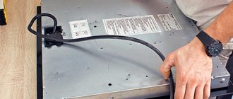
ANTENNA AMPLIFIER FOR CAR RADIO
All car enthusiasts have radios in their cars, but not all radios pick up the radio well. Only expensive devices are equipped with serious receivers with good UHF, capable of receiving weak FM stations. Most cheap car radios only work acceptably in the city, so it makes sense to equip them with an antenna amplifier. There are two options here - buy a ready-made industrial one or solder it yourself.
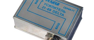
Antenna amplifier Ratex
For those who have some amateur radio skills, a couple of circuits of such amplifiers are offered.
The input coil L1 consists of four turns of enameled copper wire (frameless) on a mandrel more than 5 mm in diameter. Coil L2 is similar to L1, but has only three turns. The pinout of the 2SC2570 is shown in the diagram.