As you know, no load more powerful than an LED can be connected to the Arduino directly, especially motors. Arduino, and indeed any microcontroller in general, is a logical device that can only give logical signals to other pieces of hardware, and they can already control the load. By the way, I also have a lesson on managing powerful DC and AC loads. The “driver” of the motor can be different pieces of hardware, let’s look at some of them.
Relay
Using a regular relay, you can simply turn the motor on and off using the digitalWrite(pin, state) command, just like an LED:
Using a double relay module (or just two relays), you can turn the motor on in one direction or the other, as well as turn it off:
You can buy a relay module Relay aliexpress, aliexpress, search
Mosfet
A field-effect transistor, also known as a mosfet, allows you to control the rotation speed of the motor using a PWM signal. When using a mosfet, you must install a diode, otherwise the inductive surge from the motor will very quickly kill the transistor. The motor speed can be set using Arduino analogWrite(pin, speed).
Instead of a “bare” mosfet, you can use a ready-made Chinese module:
You can buy a mosfet module on Aliexpress: Mosfet module aliexpress, aliexpress, search
Relay and mosfet
If we combine a relay and a mosfet, we get a very collective farm, but working scheme for controlling the speed and direction of the motor:
Special driver
It is best to control the motor using a special driver; they come in different shapes and sizes and are designed for different voltages and currents, but they are controlled almost the same. Let's look at the main drivers from the Chinese market:
| Driver | Vmot | Current (peak) | ~Cost | Aliexpress |
| L298N | 4-50V | 1A (2A) | 100r | Buy |
| MX1508 | 2-9.6V | 1.5A (2.5A) | 20r | Buy |
| TA6586 | 3-14V | 5A (7A) | 100r (chip 30r) | Buy |
| L9110S | 2.5-12V | 0.8A (1.5A) | 50r | Buy |
| TB6612 | 4.5-13.5V | 1.2A (3A) | 80r | Buy |
| BTS7960 | 5.5-27V | 10A (43A) | 300rub | Buy |
| Big | 3-36V | 10A (30A) | 700rub | Buy |
See my other drivers here. Connection diagrams and control tables:
Direction pins are controlled using digitalWrite(pin, value), and PWM is controlled using analogWrite(pin, value). There are two options for controlling the driver using two pins:
// === first type, most common === // forward digitalWrite(pinA, 0); analogWrite(pinB, value); // value 0.. 255 // back digitalWrite(pinA, 1); analogWrite(pinB, 255 - value); // value 0.. 255 // === second type, for example large driver === // forward digitalWrite(pinA, 0); analogWrite(pinB, value); // value 0.. 255 // back digitalWrite(pinA, 1); analogWrite(pinB, value); // value 0.. 255 // the difference is that the PWM does not need to be inverted like 255 is a value!
Interference and protection against it
Inductive voltage surge
The motor is an inductive load that creates inductive surges when switched off. The motor has brushes, which are a source of sparks and interference due to the same inductance of the coil. The motor itself does not consume energy very evenly, which can cause interference along the power line, and the starting current of the motor is generally much higher than the operating current, which is guaranteed to drain the weak power supply during startup. All four sources of interference can lead to various glitches in the operation of the device, including the activation of buttons on digital pins, interference on analog pins, sudden freezing and even rebooting of the microcontroller or other hardware in the device assembly. You can cut off inductive emissions from the motor using the most ordinary diode; the more powerful the motor, the more powerful the diode is needed, that is, for a higher voltage and current. The diode is placed counter parallel to the motor, and the closer to the body, the better. It is recommended to do exactly the same with solenoid valves, solenoids, electromagnets and any other coils in general. It is logical that a diode should be installed only if the motor or coil is controlled in one direction. Important points:
- When working with the driver and control, it is not necessary and even impossible to install a diode in both directions!
- When controlling a PWM signal, it is recommended to install high-speed diodes (for example, 1N49xx ) or Schottky diodes (for example, 1N58xx ).
- The maximum diode current must be greater than or equal to the maximum motor current.
- A protective diode that absorbs the reverse surge of self-induction EMF is also called a shunt diode, snubber, flyback diode.
- In nature, there are mosfets with a built-in protective diode. This diode is a separate element and such a mosfet usually has a non-standard case; read the documentation for the specific transistor.
- The diode that is shown in the schematic diagram of the mosfet is not a protection diode: it is a weak and slow “parasitic” diode formed during the production of the transistor. It will not protect the mosfet from emission; you must install an external one!
Interference from brushes
The sparkling brushes of a motor, especially an old and broken one, are a strong source of electromagnetic interference, and here the problem is solved by installing ceramic capacitors with a capacity of 0.1-1 uF on the motor terminals. The same capacitors can be placed between each terminal and the metal case, this will further suppress the interference. To solder to the body, you need to use a powerful soldering iron and active flux to tin and solder as quickly as possible without overheating the motor.
Power supply interference, drawdown
The motor does not consume current very evenly, especially during acceleration or under conditions of variable load on the shaft, which manifests itself in the form of voltage drops in the power supply to the entire circuit. Problems with power supply can be solved by installing capacious electrolytic capacitors for power supply; it is logical that they should be installed as close as possible to the driver, that is, before the driver. The voltage must be higher than the supply voltage, and the capacity is already selected according to the fact. You can start with 470 uF and increase until it feels good.
Power sharing
If the methods described above do not help, there is only one thing left: power sharing. A separate low-noise good source for the MK and sensors/modules, and a separate one for the power part, including the motor. Sometimes, for the sake of stability, it is necessary to introduce a separate power supply or a separate battery for reliable operation of the device.
Shielding
In some cases, even interference from the supply wires of motors is critical, especially when controlling PWM powerful motors and controlling powerful steppers in machine tools. Such interference can create strong interference for sensitive electronic components operating nearby, on analog circuits, interfere with ADC measurement lines and, of course, interfere with radio communications. You can protect yourself from such interference by shielding power wires: it’s not always possible to buy shielded power wires, so it’s enough to wrap regular wires with foil and connect the screen to GND of the power supply. This trick is often used by RC modelers flying FPV.
1What is a motor driver and what is it for?
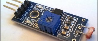
The maximum current at the Arduino pins is weak (about 50 mA) for such a powerful load as an electric motor (tens and hundreds of milliamps). Therefore, you cannot connect an electric motor directly to the Arduino pins: there is a risk of burning the pin to which the motor is connected. To safely connect electric motors of different types to Arduino, you need a homemade or industrially manufactured so-called. motor driver . Motor drivers are different; chips like HG788, L9110S, L293D, L298N and others are often used for their operation. Motor drivers have power supply terminals, terminals for connecting electric motors, and control terminals.
Various motor driver options
In this article we will use a driver to control motors based on the L9110S chip. Typically, boards are produced that support connecting multiple motors. But for the sake of demonstration, we'll make do with one.
Important Pages
- GyverKIT kit - a large Arduino starter kit of my design, sold in Russia
- Catalog of links to cheap Arduins, sensors, modules and other hardware from AliExpress from trusted sellers
- A selection of libraries for Arduino, the most interesting and useful, official and not so
- Complete documentation on the Arduino language, all built-in functions and macros, all available data types
- A collection of useful algorithms for writing sketches: code structure, timers, filters, data parsing
- Video lessons on Arduino programming from the “Arduino Engineer's Notes ” channel are some of the most detailed in RuNet
- Support the author for his work on the lessons
- Feedback - report an error in the lesson or suggest an addition to the text ( [email protected] )
4.6 / 5 ( 10 votes)
2 Connection diagram of the commutator motor and motor driver to Arduino
The simplest electric motors are commutator motors . Such motors have only two control contacts. Depending on the polarity of the voltage applied to them, the direction of rotation of the motor shaft changes, and the magnitude of the applied voltage changes the rotation speed.
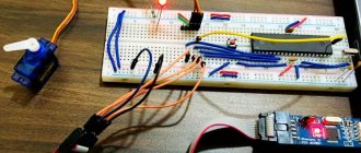
Let's connect the motor according to the attached diagram. The motor driver is powered by 5 V from the Arduino; to control the rotation speed of the motor rotor, the control contacts are connected to the Arduino pins that support PWM (pulse width modulation).
Diagram for connecting a brushed motor to Arduino using a motor driver
It should look something like this:
The motor is connected to the motor driver and Arduino
This tutorial uses:
| Arduino Uno: | Buy |
| Infrared range finder: | Buy |
| High precision laser rangefinder with I2C: | Buy |
| A set of 100 resistors for all cases: | Buy |
| Small motor: | Buy |
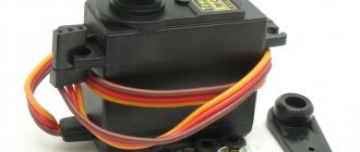
| Weak servo: | Buy |
| Powerful servo drive: | Buy |
| Mosfet transistor for high voltage AC control: | Buy |
| Set of NPN transistors of 100 pieces: | Buy |
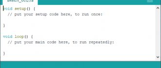
3Sketch for controlling a commutator motor
Let's write a sketch to control a commutator motor. Let's declare two constants for the legs that control the motor, and one variable to store the speed value. We will transmit the values of the Speed variable to the serial port and thus change the speed (by the value of the variable) and the direction of rotation of the motor (by the sign of the number).
int Speed = 0;
const int IA1 = 5; // Control pin 1 const int IA2 = 6; // Control pin 2 void setup() {
pinMode(IA1, OUTPUT);
pinMode(IA2, OUTPUT); Serial.begin(9600); } void loop() {
if (Serial.available() > 0) { String s = Serial.readString();
Speed = s.toInt(); // convert the read string into a number } if (Speed > 0) { // if the number is positive, rotate in one direction analogWrite(IA1, Speed); analogWrite(IA2, LOW); } else { // otherwise we rotate the rotor in the other direction analogWrite(IA1, LOW); analogWrite(IA2, -Speed); } }
The maximum rotation speed is at the highest voltage value that the motor driver can produce. We can control the rotation speed by applying voltages ranging from 0 to 5 Volts. Since we are using digital pins with PWM, the voltage on them is regulated by the command analogWtirte(pin, value) , where pin is the pin number on which we want to set the voltage, and the value argument is a coefficient proportional to the voltage value, taking values in the range from 0 (pin voltage is zero) to 255 (pin voltage is 5 V).
Let's load the sketch into the Arduino memory. Let's launch it. The motor shaft does not rotate. To set the rotation speed, you need to send a value from 0 to 255 to the serial port. The direction of rotation is determined by the sign of the number.
Let's connect to the port using any terminal, transmit the number “100” - the engine will begin to rotate at average speed. If we apply “minus 100”, then it will begin to rotate at the same speed in the opposite direction.
Controlling an electric motor using a motor driver and Arduino
And this is what the connection looks like connecting a commutator motor to Arduino in dynamics:
DC motor
Wikipedia says that a DC motor (DC motor) is a direct current electrical machine that converts direct current electrical energy into mechanical energy.
That is, from electricity we get mechanical movement.
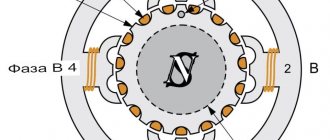
Electric motor diagram
When voltage is applied, current passes through the field winding. At adjacent poles, opposite polarity occurs, resulting in a magnetic field.
A direct current is supplied to the motor armature through the collector, which is acted upon by electromagnetic induction from the magnetic field of the stator.
The result is a torque that turns the rotor 90 electrical degrees. After this, the brush-commutator assembly switches the rotor windings so that rotation continues.
Description of the library for working with a stepper motor
In the Arduino IDE development environment there is a standard library Strepper.h for writing stepper motor programs. Main features in this library:
- Stepper(number of steps, contact numbers). This function creates a Stepper object that corresponds to the motor connected to the Arduino board. The argument is the contacts on the board to which the motor is connected, and the number of steps that are taken to complete a full rotation around its axis. Information on the number of steps can be found in the documentation for the motor. Instead of the number of steps, an angle can be specified, which is one step. To determine the number of steps, you need to divide 360 degrees by this number.
- Set Speed(long rpms) – a function that specifies the rotation speed. The argument is a positive integer indicating the number of revolutions per minute. Set after the Step() function.
- Step(Steps) – rotate by the specified number of steps. The argument can be either a positive number - turning the motor clockwise, or a negative number - counterclockwise.
Program and scheme
Today we will try to assemble a simple circuit; we will not use drivers and microcircuits to control the motor. Let's just connect the motor to the Arduino to turn it on and off. Since our motor runs on 5+ volts, no additional power is required. And we will turn on the motor from the sketch in the same way as the LEDs. Using a simple digitalWrite()
Schematic diagram of motor connection
Spin up and stop the electric motor