We continue the discussion of inductors , in the first part (link) we discussed all the main aspects, namely the design of the coils, the principle of operation and their behavior when used in DC and AC circuits. But some points remained untouched; in fact, we will discuss them in this article. And let's start with a very important characteristic, namely the quality factor of the inductor.
Calculation of capacitors
In general, the capacitance index C is determined by the formula:
C=q/U,
where q is the charge of the capacitor on one of its plates, U is the voltage value across the capacitor.
From this expression we can derive a formula for the charge of a capacitor, the value of which can be found by measuring the other two indicators using a multimeter.
The question often arises whether this setting can change. It is a constant value inherent in a given element and depending on its dimensions and design. You can find out the capacitive value using a multimeter. Using this data, you can calculate the target inductance of the inductor for the oscillating circuit or the parameters of the resistor.
How is capacitance measured? The measuring unit is taken to be the parameter of a capacitor device, which can be charged with 1 C to a state where the potential difference is equal to 1 volt. The name of this unit is farad (F).
Important! If we compare two devices that are identical in size, but differ in that one has dielectric material in the gap between the plates, and the other has air space, then when identical charges are placed, the potential difference of the first part will be E times greater. E is a number equal to the dielectric constant of the material that makes up the used layer. Below are the formulas for capacitor elements of different configurations
The values calculated from them correspond to ideal devices, but are also relevant for real ones in cases where capacitive losses can be neglected
Below are formulas for capacitor elements of different configurations. The values calculated from them correspond to ideal devices, but are also relevant for real ones in cases where capacitive losses can be neglected.
Formula for the electric capacitance of a flat capacitor
In the main electric field of the plates of a flat capacitor, it is uniform, with the exception of the side parts, the influence of which is usually neglected. However, if the space between the plates is large compared to their dimensions, edge distortion must be taken into account. In general, to calculate how many farads the capacitance of a flat capacitor will be, use the expression:
Series and parallel connection of resistances
C=E*E0*S/d, where S is the area of the smaller plate, E0 is the electrical constant, d is the length of the space between the plates.
Formula for the electrical capacitance of a cylindrical product
Such a component consists of a pair of coaxial cylindrical conductor elements of different sizes, with dielectric material placed in the space between them. In this case, to find the capacitive value, it is not necessary to find out the value of the charge on the capacitor plates. You can use the following capacity formula:
С=2 π *E*E0*l / ln(R2/R1).
Here R1 and R2 are the radii, respectively, of the inner and outer cylinders, l is their height (it is the same, while the radial parameters are different).
Cylindrical product
Formula for a spherical product
The spherical part consists of two conductive spheres with a dielectric layer between them. Here's how to find the capacitance of a circular capacitor:
C=4 π *E*E0* R1* R2 / R2 – R1.
The letters R indicate, as in the previous example, the radii of the components.
Capacitance of a single conductor
This is a characteristic of the ability of a solid conductive component to hold an electrical charge. It is determined by the characteristics of the environmental environment (in particular, dielectric constant), the relative position of bodies carrying a charge, and the dimensions of the part. It does not depend on the current strength and the amount of charge.
Online resistor connection calculator. parallel connection of resistors
Inductance
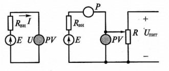
Above we considered two basic concepts in electrical engineering - an ideal voltage generator and an ideal current generator.
An ideal voltage generator produces a given voltage U (pressure in a plumbing analogy) at any load (external circuit resistance).
Moreover, in accordance with Ohm's law, I=U/R, even if R tends to zero and the current increases to infinity.
The internal resistance of an ideal voltage generator is 0.
An ideal current generator produces a given current I (flow in the plumbing analogy), even if the resistance of the external circuit tends to infinity. The load voltage also tends to infinity U=I*R.
The internal resistance of an ideal current generator is ∞.
Here you can see a certain symmetry, dualism.
We considered a capacitor C that can accumulate charge (that’s why it’s called capacitance) C=Q/U. The larger the capacitance, the slower the voltage (pressure) increases when charge U=Q/C is pumped into the capacitor.
If the charge capacity is very large (tends to infinity), then such a capacitor of infinite capacity will be an ideal voltage generator . It will never discharge and at the same time can produce a current of any magnitude, and the voltage across it will remain constant.
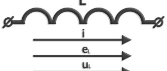
The element symmetrical (dual) to the capacitor will be inductance . Inductance is designated by the letter L (see diagram below).
Usually the electronic component itself is called an inductor , and its parameter is the inductance L.
Figure 13. Connecting the inductor to the voltage generator.
If a capacitor is a voltage generator, then an inductance is a current generator. Inductance strives to maintain the current in the circuit constant, that is, it prevents the current in the circuit from changing.
An inductance of infinite magnitude is an ideal current generator , that is, it will endlessly drive a given current I regardless of the load resistance.
As it is well said in the wiki - “When comparing the strength of electric current with speed in mechanics and electric inductance with mass in mechanics, the self-inductive emf is similar to the inertial force.”
It's like if you walk up to a trolley standing on the rails and start pushing it (applying force to it). The trolley will begin to slowly accelerate and “the current will run faster and faster through the wires.” And then try to brake the trolley and it will slowly stop.
So in inductance, after applying voltage, the current will gradually increase (the trolley accelerates), and when a voltage of a different polarity is applied, it will gradually decrease (the trolley decelerates).
This leads to the conclusion: “The train cannot be stopped instantly!”
“The current in the inductance cannot be stopped instantly!”
That is, even if you click switch S4 in the diagram and open the circuit, the current will continue to flow for the first moment after that! In practice, this leads to the fact that at the moment the contacts in the switch open, a spark will jump between them.
When the contacts are opened, the resistance increases to infinity (in reality, to very large values) and the flowing current will create a very large voltage across this resistance, so that the air gap between the contacts will be broken.
In a plumbing analogy, this phenomenon can be compared to a water hammer, when the mass of water in the water supply picks up speed, and when the tap is abruptly closed, the water, continuing to move by inertia, creates high pressure, which can lead to a pipe rupture.
The reasons why inductance has such properties (maintaining current in the circuit) are well described in the wiki - https://ru.wikipedia.org/wiki/Self-induction
“When the current in a circuit changes, the magnetic flux through the surface bounded by this circuit also changes proportionally. A change in this magnetic flux, due to the law of electromagnetic induction, leads to the excitation of an inductive emf in this circuit. This phenomenon is called self-induction. The direction of the self-induction EMF always turns out to be such that when the current in the circuit increases, the self-induction EMF prevents this increase (directed against the current), and when the current decreases, it decreases (co-directed with the current). The phenomenon of self-induction manifests itself in the slowing down of the processes of disappearance and establishment of current.”
In relation to a capacitor, the main difference between inductance, in simple terms, is that a capacitor passes alternating current and does not allow direct current to pass, while inductance, on the contrary, passes direct current and does not allow alternating current to pass through.
There is a certain point here - direct current is a current that does not change over time, what is called the “constant component” with a frequency of 0 Hz. Its capacitor does not pass. At all.
But inductance does not allow alternating current of infinite frequency to pass through at all. It’s just that alternating current of any finite frequency lets through a little.
But we will return to the concept of AC voltage later.
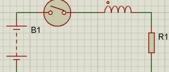
Consider the circuit in Fig. 13 - connection of the inductor to the voltage generator. Below is a graph of the current in the inductance when a constant voltage is applied to it from a voltage generator.
rice. 14 Graph of the current in the inductance when a constant voltage is applied to it.
When a constant voltage is applied to the inductance, the current in it increases linearly with time.
We remember a similar picture for a capacitor.
The voltage across the capacitor increases linearly when it is charged with constant current.
What happens if you power the inductance from a current generator?
Figure 15. Connecting inductance to a current generator.
Well, this is from the series “who will take whom - an elephant or a whale.”
Try to analyze the operation of the circuit (hint - in general the circuit is depicted with an error. What is it? How to draw the circuit correctly?)
Circuits containing a capacitor and inductor
As noted above, inductance in electrical engineering plays the same role as mass in mechanics. What is the analogue of a capacitor in mechanics? The capacitor is a voltage generator, that is, it creates a force that moves the flow of charge through the wires. Above, we presented an analogue of a capacitor in the form of a water tower, which is filled with water (charge) and the pressure (voltage) in it increases.
But you can also imagine a capacitor in the form of a spring - when charged, the spring compresses and the compression force (voltage) increases. The capacitance in this case is the reciprocal of the spring stiffness. The stiffer the spring, the faster the compression force increases. That is, the connection of a capacitor and inductance is equivalent to a trolley mounted on a spring. )
What will happen if a capacitor is connected to an inductance, for example, as in the circuit in Fig. 16
Figure 16. Parallel connection of a capacitor and inductor.
Let capacitor C be charged to voltage U. Switch S2 closes and current begins to flow in the circuit. This is equivalent to compressing a spring and then releasing it at some point (closing switch S2).
At the first moment after the switch is closed, the current in the circuit will be equal to 0, since inductance prevents the current from changing. A force is applied to the trolley, but at the first moment of time its speed is 0. Then the current begins to increase (the trolley accelerates). The spring expands more and more, the speed of the trolley (current) increases and at some point in time the spring is not compressed. The capacitor has discharged to 0. But. We remember that “the current in an inductance cannot be stopped instantly!” The trolley has accelerated and even if we don’t push it, it will move by inertia. That is, the inductance will maintain the current and at the same time charge the capacitor, but in a different polarity - the charges will now accumulate on the other plate of the capacitor. The growing voltage of the opposite sign on the capacitor will impede the movement of charges, and eventually the current in the circuit will become zero. But at the same time, the capacitor has already been charged with voltage U of a different polarity!
That is, the circuit has reached a state when the capacitor is charged, the current in it is zero. Hmm.. but this is the same state with which we started, only the polarity of the voltage is opposite. Consequently, the process will repeat, only the current will flow in the other direction and the system will return to its original state. The trolley will go back, pass the equilibrium position and, by inertia, compress the spring again.
An oscillatory process will occur. That is, the trolley on the spring will continue to roll back and forth, and in the absence of energy loss (friction), this process will last indefinitely.
Thus, the connection of a capacitor with an inductance forms an oscillating link. Such links are widely used in electrical engineering to create alternating current voltage generators and filters.
We will consider the concept of alternating current in the next article.
UPD. Since a dispute has arisen whether the current increases exponentially when connecting an inductor to a voltage generator or linearly, I will say a few more words on this issue.
Where does the exponential of current growth in the circuit in Fig. 13 come from? The answer is out of nowhere. She is not there. The current increases linearly and the dependence of the current on voltage is described by the formula
The self-induction emf in a circuit is directly proportional to the rate of change of current in this circuit. To ensure U=const (and U is the derivative of the current in the coil), the current must increase linearly.
Where did the conversation about the exponential come from then? And he came in because the current grows linearly only in the ideal case - in a circuit with an ideal voltage generator (infinite power and zero internal resistance) and ideal inductance (with zero internal resistance). In a real case, taking into account internal resistance, the circuit will look like this.
Fig. 17. Connecting an inductor to a voltage generator, taking into account internal resistance.
In the diagram of Fig. 17, R symbolizes the internal resistance of the generator and inductor. (they are still connected in series, so you can get by with just R, as the sum of these resistances)
In this case, the process unfolds as follows. When the key S4 is closed, the circuit will close and current should flow. However, the inductor prevents the current from changing, and at the first moment after the switch is closed, the current will remain equal to 0! In fact, the coil at this moment is an open circuit with infinite resistance. Therefore, the voltage U will be applied to the entire coil. You can approach it differently - Ur=I*R. The voltage drop across the resistor is equal to I*R, I is equal to 0, so the voltage across the resistor is also equal to 0, and the full voltage U will be applied to the coil. Further, the current in the coil will increase. In the region 0 is linear by the way (see Fig. 19 “Suvorov’s Crossing of the Alps” “The exponential passes through 0 at an angle of 45 degrees”). The current will increase and the voltage drop across the resistor will also increase. And the coil will drop accordingly, because part of the voltage will be absorbed by the resistor. Therefore, over time, the linearity of current growth in the circuit will be disrupted. When the voltage drop across the resistor I*R equals the generator voltage U, the current growth will stop completely, because the voltage across the coil will be equal to 0 (all voltage will drop across the resistor).
In this case, you get such an exponential graph of the growth of current in the inductance.
Rice. 18 Exponential graph of current growth in inductance. IS 19 “The exponential passes through 0 at an angle of 45 degrees”
PS There is so much various heresy on the Internet on the topic of inductors. You're just amazed. “The inductor also has a very interesting property. When a constant voltage is applied to the coil, an opposite voltage appears in the coil for a short period of time. This opposite voltage is called self-induced emf. This EMF depends on the inductance value of the coil. Therefore, at the moment the voltage is applied to the coil, the current gradually changes its value from 0 to a certain value within a fraction of a second, because the voltage, at the moment the electric current is applied, also changes its value from zero to a steady value.” Well.. since nothing is said about the resistor in the circuit, then not for a short period, but until the input voltage is removed. The second part sounds crazy, but the direction is correct - the current from the circuit increases from zero to... without a resistor to infinity, with a resistor to I=Uin/R.
Let's assume that an ordinary inductor is connected to a voltage source through a switch. When the switch is closed, a voltage is applied to the inductance, causing a rapid change in the current flowing through it. When the applied voltage increases from zero to a peak value (in a short time), the inductance opposes the changing current through it, inducing a voltage opposite in polarity to the applied voltage. The induced voltage when power is applied to the inductor is called back EMF and is determined by formula 1:
VL = – L*(di/dt), (1) where: VL – voltage (back EMF) induced on the coil; L – coil inductance; di/dt – rate of change of current over time.
Apparently, here they tried to describe the initial moment of occurrence of the self-induction EMF, but it turned out to be nonsense. Saying that “ the induced voltage is opposite in polarity to the applied voltage ” is the same as “ the voltage drop across a resistor is opposite in polarity to the applied voltage .” Yeah, that's right, the applied voltage was added to the voltage drop and after the resistor we got 0. That's right, lol. The “self-induced emf” in a coil is analogous to the “voltage drop” across a resistor. Only in a resistor does electrical energy dissipate and turn into heat, while in an inductance does it accumulate and turn into magnetic field energy. In the plumbing analogy, inductance is a turbine inserted into a water pipe and which has a moment of inertia. The turbine allows water to pass through only when it rotates. And so the faucet was opened, pressure was applied to the turbine, it began to rotate and the current flowed further through the pipe. And the faster the turbine rotates, the greater its throughput. The turbine spins up, the current increases, and so on ad infinitum. This is if there is no energy loss - a resistor. And if there is a resistor (friction), then part of the pressure is spent on overcoming friction. And when all the input energy is spent on friction, the turbine will stop accelerating and the current will reach its maximum value.
Fig. 20 Transient process in a circuit with inductance
The picture is wrong. In the correct version, when the source was turned off, a resistor was connected and the circuit remained closed.
Consider the following circuit
Fig. 21 Circuit with inductance and switch
Question to ask: What will be the voltage across the inductance at the first moment after switching switch S from the upper to the lower position?
Hint: There is no need to blow your mind, trying to figure out what sign the self-induction EMF will appear with and what will happen to it next. A simple rule must be applied: The current in the inductance at the first moment after switching remains unchanged. Then apply Ohm's law.
Connection of coils in the presence of mutual influence of their magnetic fields.
If the coils connected in series are located close to each other, i.e., so that part of the magnetic flux of one coil penetrates the turns of the other, i.e., there is an inductive coupling between the coils (Figure 3a), then to determine their total inductance the above formula will no longer be applicable. With this arrangement of coils, there can be two cases, namely:
- The magnetic fluxes of both coils have the same directions
- The magnetic fluxes of both coils are directed towards each other
One or the other case will occur depending on the direction of the turns of the coil windings and the directions of the currents in them.
Figure 3. Connection of inductors: a) the total inductance increases due to mutual induction b) the total inductance decreases due to mutual induction.
If both coils are wound in the same direction and the currents flow in them in the same direction, then this will correspond to the first case; if the currents flow in opposite directions (Figure 3b), then the second case will occur.
Let's look at the first case, when the magnetic fluxes are directed in one direction. Obviously, under these conditions, the turns of each coil will be penetrated by its own flux and part of the flux of the other coil, i.e., the magnetic fluxes in both coils will be greater compared to the case when there is no inductive coupling between the coils. An increase in the magnetic flux passing through the turns of a particular coil is equivalent to an increase in its inductance. Therefore, the total inductance of the circuit in the case under consideration will be greater than the sum of the inductances of the individual coils that make up the circuit.
Reasoning in the same way, we will come to the conclusion that for the second case, when the fluxes are directed towards each other, the total inductance of the circuit will be less than the sum of the inductances of the individual coils.
Calculation of the inductance value of a circuit composed of two inductors L1 and L2 connected in series with an inductive coupling between them is carried out using the formula:
In the first case, the + (plus) sign is used, and in the second case, the – (minus) sign.
How to find the total resistance in a mixed connection
The value M, called the mutual inductance coefficient, is the additional inductance due to the part of the magnetic flux common to both coils.
The design of variometers is based on the phenomenon of mutual induction. The variometer consists of two coils, the total inductance of which can, if desired, be varied smoothly within certain limits. In radio engineering, variometers are used to tune the oscillatory circuits of receivers and transmitters.
Series connection of inductors.
When inductors are connected in series, they can be replaced by one coil with an inductance value equal to:
L_0 = L_1 + L_2
It seems that everything is simple, it couldn’t be simpler, but there is one important point. This formula is valid only if the coils are located at such a distance from each other that the magnetic field of one coil does not intersect the turns of the other:
If the coils are located close to each other and part of the magnetic field of one coil penetrates the second, then the situation is completely different. There are two options:
- the magnetic fluxes of the coils have the same direction
- magnetic fluxes are directed towards each other
The first case is called consonant connection of coils - the beginning of the second coil is connected to the end of the first. And the second option is called counter-connection - the end of the second coil is connected to the beginning of the first. In the diagrams, the beginning of the coil is indicated by the symbol “*”. Thus, in the diagram shown in the figure we have a consistent connection of the inductors. For this case, the total inductance is determined as follows:
L = L_1 + L_2 + 2M
Where M is the mutual inductance of the coils. When connecting inductors connected in series in opposite directions:
L = L_1 + L_2\medspace-\medspace 2M
It can be noted that if the fluxes have the same direction (consonant inclusion), then the total inductance increases by double the mutual inductance. And if the flows are directed towards each other, it decreases by the same amount.
Active resistance and quality factor of the inductor.
So, we will start by discussing some characteristics of inductors that we did not have time to get acquainted with in the previous article. And first, let's look at the active resistance of the coil.
Analyzing examples of including coils in various circuits, we considered their active resistance equal to 0 (such coils are called ideal). But in practice, any coil has non-zero active resistance. Thus, a real inductor can be represented as an ideal coil and a series resistor:
An ideal coil , as you remember, does not provide any resistance to direct current, and the voltage across it is 0. In the case of a real coil, the situation changes somewhat. When a direct current flows through the circuit, the voltage across the coil will be equal to:
U_L = IR_а
Well, since the frequency of the current is 0 (direct current), then the reactance is:
X_L = 2\pi f L = 0
But what will happen when a real inductor is connected to an alternating current circuit? Let's figure it out. Let’s imagine that alternating current i flows through this circuit, then the total voltage on the circuit will consist of the following components:
u = iR + u_L
The voltage across an ideal coil, as you remember, is expressed in terms of self-induced emf:
u_L = -\varepsilon_L = L\frac{di}{dt}
And we get for the voltage across a real inductor:
u = iR + L\frac{di}{dt}
The ratio of reactive (inductive) resistance to active resistance is called the quality factor and is denoted by the letter Q:
Q = \frac{X_L}{R}
Since the active resistance R of an ideal coil is 0, then its quality factor Q will be infinitely large. Accordingly, the higher the quality factor of the inductor, the closer it is to ideal. Thus, we have considered the active resistance of the coil, let's move on to the next question.
Application examples for parallel connection of resistors
One example of parallel connection of resistors is a shunt in an instrument for measuring currents that are too large to be directly measured by an instrument designed to measure small currents or voltages. To measure current, a resistor of very small, precisely known resistance, made of a material with stable characteristics, is connected in parallel with the galvanometer or electronic device that measures voltage. This resistor is called a shunt. The measured current flows through the shunt. As a result, a small voltage drops across it, which is measured by a voltmeter. Since the voltage drop is proportional to the current flowing through a shunt of known and precise resistance, a voltmeter connected in parallel with the shunt can be calibrated directly in units of current (amps).
Parallel and series circuits are often used to obtain precise resistance or when a resistor with the required resistance is not available or is too expensive to purchase in small quantities for mass production. For example, if the device contains many 20 kOhm resistors and only one 10 kOhm resistor is needed. Of course, it is not difficult to find a 10 kOhm resistor. However, for mass production it is sometimes better to put two 20k ohm resistors in parallel to get the required 10k ohm. This will lead to a reduction in the cost of the printed circuit board, since the wholesale price of components will be reduced, as well as the cost of installation, since the number of standard sizes of elements that the automatic component installation machine must install on the board will be reduced.
Let's check the validity of the formulas shown here using a simple experiment.
Let's take two MLT-2
at
3
and
47 Ohms
and connect them in series. Then we measure the total resistance of the resulting circuit with a digital multimeter. As we can see, it is equal to the sum of the resistances of the resistors included in this chain.
Measuring total resistance in series connection
Now let's connect our resistors in parallel and measure their total resistance.
Resistance measurement in parallel connection
As you can see, the resulting resistance (2.9 Ohms) is less than the smallest (3 Ohms) included in the chain. This leads to another well-known rule that can be applied in practice:
When resistors are connected in parallel, the total resistance of the circuit will be less than the smallest resistance included in this circuit.
What else needs to be considered when connecting resistors?
First of all, definitely
their rated power is taken into account.
For example, we need to select a replacement for a 100 Ohm
with a power of
1 W. Let's take two resistors of 50 ohms each and connect them in series. How much power dissipation should these two resistors be rated for?
Since the same constant current flows through series-connected resistors (say 0.1 A
), and the resistance of each of them is
50 Ohms
, then the power dissipation of each of them must be at least
0.5
W.
, 0.5 W
will be released on each of them .
will be the same 1 W.
This example is quite crude. Therefore, if in doubt, you should take resistors with a power reserve.
Read more about resistor power dissipation.
Secondly, when connecting, you should use resistors of the same type, for example, the MLT series. Of course, there is nothing wrong with taking different ones. This is just a recommendation.
Parallel connection of resistors, along with series one, is the main way of connecting elements in an electrical circuit. In the second option, all elements are installed in series: the end of one element is connected to the beginning of the next. In such a circuit, the current strength on all elements is the same, and the voltage drop depends on the resistance of each element. There are two nodes in a serial connection. The beginnings of all elements are connected to one, and their ends to the second. Conventionally, for direct current we can designate them as plus and minus, and for alternating current as phase and zero. Due to its features, it is widely used in electrical circuits, including those with mixed connections. The properties are the same for direct and alternating current.
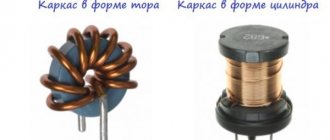
Inductor design
An inductor is a winding of conductive material, usually copper wire, wound around either an iron-containing core or no core at all.
The use of materials with high magnetic permeability, higher than air, as a core helps to retain the magnetic field near the coil, thereby increasing its inductance. Inductive coils come in different shapes and sizes.
Most are made by winding enameled copper wire over a ferrite core.
Some inductive coils have an adjustable core that allows the inductance to vary.
Miniature coils can be etched directly onto the PCB in a spiral pattern. Low-value inductors can be located in microcircuits using the same technological processes used to create transistors.
Series connection of conductors
The serial connection scheme means that they are switched on in a certain sequence, one after the other. Moreover, the current strength in all of them is equal. These elements create a total stress in the area. Charges do not accumulate in the nodes of the electrical circuit, since otherwise a change in voltage and current would be observed. With a constant voltage, the current is determined by the value of the circuit resistance, so in a series circuit, the resistance changes if one load changes.
The disadvantage of this scheme is the fact that if one element fails, the others also lose the ability to function, since the circuit is broken. An example would be a garland that does not work if one bulb burns out. This is a key difference from a parallel connection, in which the elements can operate separately.
The sequential circuit assumes that, due to the single-level connection of the conductors, their resistance is equal at any point in the network. The total resistance is equal to the sum of the voltage reduction of individual network elements.
With this type of connection, the beginning of one conductor is connected to the end of another. The key feature of the connection is that all the conductors are on one wire without branches, and one electric current flows through each of them. However, the total voltage is equal to the sum of the voltages on each. You can also look at the connection from another point of view - all conductors are replaced by one equivalent resistor, and the current on it coincides with the total current that passes through all resistors. The equivalent cumulative voltage is the sum of the voltage values across each resistor. This is how the potential difference across the resistor appears.
Watch this video on YouTube
Using a daisy chain connection is useful when you need to specifically turn a specific device on and off. For example, an electric bell can ring only when there is a connection to a voltage source and a button. The first rule states that if there is no current on at least one of the elements of the circuit, then there will be no current on the rest. Accordingly, if there is current in one conductor, it is also in the others. Another example would be a battery-powered flashlight, which only lights up if there is a battery, a working light bulb, and a button pressed.
In some cases, a sequential circuit is not practical. In an apartment where the lighting system consists of many lamps, sconces, chandeliers, there is no need to organize a scheme of this type, since there is no need to turn the lighting on and off in all rooms at the same time. For this purpose, it is better to use a parallel connection in order to be able to turn on the light in individual rooms.
Mixed connection of energy receivers
The most widespread is a mixed connection of electrical energy receivers. This connection is a combination of series and parallel connected elements. There is no general formula for calculating this type of connection, so in each individual case it is necessary to highlight sections of the circuit where there is only one type of receiver connection - serial or parallel. Then, using the formulas of equivalent resistances, gradually simplify these fates and ultimately bring them to the simplest form with one resistance, while calculating currents and voltages according to Ohm’s law. The figure below shows an example of a mixed connection of energy receivers
An example of a mixed connection of energy receivers.
As an example, let's calculate currents and voltages in all sections of the circuit. First, let's determine the equivalent resistance of the circuit. Let us select two sections with parallel connection of energy receivers. These are R1||R2 and R3||R4||R5. Then their equivalent resistance will be of the form
As a result, we obtained a circuit of two serial R12R345 energy receivers with equivalent resistance and the current flowing through them will be
Then the voltage drop across sections will be
Then the currents flowing through each energy receiver will be
1.3. SERIES CONNECTION OF ACTIVE RESISTANCE R, CAPACITOR C AND INDUCTANCE L
Let's consider a circuit with active, inductive and capacitive resistances connected in series (Fig. 1.3.1).
To analyze the circuit, let us decompose the network voltage U into three components: UR - voltage drop across active resistance, UL - voltage drop across inductive reactance, UC - voltage drop across capacitive reactance.
The current in circuit I will be common to all elements:
The check is carried out according to the formula:
It should be noted that the voltages in individual sections of the circuit are not always in phase with the current I. Thus, on an active resistance the voltage drop is in phase with the current, on an inductive one it leads the current in phase by 90° and on a capacitive one it lags behind it by 90° °. This can be shown graphically in a vector diagram (Fig. 1.3.2).
The three voltage drop vectors depicted above can be geometrically added into one (Fig. 1.3.3).
In such a connection of elements, active-inductive or active-capacitive character of the circuit load is possible. Therefore, the phase shift has both a positive and negative sign. The interesting mode is when = 0. In this case
This mode of operation of the circuit is called voltage resonance. The impedance at voltage resonance has a minimum value: , and at a given voltage U, the current I can reach its maximum value. From the condition we determine the resonant frequency
The phenomenon of voltage resonance is widely used in radio engineering and in individual industrial installations.
Inductor. Inductance formula
- L = inductance in henry
- μ 0 = permeability of free space = 4π × 10 -7 H/m
- μ g = relative permeability of core material
- N = number of turns
- A = Cross-sectional area of the coil in square meters (m2)
- l = coil length in meters (m)
- L = inductance in nH
- l = conductor length
- d = conductor diameter in the same units as l
- L = inductance in µH
- r = outer coil radius
- l = coil length
- N = number of turns
- L = inductance in µH
- r = average coil radius
- l = coil length
- N = number of turns
- d = coil depth
- L = inductance in µH
- r = average coil radius
- N = number of turns
- d = coil depth
Formula for parallel connection of resistors
The total resistance of several resistors connected in parallel is determined by the following formula:
The current flowing through a single resistor, according to Ohm's law, can be found using the formula:
Example No. 1
When developing the device, it became necessary to install a resistor with a resistance of 8 ohms. If we look at the entire nominal range of standard resistor values, we will see that there is no resistor with a resistance of 8 ohms.
The way out of this situation is to use two parallel connected resistors. The equivalent resistance value for two resistors connected in parallel is calculated as follows:
This equation shows that if R1 is equal to R2, then the resistance R is half the resistance of one of the two resistors. With R = 8 ohms, R1 and R2 must therefore have a value of 2 × 8 = 16 ohms. Now let's check by calculating the total resistance of the two resistors:
Thus, we obtained the required resistance of 8 ohms by connecting two 16 ohm resistors in parallel.
Calculation example No. 2
Find the total resistance R of three parallel connected resistors:
The total resistance R is calculated by the formula:
This calculation method can be used to calculate any number of individual resistances connected in parallel.
One important point to remember when calculating resistors connected in parallel is that the total resistance will always be less than the value of the least resistance in that combination.
How to calculate complex resistor wiring diagrams
More complex resistor connections can be calculated by systematically grouping resistors. In the figure below, you need to calculate the total resistance of a circuit consisting of three resistors:
Resistors R2 and R3 are connected in series (group 2). They, in turn, are connected in parallel with resistor R1 (group 1).
The series connection of resistors of group 2 is calculated as the sum of resistances R2 and R3:
As a result, we simplify the circuit in the form of two parallel resistors. Now the total resistance of the entire circuit can be calculated as follows:
Calculation of more complex connections of resistors can be performed using Kirchhoff's laws.
Current flowing in a circuit of parallel connected resistors
The total current I flowing in a circuit of parallel resistors is equal to the sum of the individual currents flowing in all parallel branches, and the current in a single branch does not necessarily have to be equal to the current in adjacent branches.
Despite the parallel connection, the same voltage is applied to each resistor. And since the value of resistance in a parallel circuit can be different, the amount of current flowing through each resistor will also be different (as defined by Ohm’s law).
Let's consider this using the example of two resistors connected in parallel. The current that flows through each of the resistors (I1 and I2) will be different from each other since the resistances of resistors R1 and R2 are not equal. However, we know that the current that enters the circuit at point "A" must leave the circuit at point "B".
Kirchhoff's first rule states: "The total current leaving the circuit is equal to the current entering the circuit."
- Thus, the total current flowing in the circuit can be defined as:
- I = I1 + I2
- You can then use Ohm's law to calculate the current that flows through each resistor:
- Current flowing in R1 = U ÷ R1 = 12 ÷ 22 kOhm = 0.545 mA
- Current flowing in R 2 = U ÷ R2 = 12 ÷ 47 kOhm = 0.255 mA
- Thus, the total current will be equal to:
- I = 0.545 mA + 0.255 mA = 0.8 mA
- This can also be verified using Ohm's law:
- I = U ÷ R = 12 V ÷ 15 kOhm = 0.8 mA (same)
- where 15 kOhm is the total resistance of two parallel connected resistors (22 kOhm and 47 kOhm)
- And in conclusion, I would like to note that most modern resistors are marked with colored stripes and their purpose can be found out here.
Parallel connection of resistors - online calculator
To quickly calculate the total resistance of two or more resistors connected in parallel, you can use the following online calculator:
Summarize
When two or more resistors are connected such that both terminals of one resistor are connected to the corresponding terminals of another resistor or resistors, they are said to be connected in parallel. The voltage across each resistor within a parallel combination is the same, but the currents flowing through them may differ from each other, depending on the value of the resistance of each resistor.
The equivalent or total resistance of a parallel combination will always be less than the minimum resistance of the resistor included in the parallel connection.
Unit converter
1 mH = 0.001 G. 1 μH = 0.000001 = 10⁻⁶ H. 1 nH = 0.000000001 = 10⁻⁹ H. 1 pH = 0.000000000001 = 10⁻¹² G. Learn more about inductance units.
Inductance characterizes the ability of an electrical conductor to convert electric current into a change in electrical potential in a given conductor (self-inductance) and in adjacent conductors (mutual inductance). Inductance is usually denoted by the symbol L in honor of the German-born Russian physicist Emilius Christianovich Lenz.
By definition of self-induction, voltage v(t)
and current
i(t)
in the inductor are related by the expression
All inductors connected in parallel have the same voltage V
.
According to Kirchhoff's rule for current, the total current I
is equal to the sum of the currents flowing through the individual coils:
The total inductance Leq of three inductors connected in parallel, located far from each other and not having a common magnetic field, is equal to the reciprocal of the sum of the reciprocals of their inductances:
Or for n
uncoupled inductors:
This formula for L
eq is used for calculations in this calculator. For example, the total inductance of three 10, 15 and 20 µH inductors connected in parallel would be
µH
Note that if one or more inductance values are zero, then Leq tends to zero. Imagine a very short straight conductor shunting an inductor - it will have almost zero inductance. Note also that it is impossible to create a circuit with zero inductance. If only two inductors are connected in parallel, we have:
or
Equivalent inductance n
identical inductors connected in parallel,
L
is equal to
Note that the formula for calculating the total inductance of several inductors connected in parallel is also used to calculate the resistance of a group of resistors connected in parallel.
Note also that for a group of any number of inductors connected in parallel, the equivalent inductance will always be less than the smallest inductance in the group of inductors, and adding another inductor will always reduce the equivalent inductance of the group.
Toroidal inductors in the printer power module
If the inductors are located in each other's magnetic field, these formulas will not work due to the phenomenon of mutual induction (mutual induction)
, which is covered in our mutual induction calculator. The mutual inductance effect can reduce or increase the total inductance of the coils depending on how the magnetic coupling between the coils works. The amount of mutual induction depends on the distance between the coils and their orientation. In this case, mutual inductance can increase or decrease the total inductance.
If several inductors are connected in series
, their equivalent inductance is determined by simply adding the inductances of the individual coils.
For n
inductors connected in series we have
You may have already noticed that inductors behave exactly like resistors: if the coils are connected in series, their equivalent inductances will always be higher than the inductances of the individual coils connected in series, and when connected in parallel, the equivalent inductance will always be less than the inductances of the individual coils .
Multilayer stacked helical inductor in a microcircuit and its simplified equivalent circuit
Why connect the coils in series when you can just wind a large inductor? Here is one example.
In microelectronics, to realize fairly large inductances per unit area of an integrated circuit, a combination of spiral coils in several layers of metallization is used. A multilayer stacked inductor configuration is used for this purpose. Several layers of metallization with spiral coils are placed exactly one above the other. The coils are connected in series so that the inductors add up to form one large inductor. Without such a stacked arrangement, it would be impossible to create large inductors using planar technology. Thanks to this stacked arrangement, the coil coupling coefficient k
≈ 1.
In this calculator we only consider ideal inductors. However, we live in the real world, where real coils have both resistance and capacitance. In another calculator, we will look at the characteristics of non-ideal inductors with resistance, which are described by an equivalent circuit of inductance and resistance connected in series, in particular their timing characteristics.
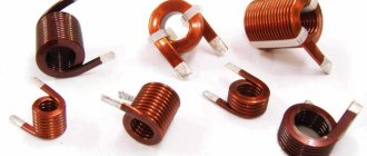
Frameless coreless inductors in RF module
Author of the article: Anatoly Zolotkov
Electrical circuits. Series and parallel connections of conductors
Details
“Physics – 10th grade”
What does the dependence of the current in a conductor on the voltage across it look like? What does the dependence of the current strength in a conductor on its resistance look like?
From a current source, energy can be transmitted through wires to devices that consume energy: an electric lamp, a radio, etc. For this, electrical circuits
of varying complexity.
The simplest and most common conductor connections include series and parallel connections.
Series connection of conductors.
With a series connection, the electrical circuit has no branches. All conductors are connected to the circuit one after another. Figure (15.5, a) shows a series connection of two conductors 1 and 2, having resistances R1 and R2. These can be two lamps, two windings of an electric motor, etc.
The current strength in both conductors is the same, i.e.
I1 = I2 = I. (15.5)
In conductors, electric charge does not accumulate in the case of direct current, and the same charge passes through any cross-section of the conductor over a certain time.
The voltage at the ends of the circuit section under consideration is the sum of the voltages on the first and second conductors:
U = U1 + U2.
Applying Ohm's law for the entire section as a whole and for sections with conductor resistances R1 and R2, it can be proven that the total resistance of the entire section of the circuit when connected in series is equal to:
R = R1 + R2. (15.6)
This rule can be applied to any number of conductors connected in series.
The voltages on the conductors and their resistances in a series connection are related by the relation
Parallel connection of conductors.
Figure (15.5, b) shows a parallel connection of two conductors 1 and 2 with resistances R1 and R2. In this case, the electric current I branches into two parts. We denote the current strength in the first and second conductors by I1 and I2.
Since at point a - the branching of the conductors (such a point is called a node) - the electric charge does not accumulate, the charge entering the node per unit time is equal to the charge leaving the node during the same time. Hence,
I = I1 + I2. (15.8)
The voltage U at the ends of conductors connected in parallel is the same, since they are connected to the same points in the circuit.
The lighting network usually maintains a voltage of 220 V. Devices that consume electrical energy are designed for this voltage. Therefore, parallel connection is the most common way to connect different consumers. In this case, the failure of one device does not affect the operation of the others, whereas with a series connection, the failure of one device opens the circuit. Applying Ohm's law for the entire section as a whole and for sections of conductors with resistances R1 and R2, it can be proven that the reciprocal of the total resistance of the section ab is equal to the sum of the reciprocals of the resistances of individual conductors:
It follows that for two conductors
The voltages on parallel-connected conductors are equal: I1R1 = I2R2. Hence,
Let us pay attention to the fact that if in some section of the circuit through which direct current flows, a capacitor is connected in parallel to one of the resistors, then the current will not flow through the capacitor, the circuit in the section with the capacitor will be open. However, between the plates of the capacitor there will be a voltage equal to the voltage across the resistor, and a charge q = CU will accumulate on the plates
Let's consider a chain of resistances R - 2R, called a matrix (Fig. 15.6).
On the last (right) link of the matrix, the voltage is divided in half due to the equality of resistances; on the previous link, the voltage is also divided in half, since it is distributed between a resistor with resistance R and two parallel resistors with resistance 2R, etc. This idea - voltage division - lies in the basis of converting binary code into direct voltage, which is necessary for the operation of computers.
Next page “Examples of solving problems on the topic “Ohm's Law. Series and parallel connections of conductors""
Back to the section “Physics – 10th grade, textbook Myakishev, Bukhovtsev, Sotsky”
Laws of direct current – Physics, textbook for grade 10 – Classroom physics
Electricity. Current strength - Ohm's Law for a section of a circuit. Resistance - Electrical circuits. Series and parallel connections of conductors - Examples of solving problems on the topic “Ohm's Law. Series and parallel connections of conductors" - Work and power of direct current - Electromotive force - Ohm's law for a complete circuit - Examples of solving problems on the topic "Work and power of direct current. Ohm's law for a complete circuit"
Capacitor in AC circuit
Direct current cannot exist in a circuit containing a capacitor. The movement of electrons is prevented by a dielectric located between the plates. But alternating current can exist in such a circuit, as evidenced by experience with a lamp (see figure below).
Even if such a circuit is actually open, but if alternating current flows through it, the capacitor is either charged or discharged. The current flowing when the capacitor is recharged heats the lamp filament, and it begins to glow.
Let's find how the current strength changes in a circuit containing only a capacitor, if the resistance of the wires and plates of the capacitor can be neglected (see figure above). The voltage across the capacitor will be equal to:
u=φ1−φ2=qC..
Let's take into account that the voltage across the capacitor is equal to the voltage at the ends of the circuit:
qC..=Umaxcos.ωt
Consequently, the charge of the capacitor changes according to the harmonic law:
q=CUmaxcos.ωt
Then the current strength, which is the time derivative of the charge, will be equal to:
i=q´=−CUmaxsin.ωt=CUmaxcos.(ωt+π2..)
Consequently, current fluctuations are ahead of voltage fluctuations across the capacitor by π2.. (see graph below). This means that at the moment when the capacitor begins to charge, the current is maximum and the voltage is zero. After the voltage reaches its maximum, the current becomes zero, etc.
The amplitude of the current is:
Imax=UmaxCω
Let's assume that:
1Cω..=XC
We will also use the effective values of current and voltage. Then we get that:
Definition
I=UXC..
The value of XC, equal to the inverse product of the cyclic frequency and the electrical capacitance of the capacitor, is called capacitance . The role of this quantity is similar to the role of active resistance R in Ohm's law.
Note that during the quarter period when the capacitor is charged to its maximum voltage, energy enters the circuit and is stored in the capacitor in the form of electric field energy. In the next quarter of the period (when the capacitor is discharged), this energy is returned to the network.
Example No. 1. The maximum charge on the capacitor plates of the oscillatory circuit is qmax=10−6 C. The amplitude value of the current in the circuit is Imax = 10−3 A. Determine the period of oscillation (neglect losses due to heating of the conductor).
According to the law of conservation of energy, the maximum value of the energy of the electric field of the capacitor is equal to the maximum value of the magnetic field of the coil:
q2max2C..=LI2max2..
From here:
LC=q2maxI2max..
√LC=qmaxImax..
T=2π√LC=2πqmaxImax..=2·3.1410−610−3..≈6.3·10−3 (s)