Phasing is the coordination of electrical phases with each other in polarity and direction of alternation when connecting. Correctly phased windings are connected in star and delta. (See Diagrams of electrical connections of neutrals of electrical machines). By phasing, in the usual sense of the word, we mean connecting a three-phase power source to a three-phase consumer, where compliance with phase rotation is fundamentally important. For example, if three-phase electric motors are connected incorrectly, they begin to rotate in the opposite direction, which leads to disruption of the technological cycle in which these electric motors are used as drives.
Direct and reverse phase rotation
Three-phase alternating current is graphically represented by three phases in the form of alternating sinusoids on the X-axis, shifted relative to each other by 120°. The first sine wave can be represented as phase A, the next sine wave as phase B, shifted 120° relative to phase A, and the third phase C, also shifted 120° relative to phase B.
Graphic display of phase shift for 120° three-phase network
If the phases have the order ABC, then this sequence of phases is called direct alternation. Consequently, the order of the SVA phases will mean reverse alternation. In total, three direct alternations of phases ABC, BCA, CAB are possible. For reverse phase rotation, the order will look like CBA, BAC, ACB.
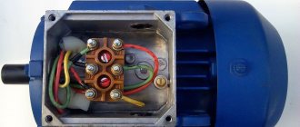
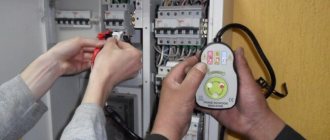
You can check the phase rotation of a three-phase network using a phase indicator FU - 2. It is a small case on which there are three clamps for connecting three phases of the network, an aluminum disk with a black dot on a white background and three windings. Its operating principle is similar to that of an asynchronous electric motor.
If you connect the phase indicator to three phases and press the button on the housing, the disk will begin to rotate in one direction. When the rotation of the disk coincides with the arrow on the body, then the phase indicator shows direct phase rotation; rotation of the disk in the opposite direction indicates reverse phase rotation.
Electrical circuit of the phase indicator FU-2
In what cases is it necessary to know the order of phase rotation? Firstly, if the house is connected to a three-phase network and an induction electric meter is installed, then direct phase rotation must be observed on it. If such an electric meter is connected incorrectly, it may self-propel, which will give incorrect readings in the direction of increasing electricity consumption.
Also, if asynchronous electric motors are used in the house, the direction of rotation of the rotor will depend on the order of phase alternation. By changing the phase sequence on an asynchronous electric motor, you can change the direction of rotation of the rotor in the desired direction.
Equipment phasing - Devices and devices used for phasing
Contents of the material
- Equipment phasing
- Basic concepts and definitions
- Devices and devices used for phasing
- Megaohmmeter
- Voltage indicator for phasing
- FK-80 device for cable phasing
- Phasing methods
- Pre-phasing
- Direct phasing methods
- Phasing at substations with a simplified diagram
- Indirect phasing methods
- Generator phasing
- Mismatch of alternations and phase designations
Voltmeters.
For phasing in electrical installations up to 1000 V, alternating current voltmeters are used, directly connected to the terminals of electrical equipment or conductive parts of devices. Great accuracy is not required from these devices, and no requirements are imposed on them regarding the principle of operation. The scale of the device must be designed for double phase or line voltage of the installation, depending on the phasing method and the type of equipment being phased. When phasing equipment with a voltage of 6 kV and higher, the voltmeter is connected to measuring voltage transformers of a stationary installation (busbar, generator). The use of portable voltage transformers with a voltmeter on the LV side is not recommended, since this is unsafe for personnel.
Phase indicator.
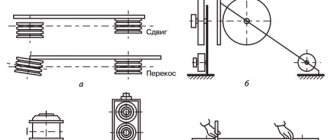
The order of the phases is checked using an induction phase indicator of type I-517 or a phase indicator of the FU-2 type, similar in design, the appearance of which is shown in Fig. 14, a. The device consists of three coils 1. 2, 3, wound on ferromagnetic cores, and a lightweight aluminum disk 4 mounted on an axis. The operation of the device is based on the same principle as the operation of an asynchronous motor. If the three coils of the device are connected to a three-phase current system, then they form a circular magnetic field rotating in space, setting the disk in motion in the direction in which it itself rotates. The direction of rotation of the magnetic field, and therefore the disk, depends solely on the order of the phases of the currents in the coils. To determine the phase order, the phase indicator is connected to the voltage system being tested. The clamps of the device are marked, i.e. marked with the letters A, B. C. If the phases of the network coincide with the markings of the device, the disk will rotate in the direction indicated by the arrow on the device casing. This rotation of the disk corresponds to the direct order of the phases of the L.V.S network (Fig. 14.6). If the phases are connected to the device in the reverse order, namely phase A to terminal A, phase C to terminal B, phase B to terminal C, then the disk will rotate in the opposite direction (Fig. 14.). Obtaining the direct order of phases from the reverse is done by changing the places of any two phases. The devices are designed to be connected to a network with a voltage of 50-500 V for a period of no more than 5 s at a voltage up to 100 V and no more than 3 s at a voltage above 100 V. The rotation of the disk begins when you press button 5. Universal devices. Universal devices have found wide application in phasing: the portable volt-ampere phase indicator VAF-85 and the universal phase indicator type E 500/2. The VAF-85 device (Fig. 15) allows you to measure current within 1 10 A, industrial frequency voltage up to 250 V, the shift angle between the voltage and current vectors, and determine the phase order. The VAF-85 device uses the M-494 magnetoelectric device as a meter. Germanium rectifiers are used to rectify alternating current. Current measurement of 1 10 A is carried out using a current collector attachment.
Rice. 13. Appearance of the VAF-85 device; vector diagram of voltages when measuring phase (b)
Rice. 14. Appearance of the phase indicator (l) and the direction of rotation of the disk in direct (b) and reverse (c) phase order
What is phasing of a three-phase network
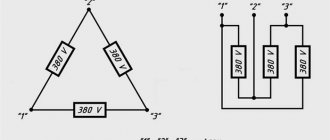
The phasing of three phases is carried out in transformer substations with parallel connection of transformers. The connection of two transformers to one three-phase network is carried out by cross-sectional circuit breakers. It is not possible to check the phases of the same name with a phase indicator.
However, you can determine the phases of the same name with a multimeter or any voltmeter with a measurement limit of 500 V. When carrying out phasing, you must follow all safety measures and check the multimeter in advance for functionality. Before finding phases of the same name, it is important to determine the presence of phase voltage relative to ground on all buses (in case of a break).
Checking for open circuit and finding phases of the same name in a three-phase network
Next, working with rubber gloves, measure the linear voltages on the buses of different transformers. If buses are found, the voltage between which is near zero, then such buses have the same phases and they are marked. Next, they find the remaining two pairs of tires of the same name and also mark them.
If the voltages between all buses of different transformers are below linear 380 V, but differ significantly from zero, then such transformers cannot be phased, since they have different connection diagrams. The found buses of the same name are connected to disconnectors for parallel operation.
The difference between phase and line voltage in a three-phase network
When the transformer has different voltages, with the same connection diagrams, they are adjusted using a tap switch of the transformer windings to the rated value. Phasing of high-voltage lines is carried out with special high-voltage indicators UVNF.
Source: electricavdome.ru
Concepts of zero and phase
How to repair a drill yourself?
Electrical energy in a residential building comes from a transformer substation, the main purpose of which is to convert high voltage, most often to 380 V. Electricity is supplied to houses underground or overhead to the input distribution board. Then the voltage is supplied to the panels of each entrance. Only one phase with zero enters the apartment from it, i.e. 220 V and protective conductor (depending on the design of the electrical wiring).
Thus, the conductor that supplies current to the consumer is called phase. Inside the transformer, the windings are connected in a star with a common point (neutral) grounded at the substation. It is connected to the load with a separate wire. The neutral, which is a common conductor, is designed to allow current to flow back to the source of electricity. In addition, the neutral wire equalizes the phase voltage, i.e. value between zero and phase.
Ground, often referred to simply as ground, is not connected to voltage. Its purpose is to protect a person from the effects of electric current at the moment of problems with the consumer, i.e. in case of breakdown on the body. This can occur when the insulation of the conductors is damaged and the damaged area of the device body touches. But since consumers are grounded, when dangerous voltage occurs on the frame, grounding attracts the dangerous potential to the safe ground potential.
Checking the phase rotation of power cables
Simple cable phasing methods
The simplest way to find current-carrying conductors at the end of a cable that correspond to certain phases of its beginning is to check the “continuity” of the cable conductors using telephone handsets, for example, when checking power cables laid between different rooms of stations and substations. The connection diagram for telephone handsets is shown in Figure 1.
As one of the wires for establishing communication, grounded structures (grounded metal sheath of the cable) are used, to which telephone handsets are connected. Next, on one side of the cable, the wire from the battery is connected to a current-carrying core (for example, phase C).
Diagram for connecting telephone handsets with cable phasing
On the other side of the cable, the second wire from the handset touches the current-carrying wires one by one, each time sending a voice signal into the handset. Having found a vein for which the inspector's review will be received, it is marked as phase C and the search for other veins continues in the same order. Instead of ordinary telephone handsets, it is advisable to use telephone headsets, the use of which frees up the hands of inspectors for work.
To check phase rotation, a megohmmeter is widely used, the connection diagram of which is shown in Figure 2. To do this, the conductors at the beginning of the cable are grounded one by one, and at the end the insulation resistance of the conductors relative to the ground is measured.
Megger connection diagram for cable phasing
A grounded conductor is detected by the readings of a megohmmeter, since the resistance of its insulation to the ground will be zero, and the other two conductors will be tens or even hundreds of megaohms.
With this test method, ground connections are installed and removed three times. In addition, personnel located at the ends of the cable must communicate with each other in order to coordinate their actions. All this refers to the disadvantages of this method of verification.
A more advanced method of cable phasing is the measurement method according to the diagram shown in Figure 3.
One of the three cable cores (let's call it phase A) is rigidly connected to a grounded shell, the other core (phase C) is grounded through a resistance of 8-10 MOhm. A tube with UVNF indicator resistors is usually used as a resistance. The third core (phase B) is not grounded; it remains free. At the other end of the cable, the resistance of the conductors relative to the ground is measured with a megohmmeter.
Obviously, phase A will correspond to a conductor whose resistance to ground is zero, phase C will correspond to a conductor having a resistance to ground of 8 - 10 MOhm, and phase B will correspond to a conductor with infinitely high resistance.
Connection diagram for a megohmmeter and an additional resistor when phasing the cable
Safety precautions when producing cable phasing
According to safety conditions when phasing cables, phasing is performed only on a cable line that is disconnected on all sides. In this case, measures must be taken to prevent the supply of operating voltage to the cable. Before starting phasing using a megohmmeter, all personnel located near the cable are warned not to touch live conductors.
The connecting wires from the megohmmeter must have reinforced insulation (for example, PVL type wire). They are connected to the current-carrying conductors after the cable has been discharged from the capacitive current. To remove the residual charge, the cable is grounded for 2-3 minutes.
Checking the phase rotation of power cables based on the color of the core insulation
The current-carrying conductors of power cables with insulation made of impregnated paper are colored with ribbons of colored paper wound around their insulation. One of the cores, as a rule, is surrounded with red tape, the other with blue, and the insulation of the third is not specially colored - it retains the color of the cable paper.
Checking the phasing of cable cores at low prices in Moscow, checking the phasing of three-phase voltage
The electrical measurement laboratory LabTestEnergo provides specialized services in the field of testing and inspection of electrical equipment using modern technical means. We invite companies from Moscow and the Moscow region to cooperate and offer high quality and affordable services.
Why is it necessary to check the phasing of cable cores and how is it carried out?
During long-term operation or under the influence of mechanical factors, ruptures occur in cable lines, damage to the integrity of the insulating sheath, and damage to metal parts by corrosion, which is fraught with serious consequences. To prevent this and promptly identify problems, it is necessary to regularly check the integrity and phasing of the cable cores. Tests are carried out in accordance with established rules and methods (PUE, PTEEP).
A short introduction
A story about the installation of electrical equipment, namely two oil transformers, caught my eye. The work was completed successfully. As a result, there was the following power supply scheme. Actually the transformers themselves, input switches, sectional disconnectors, two bus sections. According to the installers, the commissioning work was completed successfully. They started switching on both transformers for parallel operation and got a short circuit. Naturally, the installers claimed that they had checked the phase rotation from both sources and everything matched. But not a word was said about phasing. But in vain! Now let's take a closer look at what went wrong.
Alternation indicator tests
The layout according to the diagram was tested on a universal board. Works without problems. The total cost of the radio components was about 200 rubles (you must admit that you cannot buy a ready-made, high-quality phase rotation indicator for this money).
When performing installation, be sure to make jumpers with well-insulated wire (such as Teflon) and consider coating the board with insulating varnish. Be sure to place everything in a plastic case. Despite the described actions, we are still dealing with high voltage three-phase networks and must be very careful! For a phase voltage of 220 V, the peak value is 320 V, and for a phase-to-phase voltage of 400 V, the peak value is 560 V, respectively.
What is phase alternation?
As you know, in a three-phase network there are three opposite phases. Conventionally, they are designated as A, B and C. Remembering the theory, we can say that the phase sinusoids are shifted relative to each other by 120 degrees. So, there can be six different alternation orders in total, and they are all divided into two types - direct and reverse. The following order is considered direct alternation - ABC, BCA and CAB. The reverse order will be CBA, BAC and DIA, respectively.
To check the order of phase alternation, you can use a device such as a phase indicator. We have already talked about how to use the phase indicator. Let's look specifically at the sequence of checking with the FU 2 device.
What is needed to check the phases
The phase indicator (see figure below) consists of three windings and a disk, which will rotate during testing. To make it easier to recognize the result, black and white marks are applied to the disc. The FU works in the same way as an asynchronous motor.
If we connect three wires to the terminals, we will see that the disk will begin to rotate. If it rotates clockwise, this means direct phase alternation (ABC, BCA or CAB). If the disk rotates counterclockwise, this means reverse phase alternation (CBA, BAC or ACB).
Let's return to our story with the electricians; they checked the phase rotation, which coincided in one and the other case. It was necessary to perform phasing, and here we could not do without a phase indicator (PI). Electricians connected opposite phases at startup, and in order to find out exactly where A, B and C were, they had to use a multimeter or oscilloscope.
The multimeter device measures the voltage between the phases of different power sources; reaching zero means that the phases are the same. Otherwise, line voltage will mean that the phases are opposite. This method is the fastest and easiest, but you can also use an oscilloscope, which will show which phase lags behind the other by 120˚.
How to check?
The device itself (shown in the photo below) consists of three windings and a disk that rotates during testing. It has black marks that alternate with white ones. This is done for ease of reading the result. The device operates on the principle of an asynchronous motor.
So, we connect three wires from a three-phase voltage source to the device terminals. Press the button on the device, which is located on the side wall. We will see that the disk begins to rotate. If it rotates in the direction of the arrow drawn on the device, it means that the phase sequence is direct and corresponds to one of the order options ABC, BCA or CAB. When the disk rotates in the opposite direction of the arrow, we can talk about reverse alternation. In this case, one of these three options is possible - CBA, BAC or DIA.
If we return to the story with the installers, then all they did was just determine the sequence of phases. Yes, in both cases the order was the same. However, it was still necessary to check the phasing. And it cannot be done using a phase indicator. When turned on, opposite phases were connected. To find out where A, B and C are conditionally, you had to use a multimeter or oscilloscope.
A multimeter measures the voltage between the phases of different power sources and if it is zero, then the phases are the same. If the voltage corresponds to the linear voltage, then they are different. This is the simplest and most effective way. You can find out more about how to use a multimeter in our article. You can, of course, use an oscilloscope and look at the oscillogram which phase lags behind which by 120 degrees, but this is impractical. Firstly, this makes the technique an order of magnitude more complicated, and secondly, such a device costs a lot of money.
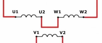
How to determine the beginning and end of a winding in a motor.
In this article I will tell you a way to determine the beginning and end of the winding in an asynchronous three-phase motor.
When might you need this material? Only if you have six wires of the same color in the box and there are no markings on them. Or your motor was connected in delta and you want to be able to connect it in star. I wrote how to do this here. To make it easier to explain the material, let’s first go through the accepted markings of motor winding terminals.
Conclusions of an asynchronous motor. Marking of asynchronous motor terminals
There are various markings for the terminals of the motor windings. Domestic markings from C1 to C6 and international, which you see in the figure.
Nowadays, both markings are found, but for “training” we will use new designations as they are more descriptive. Earlier, I already said that the beginning and end of the windings are absolutely conditional concepts, the main condition that plays an important role is such a connection of the windings when the magnetic fluxes are not directed in the opposite direction. If two identical flows are sent counter, they seem to destroy each other. We need to obtain a consistent direction of magnetic fluxes. The motor has three windings. Roughly speaking, a motor is a transformer with three windings and a stator core. Thus, the windings in the motor are connected by a magnetic flux that flows through the stator, and it is created by a current that flows through the windings. The rotor is just a pleasant “yummy”, the presence of which allows you to convert electrical energy into mechanical energy.
When should order be considered?
It is necessary to check the phase rotation when operating three-phase AC motors. The order of the phases will change the direction of rotation of the motor, which is sometimes very important, especially if there are many mechanisms on the site that use motors.
It is also important to take into account the order of the phases when connecting a CA4 induction type electric meter. If the order is reversed, a phenomenon such as spontaneous movement of the disk on the counter is possible. New electronic meters, of course, are insensitive to phase rotation, but a corresponding image will appear on their indicator.
If you have an electrical power cable with which you need to connect a three-phase power supply, and you need phasing control, it can be done without special devices. Often the cores inside the cable differ in the color of the insulation, which greatly simplifies the “dialing” process. So, to find out where phase A, B or C is conventionally located, you only need to remove the outer insulation of the cable. At both ends we will see veins of the same color. We will accept them as the same. You can learn more about color coding of wires from our article.
But still, you cannot blindly trust such markings. So, in practice, there are cases that cable manufacturers cannot guarantee that the color of the cores at the beginning and end of the cable will be the same. Therefore, you still need to ring the wires with a ringer.
Now you know what phase rotation is in a three-phase network and how to check it using instruments. We hope the information was useful and interesting for you!
We also recommend reading:
Source: samelectrik.ru
How to calculate phasing of an electric line - All about electricity
Phasing is the coordination of electrical phases with each other in polarity and direction of alternation when connecting. Correctly phased windings are connected in star and delta. (See Diagrams of electrical connections of neutrals of electrical machines).
By phasing, in the usual sense of the word, we mean connecting a three-phase power source to a three-phase consumer, where compliance with phase rotation is fundamentally important. For example, if three-phase electric motors are connected incorrectly, they begin to rotate in the opposite direction, which leads to disruption of the technological cycle in which these electric motors are used as drives
For example, if three-phase electric motors are connected incorrectly, they begin to rotate in the opposite direction, which leads to disruption of the technological cycle in which these electric motors are used as drives.
Direct phasing of the electrical line: what is it and 2 connection options
To phase an electric line, you need to have the appropriate experience and knowledge. A phase meter or, in other words, a phase indicator will help you phase a generator or electric motor. However, it is not easy to find in stores or there is simply no point in buying it for one-time use.
For cable wires, it is imperative to know the input phases, otherwise a short circuit may occur. If the definition is correct, it will be much more convenient to calculate the voltage.
What is phasing, and how to determine the phases, how to use a multimeter and make such a device at home - about all the nuances below.
Phasing or phasing is a clarification of the similarity of the phases under current of each of the 3 lines. The phased windings are coordinated, which ensures the correct operation of different electrical devices.
Currently, you can do this yourself.
Nuances:
Phasing affects the direction of rotation of the motor, which is a very important condition, especially if several mechanisms use motors of the same order. Another case where you definitely need to pay attention to phase rotation is when using an induction-type electric meter. In the reverse order, spontaneous rotation of the disk located on the counter often occurs
These meters are currently less demanding in terms of phasing, but the corresponding data also appears on the indicator. In some cases, monitoring the phase arrangement can be performed without the use of special instruments. For example, if a three-phase power supply is connected when connecting power cables. If the cores inside this cable are different in color, then the continuity occurs many times faster. In some cases, you just need to peel off the outer insulation of the cable to find out which phase is which. Wires of the same color indicate that the phases are the same.
Phase rotation is checked using a special device
However, color marking does not always guarantee the correct arrangement of phases, because not all manufacturers adhere to such standards. Sometimes you can find different colors at different ends of the cable, so the ideal and most reliable way to determine which phase is which is to use core continuity tests.
The versatility of the phase detector
The mechanism for calculating the phasing sequence, that is, the determinant, is best suited for this. It is designed to detect phasing, in which the voltage lags behind the value in phase. The point of this lag taken as a starting point is needed to correctly connect to the network devices that require compliance with the phase sequence. One example of such a device could be a three-phase four-wire electric meter.
The design of such a device is simple:
- The base is an electrical insulating material, for example, textolite.
- It contains 2 wall-mounted electric sockets, inside of which there are ordinary incandescent lamps, covered with translucent casings.
- On their basis, the capacitor and the terminal block for connecting the wires are strengthened.
Checking the phasing of electrical equipment
Three-phase electrical equipment (transformers, generators, cable power lines) is subject to mandatory phasing before it is first connected to the network or after the completion of the next repair, as a result of which a violation of the sequence of phases could occur.
Phasing consists of checking the phase coincidence of the voltages of each of the 3 phases of the electrical installation being switched on with the corresponding network voltages. This kind of check is certainly necessary, because during the assembly, installation and repair of electrical equipment, the phases could be rearranged.
In electric machines, for example, it is not excluded that the power terminals of the stator windings are incorrectly designated; Cables in connecting couplings can have conductors of opposite phases connected to each other.
In all these cases, the only way out is to perform phasing. As a rule, this technological operation consists of 3 main stages listed below.
Checking and comparing the phase sequence of an electrical installation and network
. This operation is performed before directly switching on parallel operation of several networks operating independently, a new generator and a generator that has undergone a major overhaul, during which the connection diagram of the stator windings to the network may have changed.
Only when positive results obtained from phasing are obtained, generators or, say, transformers are synchronized and switched on for parallel operation.
Checking the identity or color of phase conductors
, which will subsequently need to be connected. This operation aims to check the correct connection of all installation elements to each other. Simply put, the correctness of the supply of current-carrying conductors to the switching device is verified.
Checking the phase coincidence of voltages of the same name
, that is, the absence of a phase shift angle between them. In electrical networks, when phasing power lines and power transformers that belong to the same electrical system, it is enough to perform the last 2 operations, since all generators operating synchronously with the network have the same phase order.
Phasing devices
. Today there are many techniques that depend on the intended purpose of the electrical equipment, the winding connection diagrams and the devices and devices used. The main instruments and devices include:
AC Voltmeters
, used for phasing electrical installations up to 1 kV and connected directly to the terminals of electrical equipment.
Phase indicators
, the principle of operation of which is similar to the principle of operation of an IM (asynchronous motor), when when a coil of devices is connected to a 3-phase current network, a rotating magnetic field is formed, which causes the working disk to rotate. In this case, by the direction of rotation of the disk, one can judge the correct order of the phases of the currents passing through the coils.
Universal devices (portable volt-ampere phase indicators, universal phase indicators)
.
Megaohmmeters
, which are portable devices necessary for measuring insulation resistance in wide ranges, which have proven themselves very well in the production of phasing.
Voltage indicators
for phasing. These devices are well suited for phasing electrical installations above 1 kV. When performing an operation on a disconnected device (disconnector, circuit breaker), phased voltages are supplied to each side.
At the same time, the probes of the device are brought to the current-carrying parts of the phased device, and then the glow of the signal lamp on the device is monitored.
It is worth considering that the burning of the lamp indicates a phase mismatch, and the absence of the light of the lamp indicates consistent switching on and the possibility of switching on the switching device.
Phasing methods
. This operation may be preliminary; performed during installation and repair of electrical equipment, and phasing immediately before commissioning, carried out before the first switching on of the equipment, when the phases could be swapped.
Source: forum220.ru
LLC "EnergoAlliance"
ELECTRICAL LABORATORY
1. INTRODUCTORY PART
1.1. This document establishes the methodology for phasing reactor plants and their connections.1.2. Scope and use.1.2.1. Switchgears, electrical equipment.
2. PHASING METHODS
2.1. Phasing can be preliminary, performed during the installation and repair of equipment, and during commissioning, carried out immediately before the first start-up of new or repaired equipment, if the phases could have been swapped during the repair.
2.2. Preliminary phasing checks the phase sequence of interconnected equipment elements. So, for example, when repairing a damaged cable, it is determined which cores of the cable that was in operation and the repair insert must be connected to each other so that the phases of the cable line and the switchgear busbars coincide. Therefore, before connecting the cores, their phasing is checked. Preliminary phasing is carried out on equipment that is not under voltage. The main types of equipment are phased visually, by “diagnosis”, using a megger or pulse finder.
2.3. Regardless of whether preliminary phasing of the equipment was carried out or not during its installation or repair, it must be phased when put into operation, since only in this case can one be sure of the phase consistency of all elements of the electrical circuit. Phasing during commissioning is carried out exclusively by electrical methods. The choice of method depends on the type of phased equipment (generator, transformer, line) and the voltage class at which it must be put into operation.
2.4. There are direct and indirect methods for phasing equipment during commissioning.
2.5. Direct methods are those in which phasing is performed at the inputs of equipment that is directly under operating voltage; These methods are intuitive and widely used in installations up to 330 kV.
2.6. Indirect methods are those in which phasing is carried out not at the operating voltage of the installation, but at the secondary voltage of voltage transformers connected to the phased parts of the installation.
2.7. Phasing consists of three operations:
2.7.1 The first consists of checking and comparing the order of phase rotation of the electrical installation and network being put into operation.
2.7.2. The second is to check the phase coincidence of voltages of the same name (the absence of an angular shift between them).
2.7.3. The third is to check the identity (color) of the phases that are supposed to be connected, in order to check the correct connection of current-carrying parts to the switching device.
2.8. To check phase coincidence using the direct method in electrical installations up to 1000 V, AC voltmeters are used, connected directly to the terminals of electrical equipment or to live parts of switching devices.
2.9. The measuring range of the device must be designed for double phase or double line voltage of the installation, depending on the phasing method and the type of phased equipment.
2.10. When phasing equipment with a voltage of 6 kV and the above-indirect method, the voltmeter is connected to the secondary windings of permanently installed measuring voltage transformers. The use of portable voltage transformers is not permitted.
2.11. To check phase coincidence using the direct method in electrical installations above 1000 V, voltage indicators are used. In this case, phased voltages are supplied to the disconnected switching device on both sides. The indicator probes are used to touch the current-carrying parts of the device and control the glow of the indicator lamp.
3. MEASURING INSTRUMENTS, AUXILIARY DEVICES, MATERIALS
3.1. Multimeter;
3.2. Megaohmmeter E6-24, E6-31;
3.3. Mobile electrical laboratory ETL-35K;
3.4. High voltage indicator UVNF.
4. SAFETY REQUIREMENTS, ENVIRONMENTAL PROTECTION
4.1. Phasing is carried out by personnel of at least two people, one of whom has electrical safety group IV, and the second not lower than III, when working in electrical installations above 1000 V.
4.2. Safety conditions for phasing with voltage indicators. Before proceeding with phasing, it is necessary to ensure that both the general safety requirements for preparing the workplace and the special requirements for working with measuring rods on live equipment are met.
4.3. Electrical devices at the terminals of which phasing will be performed must be securely locked even before voltage is applied to them, and measures must also be taken to prevent them from being turned on.
4.4. Before starting work under voltage, voltage indicators must be subjected to a thorough external inspection, and attention is paid to ensuring that the varnish of the tubes and the insulation of the connecting wire do not have visible damage or scratches. The shelf life of the indicator is checked using a periodic test stamp. It is not allowed to use indicators whose expiration date has expired.
4.5. When working with a voltage indicator, it is mandatory to use dielectric gloves. During phasing, it is not recommended to bring the connecting wire closer to grounded parts. The working and insulating parts of the indicator should be positioned so that there is no danger of overlap on their surface between phases or to the ground.
4.6. Phasing with a voltage indicator cannot be done during rain, snowfall, or fog, since its insulating parts may become moist, which will lead to their overlap.
5. DIRECT PHASING METHODS
5.1. Phasing of transformers with LV windings up to 380V, without installing a jumper between the terminals.
5.1.1. This method is used to phase power transformers, the secondary windings of which are connected in a star with an output zero point, as well as voltage measuring transformers with secondary windings with a grounded neutral.
5.1.2. Phasing is carried out using a voltmeter on the LV winding side. The voltmeter must be designed for double phase voltage, since the appearance of such voltage between the terminals of phased transformers is not excluded.
5.1.3. Phased transformers are switched on according to the circuit shown in Fig. 1. The neutral points of the secondary windings must be reliably grounded or connected to a common neutral wire, which should be checked before starting phasing. Combining the zero points is necessary to create an electrical connection between the phased transformers, forming a closed loop for the passage of current through the device.
5.1.4. Before proceeding with phasing, check the symmetry of the transformer voltages. To do this, the voltmeter is alternately connected to terminals al-bl, bl-cl, cl-al, a2-b2, b2-c2, c2-a2. If the values of the measured voltages differ greatly from each other, check the position of the tap switches of both transformers.
5.1.5. Switching branches reduces the voltage difference. Phasing is allowed if the voltage difference does not exceed 10%.
Rice. 1. Phasing diagram of two transformers with grounded neutral points of the secondary windings (the dashed line shows the path of current through the device in case of phase mismatch)
5.1.6. After carrying out the above operations, phasing begins. Its essence lies in finding terminals between which the voltage difference is almost close to zero.
5.1.7. To do this, the wire from the voltmeter is connected to one terminal of the first transformer, and the other wire alternately touches the three terminals of the second transformer (for example, measure the voltage between terminals a1-a2; a1 - b2; a1 - c2).
5.1.8. The further course of phasing depends on the results obtained. If during one measurement (for example, between terminals a1-a2) the voltmeter reading was close to zero, then these terminals are noticed, and the voltmeter is connected to the second terminal (for example, b1) of the first transformer and the voltage between terminals b1-b2 is measured; b1-c2. If again one of the voltmeter readings (for example, between terminals b1-b2) turns out to be close to zero, then the phasing is considered complete (Fig. 2, a). However, to confirm the results obtained about the phase coincidence, a measurement is still made between c1-c2
5.1.9. The terminals between which there was no voltage difference are connected when the transformers are switched on for parallel operation. At each pole of the switching device, such terminals must be located directly opposite each other
Rice. 2. Vector diagrams of the voltages of the LV windings of phased transformers when the phases coincide (a) and when the vectors are shifted by 180°, for example, with connection groups ∆YH-11 and ∆/YH-5 (b)
5.1.10. If after measurement (a1-a2; a1-b2; a1-c2; b1-a2; b1-b2; b1-c2 none of the voltmeter readings was close to zero, then this indicates that the phased transformers belong to different groups of connections and their inclusion in parallel operation is unacceptable.
5.1.11. Phasing is stopped at this point. Based on the measurements, vector diagrams are constructed and they are used to judge whether transformers can be connected in parallel and what reconnections need to be made for this.
5.1.12. The technique for constructing vector diagrams based on the results of linear voltage measurements is shown in Fig. 2, b. The linear voltage triangle of the first transformer is constructed arbitrarily, and the vertex points of the second triangle are found by notching, the radii of which are numerically equal to the voltages between the terminals a1-a2; b1-a2; a1-b2; b1-b2.5.2. Phasing of cable and overhead lines 6-110 kV.
5.2.1. When phasing lines with a voltage of 6-10 kV, indicators are used, for example, such as UVN-80, UVNF, etc. Phasing is performed in the following sequence.
5.2.2. Phased voltages are supplied to the terminals of the disconnectors or switch (Fig. 3). Check the serviceability of the indicator. To do this, the probe of the tube containing the resistor is touched to ground, and the probe of the other tube is brought to one of the clamps of the device under voltage (Fig. 3, a), and the neon lamp should light up.
5.2.3. Then the probes of both tubes touch one conductive part (Fig. 3, b). The indicator lamp should not light up.
5.2.4. Check the voltage at all six terminals of the switching device, as shown in Fig. 3, c.
5.2.5. The check is carried out in order to exclude an error in the event of phasing of a line that has a break (for example, due to a faulty fuse). The absolute values of the voltage between the phase and the ground do not play a role here, since during phasing the indicator will be connected either to the line voltage (phase mismatch) or to a slight voltage difference between the same phases (phase coincidence). Therefore, the presence of voltage in each phase is judged simply by the glow of the indicator lamp.
Rice. 3. Sequence of operations when phasing 10 kV lines with an indicator of the UVNF type: a - checking the serviceability of the indicator when switched on oppositely; b - the same with agreed; c - checking the presence of voltage at the terminals; g - phasing
5.2.6. The process of phasing itself consists in the fact that the probe of one indicator tube touches any extreme terminal of the device, for example, phase C, and the probe of the other tube touches alternately three terminals from the side of the phasing line (Fig. 3, d). In two cases of touch (C-A1 and C-B2) the lamp will light up brightly, in the third (C-C1) it will not light up, which will indicate the same phases.
5.2.7. After identifying the first pair of pins of the same name, the probes alternately touch other pairs of pins, for example, A-A1 and A-B1. The absence of the indicator lamp lighting in one touch will indicate that the next pair of pins is identical. The phase coincidence of the third pair of terminals B-B1 is checked only for control purposes - the phases must match.
5.2.8. Phases of the same name are connected for parallel operation. If the phases of the same name on the disconnectors or switch are not opposite each other, then the voltage is removed from the installation and the busbars are reconnected in the order necessary for the phases to match.
5.3. Phasing of overhead and cable lines using the direct method at voltages of 35 and 110 kV.
5.3.1. For this purpose, an indicator of the UVNF-35-110 type is used, the design of which is similar to the UVNF indicator at 10 kV. It is distinguished from the latter by the presence of polystyrene capacitors in the circuit instead of a resistor.
5.3.2. Phasing is carried out on disconnected disconnectors (or separators), the terminals of which are energized: on one side from the switchgear buses, on the other from the line being phased.
5.3.3. First, on all phases of the disconnectors, the presence of voltage is checked by touching the indicator probes to the phase and to the grounded structure, then on the extreme phases of the disconnectors, the coincidence of voltages in phase is checked (Fig. 4). In the middle phase, no check is carried out.
5.3.4. If the indicator lamp does not light up during phasing at the extreme phases, then the phasing is considered complete - the phases coincide. 5.3.5. When the indicator lamp lights up on both extreme phases or only on one, the phasing is stopped - the phases do not coincide.
Rice. 4. Connecting the indicator to the terminals of disconnectors when phasing 35-110 kV lines
6. INDIRECT PHASING METHODS
6.1. Phasing of transformers and lines with a double bus system.
6.1.1. This method is used to phase transformers and lines of all voltage classes. In a switchgear, where both bus systems are in operation, one bus system is released to perform phasing, i.e. put her in reserve.
6.1.2. When the bus coupling switch is turned on, use a voltmeter to check the phase coincidence of the secondary voltages of the voltage transformers of the working and backup bus systems.
6.1.3. Then the bus coupling switch is turned off and the operating current is removed from its drive. A circuit is connected to the backup bus system, the phasing of which should be done (Fig. 5).
6.1.4. Voltage is applied through the phased circuit from the opposite end and phasing is performed at the terminals of the secondary circuits of the voltage transformers of the working and backup bus systems. To do this, six measurements are made with a voltmeter in the following sequence: a1-a2; a1-b2; a1- c2; b1-a2; b1-b2; b1-c2. When phases a1 and a2, b1 and b
2, c1 and c2 (zero voltmeter readings), the phasing is completed and by turning on the bus connecting switch, the protection on which should be in the “Off” position, the phased circuit is switched on for parallel operation.
6.1.5. If, when measuring the voltage between the same terminals, results other than zero are obtained, then the measurements are stopped, the phased circuit is disconnected and the conductive parts are reconnected, achieving phase coincidence.
6.1.6. After this, phasing is performed again.
6.2. Phasing of three-winding transformers.
6.2.1. Phasing is performed in two steps: from the LV winding side and from the MV side.
6.2.2. First, the transformer is switched on to the backup LV bus system and voltage is supplied to it from the HV side. Phasing is performed at the terminals of voltage transformers belonging to LV busbars. If the phases coincide, the transformer is disconnected from the LV side, switched on to the backup MV bus system and phasing is performed at this voltage. After receiving positive results in both cases of phasing, the transformer is considered to be in phase and is put into operation.
6.2.3. When phasing electrical circuits using the indirect method, it is very important that the bus voltage transformers are first correctly phased.
Rice. 5. Indirect phasing scheme at the terminals of the secondary windings of bus voltage transformers
6.2.4. When phasing bus voltage transformers, one should take into account the grounding circuit of the secondary windings of the voltage transformers, since both the neutral and one phase can be grounded.
6.2.5. In the first case, for phasing it is possible to use a voltmeter with a scale for double phase voltage, in the second - double linear. In addition, phasing of voltage transformers in which the phase of the secondary windings is grounded (for example, phase b) is often performed using a phase indicator. This is considered acceptable, since phases B of the phased voltages are rigidly connected and it is only necessary to establish the coincidence of the voltages of the same phases a, as well as phases c. If they do not match, the phase indicator disk will rotate in one direction when voltage is applied to its terminals from the first voltage transformer, and in the other direction when voltage is applied from the second voltage transformer.
6.2.6. In no other cases of phasing three-phase circuits can you use only a phase indicator, since with the same direction of rotation of the phase indicator disk, there can be an angular shift between the voltage phases of the same name, even with the same phase order.
6.2.7. Voltage transformers of the same voltage class should be phased when powered from the same source. For example, if it is necessary to check the phase coincidence of two bus voltage transformers connected from the HV side to different bus systems (or sections), then for this the buses are connected to each other by turning on a bus coupling (or sectional) switch and then the phasing of these voltage transformers is carried out from their secondary side windings
7. DISCOVERY IN THE ORDER OF ALTERNATING AND PHASE DESIGNATION OF ELECTRICAL INSTALLATIONS DURING THEIR PHASING
7.1. At the beginning, phasing establishes a coincidence: the order of the phases of electrical installations phased together, the vectors of voltages of the same name in phase (the absence of an angular shift between them), the order of phase alternation at the terminals of the switching device, by turning on which the installation must be put into operation, the designations of the phases (their colors).
7.2. Fulfillment of the listed conditions is mandatory when putting electrical installations into operation.
7.3. In order for the phase orders of electrical installations to coincide, for example, the reverse order of the phases of one electrical installation in relation to another becomes direct, the phase order on the power transmission line is changed. In practice, this is carried out by moving the phase wires on the same support along the line, i.e., changing their alternation in space.
7.4. Thus, by changing the order of phase alternation on the line, the order of the phases of the voltage vectors of one electrical installation relative to another changes, although the absolute orders of the phases of the voltage vectors of the electrical installations remain the same (direct and reverse). This reveals the interdependence of the concepts of sequence order and phase alternation.
Rice. 6. Changing the order of phase alternation on a line when two electrical installations with direct and reverse phase order are switched on for parallel operation
7.5. In Fig. Figure 6 shows this interdependence and shows a combined vector diagram of the voltages of both phase orders. From the diagram it can be seen that the voltage vectors UA1 and UA2 are in phase and that no movements of the wire of phase A are required, but the wires of phases B and C must be swapped.
7.6. After moving the wires along the lines, the electrical installation can be phased and synchronized for parallel operation. The designations of the phases and their colors in each section of the line (dash-dotted line /-/ in Fig. 6) and on the terminals of the switching device will not match and cannot be changed in any way. The personnel serving them should know about these features of the line connecting electrical installations in order to avoid errors during operation and repair.
7.7. The same is done when phasing electrical installations that operate with vectors of the same voltages shifted by 120 and 240°. The necessary change in the order of phase alternation on the line is established by constructing and combining vector voltage diagrams of both phased electrical installations
8. PROCESSING AND CONTROL OF MEASUREMENT RESULTS
8.1. When performing phasing, the team leader must check the accuracy of the operator’s reading from the device indicators.
9. REGISTRATION OF PHASING RESULTS
9.1. The preparation of the phasing protocol is carried out by one of the team members on the instructions of the manager, who checks the completeness and accuracy of the registration of measurement results (test report).
9.2. After checking the documentation of the phasing results, the head of the measurement team allows the operators who carried out the measurements to sign the protocol (and test program).
9.3. The team leader signs the protocol and certifies the signatures with the ETL seal and registers these documents in the established manner.
Electrolaboratory Krasnodar. Electrolaboratory Krasnodar region
What is phase rotation?
Phase alternation should be understood as the sequence in which the voltage increases in each of them. In all three-phase circuits, the voltage is a sinusoidal curve. In each line the voltage differs by 120º from the others.
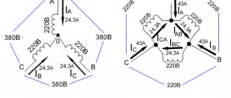
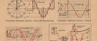
Rice. 1. Voltage in three-phase network
As you can see, in Figure 1, where a) shows the voltage curves in all phase wires, shifted by 120º. The adjacent figure b) shows a vector diagram of these voltages. Both figures show the difference between phase and line voltage.
If we take as a basis that UA comes out from the zero point in figure a), then this phase is the first; in diagram b), the arrows clearly show that the order of voltage increase goes from UA to UB, and then to UC. This means that the phases alternate in the order A, B, C. This order of alternation is considered direct.
Direct and reverse phase rotation
In a three-phase network, the order of phase rotation may differ depending on the connection methods to power transformers at substations, the sequence of switching on the generator windings, due to mismatch of cable terminals and other reasons.
How to determine the phase rotation of a three-phase electric motor: basic techniques
If we conventionally designate opposite phases in any three-phase network (the displacement of sinusoids for them is 120°) as A, B and C, then we can distinguish the following options for the order of alternation:
- straight lines (CAB, BCA, ABC);
- reverse (ACB, BAC, CBA).
By connecting equipment to a three-phase network using a power cable, the phase order can be checked without the use of special instruments. In this case, they are guided by the color (or digital) marking of the insulation of the electrical wire cores. It should be noted that in practice, insulation marking may be an insufficient criterion, since not all manufacturers guarantee that the color of the core insulation at the beginning and end of the cable will match.
Such an accessible and uncomplicated method of “dialing” the cores as using two telephone handsets allows you to achieve more reliable results. One of the handsets is “active” (equipped with a battery), the other is “passive”, without power. There is a paired headset equipped with headphones and clips specifically for phasing.
You can also use a megger. At the same time, strict compliance with safety measures is mandatory for personnel.
Why do you need to consider phase order?
The sequence of alternations plays a significant role in such situations:
- When connected in parallel, a number of devices (transformers, generators and other electrical machines) can be connected in parallel operation to increase the reliability of the system or to provide a greater power reserve. But, in case of incorrect connection, a short circuit will occur due to the connection of opposite phases.
- When connecting a three-phase meter - since its operation is based on the coincidence of phases with the corresponding terminals of the device, then if the connection is not correct, a failure and spontaneous movement may occur in the absence of any load. Because of this, such a connection of the electric meter will lead to the need for the consumer to pay for kilowatts that he did not consume.
- When the engine is turned on, the sequence of phases in the network determines the direction of rotation of the engine for the electric machine. In the absence of correct phasing, the direction of movement of the elements mechanically connected to the rotor will also change. This could result in a disruption of the technological process or a threat to the lives of personnel.
In order to prevent negative consequences from phase imbalance and other mismatches, in practice, they check the alternation and install protection.
Device for determining the phase sequence in a three-phase network
So, the above-mentioned “Device for determining the phase sequence” is designed to determine the phase in which the voltage lags behind the voltage in the phase arbitrarily taken as the starting point. Knowledge of this lag is necessary for the correct connection to the network of devices in which the phase sequence must be observed, for example, three-phase four-wire (with zero) electricity meters.
The design of the device is quite simple (Fig. 1). On a base made of electrical insulating material, such as textolite, there are two wall-mounted electric sockets with conventional incandescent lighting lamps screwed into them, covered with transparent casings made from plastic containers for juices, water, etc. A capacitor and terminals for connecting wires are also fixed on the base.
Some terminals from the lamps and the capacitor are soldered (point O), the other ends of the wires are connected to terminals A, B and C (Fig. 2).
The principle of operation of the “Device for determining the phase sequence” is as follows. When connecting the “Device...” to a three-phase network, due to the presence of a capacitor in each phase, the voltage changes, which leads to different incandescence of the lamps. (In our case, phase B is connected to the capacitor.) By the amount of incandescence (brightness of the lamps) it is judged whether the remaining phases (wires) belong to phase A or phase C.
How to check?
Checking can be done in several ways. The feasibility of choosing one or another option depends on the parameters of the electrical network and the problems that need to be solved. So the alternation can be recognized using a phase indicator, megohmmeter, multimeter or by the color of the cable insulation. Consider each option in more detail.
Using a phase indicator
According to the principle of operation, the phase indicator can be compared with a conventional asynchronous motor. Let us consider as an example the most common model of a phase indicator - FU-2.
Figure 3: Schematic diagram of the operation of FU-2
As you can see in Figure 3, the phase sequence indicator has three windings that are connected to the same phases in the network or device. Between the windings there is a rotating rotor P, which drives the phase indicator disk D.
In practice, after connecting the corresponding wires to the phase indicator terminals, the worker presses the K button, which closes the circuit of the windings. Depending on the order of phase alternation, disk D will begin to rotate clockwise or counterclockwise.
On the device itself there is an arrow indicating direct alternation. If, when the button is pressed, the disk rotates in the same direction as shown by the arrow, then this three-phase load is direct interleaved. If the disk starts to spin in the opposite direction from the arrow, then the phase sequence is reversed. It should be noted that this device is not able to determine which phase is on which wire, it can only determine the order of their alternation.
Using a megohmmeter
As one of the methods for testing conductors, a device for measuring resistance - a megohmmeter - is widely used.
Rice. 4: Testing the cable with a megaohmmeter
Look at Figure 4; to implement such a scheme, you will need to disconnect the cable from the network and from the consumer. At the same time, at one end of the cable, the phases are alternately connected to ground Z, just like the metal sheath of armored cables. On the other side, a megohmmeter M is connected, one of the terminals of which is grounded, and the second is alternately connected to each of the phases. On the one where the megohmmeter shows zero resistance, there will be one wire.
Appropriate markings are installed at the ends of the wire of the same name. The disadvantage of this method of dialing is the large amount of labor costs. Since each core is grounded one by one, after which a test is performed. In this case, responsible employees must be installed at both ends of the cable. Communication must be ensured between them to coordinate actions and prevent voltage from being applied to workers.
By color of core insulation
If any device has a connection with multi-colored wires, then the phasing of the equipment can be done by color. To determine the location of the same voltages of certain phases, it is necessary to get to each cable core. If each wire has insulation of different colors, then by comparing them with the place of connection to the transformer or switchgear, you can determine where each phase is located.
The disadvantage of this method is false color marking, since the cable manufacturer does not always provide the same color for each core along the entire length of the wire. Therefore, it is still recommended to ring and mark it first.
Using a multimeter
For this method, a regular multimeter is used. It is most relevant in situations where it is necessary to include two adjacent devices in parallel operation and their buses are located nearby.
Rice. 5: phasing with a multimeter
It is necessary to compare the phase voltages in adjacent lines; Figure 5 shows an example for phases A and A1. The switching equipment must be open. Before using a multimeter, the voltage class is set on it for the line on which the measurement will be made. The probes are brought to the phase terminals, while their insulation must provide protection from voltage, and dielectric gloves are put on the hands.
If, when connecting the probes to terminals A - A1, the arrow remains at the zero mark, this means that the phases are the same. If the arrow deviates by the amount of line voltage, you are measuring opposite phases.
Operating procedure
The work is carried out in the following order by a licensed RTN electrical laboratory:
- checking the absence of voltage on the equipment being put into operation;
- the cable is disconnected from the busbars;
- one of the conductor cores is grounded;
- the insulation resistance of the conductor cores relative to the ground is measured;
- the conductor is marked, the resistance of which relative to the ground will be zero;
- phasing of the remaining cable cores is performed;
- the cable is connected to the switchgear according to the marking;
- a dialing operation is performed;
- phasing is performed under voltage. The check is carried out between the phases of the same name and the others. If there is no voltage between like phases, but there is voltage between opposite phases, then such a cable is put into operation, and therefore the switchgear.
The Perestroika MSK company has all the necessary permits and specialists who will perform the service of checking the phasing of switchgear and electrical equipment in the shortest possible time at the best prices in Moscow and Moscow Region. The customer is issued a document certifying the quality of the work performed.
Protection against alternation violation
To protect electrical equipment from incorrect rotation, a phase control relay is used in practice. This relay is configured to operate the engine or other device when it is connected directly. If due to some malfunction or incorrect connection the alternation is disrupted, the three-phase relay will immediately turn off the device. His work is based on the analysis of three-phase currents and voltages and subsequent monitoring of these parameters.
The connection can be made through current transformers or directly, depending on the model and voltage class of the network. Such protection has found wide application when connecting induction-type meters, electrical machines and other high-precision equipment.
Source: www.asutpp.ru
Features of direct phase sequence
This is also called the asymmetric component method. More details, element defining asymmetric electronic components. It is based on the decomposition of an asymmetric system into 3 symmetric ones: direct, inverse, zero.
Where direct phase sequence is used:
- The method is used to determine asymmetric orders of action of electrical power components.
- This method is used by some elements of relay protection and automation. For example, the principle of operation of a voltage transformer with a sequence to zero is based on this. The principle is based on the summation of voltage values in all phases.
- For 3-phase transport power lines, the result is a matrix of exact eigendirections.
This determination method is successfully used to calculate asymmetrical modes of a 3-phase line, or the occurrence of a circuit short circuit. A phase indicator helps determine the direct sequence of phases, which is necessary for the operation of some devices. If necessary, the phase sequence can be easily changed.
Why do you need phasing of the electric meter?
* By clicking the “Get file” button you agree to subscribe to news from
- home
- About company
- Stock
- Stock
- Prices
- Certificates
- Delivery
- Contacts
8
Product Catalog
- Wire SIP SIP-1
- SIP-2 SIP 2 3x120+1x70
- 2x16
- High-voltage fittings Slide clamp
- Anchor clamps
- Into the ground OMZKGM
- OKSTM(N)
- OKKTM(N)
- OKSNM
- OKSNMt
- Vertical KSO-VnAng-HF-V-
- OKD-2D
- Clamps for round and 8-type cables
- AABL, AAShv ASBL, TsASBL, SBShv ASBL, TsASBL, SBShv
- Couplings 1PKVT-10 and 1PKNT-10
- Wire A
- Cable AKVVG 7x2.5
News
Company's news:
Often, when servicing electrical equipment, it is necessary to check phase rotation and perform phasing. This is most often used when coordinating the operation of transformers. In our article we will describe the phase rotation in a 3-phase network, the necessary tools and methods for correct phasing.
Introductory story
Let's imagine installing two oil transformers. Electricians carried out successful commissioning of transformers, input switches, busbars and sectional dividers. But when they tried to run the transformers in parallel, a short circuit occurred. The electricians said that they checked the phase rotation and everything was in order. But apparently no one took into account the phasing, which led to such an error. Let's take a closer look at the essence of the problem in this case.
What is phase rotation
A three-phase network has three phases, designated A, B and C. If we recall physics, this means that the sinusoids of the phases are shifted by 120˚ from each other. In total, there are six types of alternation orders, which in turn can be divided into two groups - direct and reverse. Direct alternations look like ABC, BSA and SAV, and reverse ones look like SVA, BAC and ASV. To check the phase rotation, use a device - a phase indicator.
What is needed to check the phases
The phase indicator (see figure below) consists of three windings and a disk, which will rotate during testing. To make it easier to recognize the result, black and white marks are applied to the disc. The FU works in the same way as an asynchronous motor.